
Related Manuals for Fronius Robacta KD Drive


Summary of Contents for Fronius Robacta KD Drive
- Page 1 Operating Instructions Robacta KD Drive Bedienungsanleitung Operating Instructions Instructions de service 42,0410,1088 006-19122023...
-
Page 3: Table Of Contents
Haltewinkel montieren (Standard) Haltewinkel montieren (Individuell) Haltewinkel montieren (Individuell) Bedienung Tasten Drahtvorlauf / Drahtrücklauf Schweißdraht in Robacta KD Drive einlaufen lassen Schweißdraht in Robacta KD Drive einlaufen lassen Schweißdraht positionieren Schweißdraht positionieren Umrüsten für anderen Draht-Durchmesser Ein-/Auslaufdüsen sowie motorseitige Förderrolle tauschen Schwenkhebelseitige Förderrolle tauschen... -
Page 4: Allgemeines
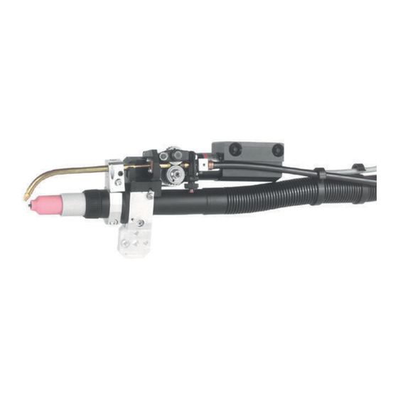
Allgemeines Produktkonzept Das WIG-Roboter-Schlauchpaket „Robacta KD Drive" eignet sich für Stahl-, CrNi- und CuSi-Anwendungen. Der integrierte Drahtantrieb dient zur Un- terstützung des verwendeten Kaltdraht-Vorschubes KD 7000 und sorgt für eine gleichmäßige Drahtförderung bei langen Schlauchpaketen. Eine präzise Drahtförderung ist Garant für ein optimales Schweißergebnis. -
Page 5: Erstausrüstung - Basic Kit
Erstausrüstung - Je nach Drahtdurchmesser ist für den Betrieb des WIG-Roboter-Schlauchpake- Basic Kit tes „Robacta KD Drive“ eine Erstausrüstung erforderlich. Die Erstausrüsung gibt es für folgende Schweißdraht-Durchmesser: Drahtdurchmesser Drahtdurchmesser Artikelnummer (mm) (inch) Erstausrüstung 0,8 mm .032 in. 44,0350,2139 0,9 mm .036 in. -
Page 6: Sicherheit
Sicherheit Sicherheit WARNUNG! Gefahr durch Fehlbedienung und fehlerhaft durchgeführte Arbeiten. Schwere Personen- und Sachschäden können die Folge sein. ▶ Alle in diesem Dokument beschriebenen Arbeiten und Funktionen dürfen nur von technisch geschultem Fachpersonal ausgeführt werden. ▶ Dieses Dokument vollständig lesen und verstehen. ▶... - Page 7 WARNUNG! Gefahr durch heiße Systemkomponenten und / oder Betriebsmittel. Schwere Verbrennungen und Verbrühungen können die Folge sein. ▶ Vor Beginn der Arbeiten alle heißen Systemkomponenten und / oder Be- triebsmittel auf +25 °C / +77 °F abkühlen lassen (beispielsweise Kühlmittel, wassergekühlte Systemkomponenten, Antriebsmotor des Drahtvorschu- bes, ...).
-
Page 8: Optionen
Optionen Zündhilfe Zündhilfe Zündhilfe (48,0009,0014) zur Erdung des Brennerkopfes Zuführungsrohre Zuführungsrohr 70° / 170 mm (6,69 in.) (42,0001,5494) Zuführungsrohr 70° / 135 mm (5,31 in.) (42,0001,5311) Zuführungsrohr 30° (42,0001,5611) Justierschellen Verlängerung Halteschellen-Aufnahme Halteschellen-Aufnahme Halteschellen-Aufnahme (42,0201,1525) für Binzel-CAT, für Motomann für Dinse DIX SASS (42,0201,1526) (42,0201,1524) -
Page 9: Robacta Kd Drive Montieren
Robacta KD Drive montieren Kaltdraht- Zuführung mon- Halterung tieren Hülse vom Brenner-Schlauchpaket abnehmen Schraube an der Halterung lockern Distanzscheibe Kaltdraht-Zuführung Hülse vom Brenner-Schlauchpaket in Kaltdraht- Schraube an der Halterung lockern Halterung Zuführung einsetzen, Kaltdraht-Zuführung mit mit Antriebseinheit auf Brenner-Schlauchpaket Distanzscheibe auf das Brenner-Schlauchpaket... -
Page 10: Erstausrüstung Montieren
Brennerkopf aufschrauben Erstausrüstung Für die Montage der Erstaurüstung sind neben den mitgelieferten Werkzeugen montieren folgende Werkzeuge erforderlich: Spitzzange Seitenschneider Ein-/Auslaufdüse Zuführungsrohr Drahtführungseinsatz Antriebsrad, Förderrolle Motorseitiges Antriebsrad und Förderrolle ent- Motorseitiges Antriebsrad und Förderrolle wie- fernen, Ein-/Auslaufdüse einschrauben und mit- der montieren, Drahtführungseinsatz bis zum tels Spitzzange befestigen (2x) Anschlag in das Zuführungsrohr einschieben Draht-Auslaufdüse... -
Page 11: Wig-Roboter-Schlauchpaket „Robacta Kd Drive" Anschließen
WIG-Roboter-Schlauchpaket „Robacta KD Drive“ anschließen Robacta KD Dri- ve anschließen - Z-Anschluss KD 7000 Robacta KD Drive Schlauchpaket mit Z-Anschluss MagicWave 2600 / 2600 CEL / 3000 TransTig 2600 / 2600 CEL / 3000... -
Page 12: Robacta Kd Drive Anschließen - F++-Anschluss
TransTig 2200 FK 2200 Adapterlösun- Durch die Auswahl von geeigneten Adaptern kann das WIG-Roboter-Schlauch- paket „Robacta KD Drive“ mit Z-Anschluss auch an Active-Wave-Stromquellen bzw. mit F++-Anschluss auch an anderen Fronius-WIG-Stromquellen betrieben werden: Robacta KD Drive mit Z-Anschluss Robacta KD Drive mit F++-Anschluss Adapter TT/MW (G/F) wassergekühlt... -
Page 13: Haltewinkel Montieren
Haltewinkel montieren Haltewinkel montieren (Stan- Bohrer / dard) Drill / Foret / Punta del trapano / Broca / Broca Ø5,8 Reibahle / Reamer / Alésoir / Alesatore / Escariador / Alargador Ø6G7 WICHTIG! Zum Fixieren der eingerichteten Stellung verbohren Sie die Halter mit Ø5,8 mm und reiben mittels einer Reibahle die Bohrung für den Pass-Stift Ø6G7 auf. -
Page 14: Haltewinkel Montieren (Individuell)
Haltewinkel montieren (Individuell) Haltewinkel montieren (Indi- Bohrer / viduell) Drill / Foret / Punta del trapano / Broca / Broca Ø5,8 Reibahle / Reamer / Alésoir / Alesatore / Escariador / Alargador Ø6G7 WICHTIG! Zum Fixieren der eingerichteten Stellung verbohren Sie die Halter mit Ø5,8 mm und reiben mittels einer Reibahle die Bohrung für den Pass-Stift Ø6G7 auf. -
Page 15: Bedienung
Bedienung Tasten Drahtvor- lauf / Drahtrück- lauf Taste Drahtvorlauf Dient zum stromlosen Einfädeln des Schweißdrahtes. Solange die Taste Drahtvorlauf Taste Drahtvorlauf Dient zum stromlosen Rücktransport des Schweißdrahtes. Solange die Taste Drahtrücklauf (2) gedrückt bleibt, wird der Schweißdraht zurück gefördert. -
Page 16: Schweißdraht In Robacta Kd Drive Einlaufen Lassen
Schweißdraht in Robacta KD Drive einlaufen las- Schweißdraht in Netzschalter am Kaltdraht-Vorschub in Stellung „0“ schalten, Netzkabel vom Robacta KD Dri- Netz trennen ve einlaufen las- Linkes Seitenteil des Kaltdraht-Vorschubes öffnen (14) (15) (12) (13) (11) Vorschubrollen in KD 7000 einsetzen, Schweißdraht einlaufen lassen... - Page 17 Am Kaltdraht-Vorschub langsame Einfädel-Geschwindigkeit einstellen (max. 4 m/min) Überprüfen, dass der Schwenkhe- bel (16) am Robacta KD Drive ge- schlossen ist (16) Schwenkhebel geschlossen Draht-Auslaufdüse (17) vom Zuführungsrohr abschrauben (17) Draht-Auslaufdüse vom Zuführungsrohr ab- schrauben Netzkabel des Kaltdraht-Vorschubes am Netz anschließen, Netzschalter in Stellung „I“...
- Page 18 Taste Drahtvorlauf (1) am Robacta KD Drive drücken, bis der Schweißdraht aus dem Brenner ragt bei Drahtstau an der Antriebsrolle vom Robacta KD- Drive: bei Drahtstau an der Antriebsrolle vom Robacta KD-Drive: Einfädelvorgang sofort stoppen (Taste Drahtvorlauf (1) loslassen) Spannhebel (16) öffnen WARNUNG! Gefahr durch rotierende Vorschubrollen.
-
Page 19: Schweißdraht Positionieren
Schweißdraht positionieren Schweißdraht WICHTIG! Der Schweißdraht ist mittig unter der Spitze der Wolfram-Elektrode positionieren zu positionieren, Abstand ca. 1 mm (0,04 in.). SW 2 mm (0,08 in.) SW 4 mm (0,16 in.) Schweißdraht vertikal positionieren Schweißdraht horizontal positionieren SW 5 mm (0,20 in.) 1 mm (0,04 in.) -
Page 20: Umrüsten Für Anderen Draht-Durchmesser
Umrüsten für anderen Draht-Durchmesser Ein-/ Auslaufdüsen (17) (19) (18) sowie motorsei- tige Förderrolle tauschen (20) (16) (20) Schwenkhebel (16) aufschwenken Selbstsichernde Mutter (17) mittels Gabelschlüssel SW 10 mm (0,39 in.) lösen (mittels Triebradschlüssel am motorseitigen Antriebsrad (18) gegenhal- ten) Bestehende Förderrolle (19) abnehmen Motorseitiges Antriebsrad (18) abnehmen Vorhandene Ein-/Auslaufdüsen (19) mittels Spitzzange abschrauben Neue Ein-/Auslaufdüsen (20) einschrauben und mit Spitzzange festziehen... -
Page 21: Schwenkhebelseitige Förderrolle Tauschen
Schwenkhebel- Schwenkhebel (16) aufschwenken seitige Förder- Schraubbare Achse (21) entfernen rolle tauschen Schwenkhebelseitiges Antriebsrad (22) mit vorhandener Förderrolle (19) entfernen Neue Förderrolle (19 ) auf schwenkhebelseitiges Antriebsrad (22) setzen Neue Förderrolle und schwenkhe- belseitiges Antriebsrad (19)+(22) in Schwenkhebel (16) einsetzen Neue Förderrolle und schwenkhe- belseitiges Antriebsrad (19)+(22) mittels schraubbarer Achse (21) fi-... -
Page 22: Einstellschraube Justieren
Einstellschraube justieren Allgemeines Zum exakten Ablesen bzw. Einstellen des Anpressdruckes an den Vorschubrol- len, verfügt die Einstellschraube (24) über eine Druckanzeige. Die Druckanzeige erfolgt mittels Teilungen, über einen breiten hellen Ring und einen schmalen ro- ten Ring. Je mehr Teilungen an der Einstellschraube sichtbar sind, desto größer ist der eingestellte Anpressdruck. -
Page 23: Drahtführungsseele Montieren / Austauschen
Drahtführungsseele montieren / austauschen Draht-Führungs- Für das Austauschen/Montieren der Draht-Führungsseele sind neben den mitge- seele ausbauen lieferten Werkzeugen folgende Werkzeuge erforderlich: Spitzzange Seitenschneider Spannstück Drahtführungs-Seele Spannmutter Zentralanschluss-seitig Spannmutter lösen Zentralanschluss-seitig Spannstück lösen, be- stehende Draht-Führungsseele herausziehen HINWEIS! Gefahr des Knickens der Draht-Führungsseele. Vor dem Einschieben, das Schlauchpaket gerade auslegen. -
Page 24: Variante 1: Drahtführungs-Seele Mit Zweiter Ein-/Auslaufdüse (Standard)
Variante 1: Folgende Arbeitsschritte gelten nur für Draht-Führungsseelen mit zentralan- Drahtführungs- schluss-seitiger Ein-/Auslaufdüse. Seele mit zwei- ter Ein-/ HINWEIS! Auslaufdüse (Standard) Gefahr der Beschädigung des Gewindes. Spannstück und Spannmutter vor der Montage reinigen. Drahtführungs-Seele Spannmutter Ein-/Auslaufdüse Spannstück Zentralanschluss-seitig Spannstück festschrau- Zentralanschluss-seitig Spannmutter fest- ben, Drahtführungs-Seele bündig mit dem schrauben. - Page 25 Fitting the mounting bracket (individually) Fitting the mounting bracket (individually) Operation Wire advance / wire reverse buttons Feeding the welding wire into the Robacta KD Drive Feeding the welding wire into the Robacta KD Drive Positioning the welding wire Positioning the welding wire...
-
Page 26: General
General Product concept The TIG Robacta KD Drive robot hosepack is suitable for steel, CrNi and CuSi applications. The integrated wire drive is designed to support the KD 7000 cold- wire feed in use and ensures an even wirefeed with long hosepacks. -
Page 27: Original Equipment - Basic Kit
Original equip- Depending on the wire diameter, original kit is essential for the operation of the ment - Basic kit TIG Robacta KD Drive robot hosepack. There is original equipment for the fol- lowing welding wire diameters: Wire diameter Wire diameter... -
Page 28: Safety
Safety Safety WARNING! Danger from incorrect operation and work that is not carried out properly. This can result in serious personal injury and damage to property. ▶ All the work and functions described in this document must only be carried out by technically trained and qualified personnel. - Page 29 WARNING! Danger due to hot system components and/or equipment. Can result in serious burns or scalding. ▶ Before starting work, allow all hot system components and/or equipment to cool to +25°C/+77°F (e.g., coolant, water-cooled system components, wire- feeder drive motor, etc.) ▶...
-
Page 30: Options
Options Ignition aid Ignition aid Ignition aid (48,0009,0014) to earth the torch head Feed pipes Feed pipe 70° / 170 mm (6,69 in.) (42,0001,5494) Feed pipe 70° / 135 mm (5,31 in.) (42,0001,5311) Feed pipe 30° (42,0001,5611) Adjusting clamps Extension clamp-retainer Clamp retainer Clamp retainer (42,0201,1525) -
Page 31: Fitting The Robacta Kd Drive
Fitting the Robacta KD Drive Fitting the cold- wire feed Support Remove sleeve from torch hosepack Loosen screw on the support Spacer Cold-wire feed Insert sleeve from torch hosepack in cold-wire Push support with drive unit on to torch ho-... -
Page 32: Fitting Original Equipment
Screw on the torch head Fitting original To fit the original equipment, as well as the tools supplied, the following tools are equipment required: long-nose pliers side shears Inlet/outlet nozzle Zuführungsrohr Drahtführungseinsatz Antriebsrad, Förderrolle Remove motor-side drive wheel and feed roller, Refit the motor-side drive wheel and feed roller, screw on inlet/outlet nozzle and secure with the push on wire guidance unit as far as it will go in-... -
Page 33: Attaching The Tig Robacta Kd Drive Robot Hosepack
Attaching the TIG Robacta KD Drive robot ho- sepack Connecting the Robacta KD Dri- ve - Z-connector KD 7000 Robacta KD Drive Schlauchpaket mit Z-Anschluss MagicWave 2600 / 2600 CEL / 3000 TransTig 2600 / 2600 CEL / 3000... -
Page 34: Connecting The Robacta Kd Drive - F++-Connector
TransTig 2200 FK 2200 Adapter soluti- By selecting the correct adapter, the TIG Robacta KD Drive robot hosepack with a Z connector can also operated on Active-Wave power sources or with F++-con- nector also on other Fronius-TIG-power sources: Robacta KD Drive with Z-connector... -
Page 35: Fitting The Mounting Bracket
Fitting the mounting bracket Fitting the mounting bra- Bohrer / cket (standard) Drill / Foret / Punta del trapano / Broca / Broca Ø5,8 Reibahle / Reamer / Alésoir / Alesatore / Escariador / Alargador Ø6G7 IMPORTANT! Drill a Ø5.8 mm hole for the mounting bracket and use a reamer to enlarge the hole so it can accommodate the dowel pin (Ø6G7). -
Page 36: Fitting The Mounting Bracket (Individually)
Fitting the mounting bracket (individually) Fitting the mounting bra- Bohrer / cket (individual- Drill / Foret / Punta del trapano / Broca / Broca Ø5,8 Reibahle / Reamer / Alésoir / Alesatore / Escariador / Alargador Ø6G7 IMPORTANT! Drill a Ø5.8 mm hole for the mounting bracket and use a reamer to enlarge the hole so it can accommodate the dowel pin (Ø6G7). -
Page 37: Operation
Operation Wire advance / wire reverse but- tons Wire advance button for the current-free threading of the welding wire. As long as the wire ad- vance button (1) remains pressed, the welding wire will thread in. Wire reverse button for the current-free reverse travel of the welding wire. As long as the wire reverse button remains pressed, the welding wire will be reversed. -
Page 38: Feeding The Welding Wire Into The Robacta Kd Drive
On the 4-roller drive of the cold-wire feed set the contact pressure to low using the tensioning nut (14) (max. 2) Line up the TIG Robacta KD Drive robot hosepack as straight as possible On the cold-wire feed set the threading speed to slow (max. 4 m/min) - Page 39 This can result in serious injury. ▶ Keep face and body well away from torch Press wire advance button (1) on the Robacta KD Drive, until the welding wire emerges from the torch. If the wire jams in the Robacta KD-Drive roller:...
- Page 40 Screw the wire outlet nozzle (17) on to the feed pipe (17) Screw the wire outlet nozzle on to the feed pipe On the 4-roller drive of the cold-wire feed, swivel the tensioning device (4) to a vertical position On the 4-roller drive of the cold-wire feed, set the contact pressure with the tensioning nuts (14) and (15).
-
Page 41: Positioning The Welding Wire
Positioning the welding wire Positioning the IMPORTANT! The welding wire must be positioned centrally beneath the tip of welding wire the tungsten electrode at a distance of about 1mm (0.04 in.). SW 2 mm (0,08 in.) SW 4 mm (0,16 in.) Positioning the welding wire vertically Positioning the welding wire horizontally SW 5 mm... -
Page 42: Retooling For Other Wire Diameters
Retooling for other wire diameters Changing inlet/ outlet nozzles (17) (19) (18) and motor-side feed rollers (20) (16) (20) Push up swivel lever (16) Release self-locking nut (17) using the 10 mm open-end spanner (0,39 in.) (keep steady by using the pinion spanner applied to the motor-side drive wheel (18)) Remove existing feed roller (19) Remove motor-side drive wheel (18) -
Page 43: Changing Feed Roller On Swivel-Lever Side
Changing feed Push up swivel lever (16) roller on swivel- Remove screw-on axle (21) lever side Remove drive wheel on swivel-lever side (22) with existing feed roller (19) Place new feed roller (19 ) on drive wheel (swivel lever side) (22) Insert new feed roller and swivel- lever side drive wheel (19)+(22) in the swivel lever (16) -
Page 44: Setting The Adjustment Screw
Setting the adjustment screw General For a precise reading or for making an adjustment to the contact pressure on the feed rollers, the adjusting screw (24) acts as a pressure display. The pressure is displayed by means of divisions - a wide, bright ring and a narrow red ring. The more divisions are visible on the adjusting screw, the greater the contact pressu- Setting the ad- IMPORTANT! It is only possible to set the adjustment screw when the welding... -
Page 45: Fitting / Replacing Inner Liner
Fitting / replacing inner liner Dismantling the To replace/fit the inner liner, as well as the supplied tools, the following tools are inner liner required: Long-nose pliers Side shears Tensioner Inner liner Release the nut on the central connector side Release the tensioner on the central connector side, and remove existing inner liner NOTE! -
Page 46: Variant 1: Inner Liner With Second Inlet/Outlet Nozzle (Standard)
Variant 1: Inner The following steps apply only to inner liners with inlet/outlet nozzles on the cen- liner with second tral connector side. inlet/outlet nozzle (stan- NOTE! dard) Danger of damage to thread. Clean tensioner and nut before assembly. Inner liner Inlet/outlet nozzle Tensioner Screw on central connector-side clamp tightly,... - Page 47 Montage du dispositif d’alimentation en fil froid Montage de la torche Montage de l’équipement de base Branchement du faisceau robot TIG « Robacta KD Drive » Branchement du « Robacta KD Drive » – Raccordement Z Branchement du Robacta KD Drive – Raccordement F++ Adaptateurs Monter l’angle d’arrêt...
-
Page 48: Généralités
Généralités Concept du pro- Les champs d’application du faisceau de robot TIG « Robacta KD Drive » sont les duit suivants : acier, CrNi et CuSi. Le dispositif d’entraînement de fil intégré sert à se- conder le dévidoir de fil froid KD 7000 et permet d’assurer une avance de fil régulière pour les faisceaux de grande longueur. -
Page 49: Équipement De Base - " Basic Kit
Équipement de Le faisceau de robot TIG « Robacta KD Drive » requiert un équipement de base base – « Basic qui est fonction de la section du fil utilisé. L’équipement de base est disponible kit » pour les sections de fil de soudage suivantes :... -
Page 50: Sécurité
Sécurité Sécurité AVERTISSEMENT! Danger dû à une erreur de manipulation et d'erreur en cours d'opération. Cela peut entraîner des dommages corporels et matériels graves. ▶ Toutes les fonctions et tous les travaux décrits dans le présent document doivent uniquement être exécutés par du personnel techniquement qualifié. ▶... - Page 51 AVERTISSEMENT! Danger en cas de contact avec les composants périphériques et/ou l'équipe- ment. Cela peut entraîner de graves brûlures. ▶ Avant d'entamer les travaux, laisser refroidir tous les composants périphéri- ques et/ou l'équipement chauds à +25 °C / +77 °F (par ex. réfrigérant, com- posants périphériques refroidis à...
-
Page 52: Options
Options Dispositif d’aide à l’amorçage Dispositif d’aide à l’amorçage Dispositif d’aide à l’amorçage (48,0009,0014) pour la mise à la terre de la tête de torche Tubes d’alimen- tation Tube d’alimentation 70° / 170 mm (6,69 in.) (42,0001,5494) Tube d’alimentation 70° / 135 mm (5,31 in.) (42,0001,5311) Tube d’alimentation 30°... -
Page 53: Montage Du Robacta Kd Drive
Montage du Robacta KD Drive Montage du dis- positif d’alimen- Dispositif tation en fil froid de fixation Retirer le manchon du faisceau de torche Desserrer la vis du dispositif de fixation Rondelle d’écartement Dispositif d’alimentation en fil froid Insérer le manchon du faisceau de torche dans Faire glisser l’unité... -
Page 54: Montage De L'équipement De Base
Visser la tête de torche Montage de Outre les outils fournis, vous aurez besoin pour le montage de l’équipement de l’équipement de base des outils suivants : base une pince pointue, une pince coupante diagonale. Buse d’entrée/sortie de fil Tube d’alimentation Insert de guidage du fil Roue d’entraînement, galet Retirer la roue d’entraînement côté... -
Page 55: Branchement Du Faisceau Robot Tig " Robacta Kd Drive
Branchement du faisceau robot TIG « Robacta KD Drive » Branchement du « Robacta KD Drive » – Rac- cordement Z KD 7000 Robacta KD Drive Faisceau avec avec raccordement Z MagicWave 2600 / 2600 CEL / 3000 TransTig 2600 / 2600 CEL / 3000... -
Page 56: Branchement Du Robacta Kd Drive - Raccordement F
Le choix d’adaptateurs appropriés permet de faire également fonctionner le fais- ceau de robot TIG « Robacta KD Drive » à partir d’une source de courant « Acti- veWave » lorsqu’il est équipé d’un raccordement Z ou bien à partir d’une source de courant Fronius TIG lorsqu’il est équipé... -
Page 57: Monter L'angle D'arrêt
Monter l’angle d’arrêt Monter l’angle d’arrêt (stan- Bohrer / dard) Drill / Foret / Punta del trapano / Broca / Broca Ø5,8 Reibahle / Reamer / Alésoir / Alesatore / Escariador / Alargador Ø6G7 IMPORTANT! Pour assurer la fixation dans la position définie, percer le support au diamètre 5,8 mm et, à... -
Page 58: Monter L'angle D'arrêt (Individuel)
Monter l’angle d’arrêt (individuel) Monter l’angle d’arrêt (individu- Bohrer / Drill / Foret / Punta del trapano / Broca / Broca Ø5,8 Reibahle / Reamer / Alésoir / Alesatore / Escariador / Alargador Ø6G7 IMPORTANT! Pour assurer la fixation dans la position définie, percer le support au diamètre 5,8 mm et, à... -
Page 59: Utilisation
Utilisation Touches Avance de fil / Retour de Touche Avance de fil Sert à enfiler le fil de soudage sans courant. L’enfilement du fil de souda- ge se poursuit tant que l’opérateur appuie sur la touche Avance de fil (1). Touche Retour de fil Sert à... -
Page 60: Introduction Du Fil De Soudage Dans Le Robacta Kd Drive
Toujours au niveau du dispositif d’entraînement à 4 galets du dévidoir de fil froid, introduire le fil de soudage (11) d’environ 50 mm (1,97 in) dans le guide d’amenée du faisceau de robot TIG « Robacta KD Drive » (13), en passant par le guide d’amenée (12). - Page 61 Dispositif d’entraînement à 4 galets du dévidoir de fil froid : exercer une légère pression de serrage (max. 2) au moyen de l’écrou tendeur (14). Disposer le faisceau de robot TIG « Robacta KD Drive » de façon à ce qu’il soit dans la mesure du possible aligné de manière rectiligne.
- Page 62 Appuyer sur la touche Avance de fil (1) du Robacta KD Drive jusqu’à ce que le fil de soudage sorte de la torche. En cas d’engorgement du fil de soudage au niveau du galet d’entraînement du Robacta KD Drive, procéder comme suit : arrêter immédiatement la procédure d’enfilement —...
-
Page 63: Positionnement Du Fil De Soudage
Positionnement du fil de soudage Positionnement IMPORTANT! Positionner le fil de soudage de façon à ce qu’il soit centré par rap- du fil de soudage port à la pointe de l’électrode de tungstène ; écartement : environ 1 mm (0,04 in). SW 2 mm (0,08 in.) SW 4 mm... -
Page 64: Adaptation Pour D'autres Sections De Fil
Adaptation pour d’autres sections de fil Changement des buses d’entrée/ (17) (19) (18) sortie de fil ainsi que du galet côté moteur (20) (16) (20) Relever le linguet (16). Desserrer l’écrou à serrage interne (17) au moyen de la clé plate 10 mm (0,39 in) ;... -
Page 65: Changement Du Galet Côté Linguet
Changement du Relever le linguet (16). galet côté lin- Retirer l’axe fileté (21). guet Retirer la roue d’entraînement (22) côté linguet ainsi que le galet (19). Monter le nouveau galet (19 ) sur la roue d’entraînement (22) côté lin- guet. Monter le nouveau galet et la roue d’entraînement côté... -
Page 66: Ajustage De La Vis De Réglage
Ajustage de la vis de réglage Généralités Pour lire ou régler la pression de serrage à partir des galets d’entraînement, la vis de réglage (24) dispose d’un système d’indication de pression. La pression est in- diquée par des divisions : un anneau large de couleur claire et un anneau mince de couleur rouge. -
Page 67: Montage Et Changement De La Gaine Guide-Fil
Montage et changement de la gaine guide-fil Démontage de la Outre les outils fournis, vous aurez besoin pour le changement et le montage de gaine guide-fil la gaine guide-fil des outils suivants : une pince pointue, une pince coupante diagonale. Pièce de serrage Gaine guide-fil Écrou tendeur... -
Page 68: Variante 1 : Gaine Guide-Fil Avec Seconde Buse D'entrée/Sortie De Fil (Standard)
Variante 1 : Gai- La procédure de travail décrite ci-après ne s’applique qu’aux gaines guide-fil avec ne guide-fil avec buse d’entrée/sortie de fil côté raccordement central. seconde buse d’entrée/sortie REMARQUE! de fil (standard) Risque d’endommagement du filetage. Nettoyer la pièce de serrage et l’écrou tendeur avant de procéder au montage.
Need help?
Do you have a question about the Robacta KD Drive and is the answer not in the manual?
Questions and answers