Fronius Robacta Reamer Operating Instructions Manual
Welding torch cleaning brush head for aluminium applications
Hide thumbs
Also See for Robacta Reamer:
- Operating instructions manual (76 pages) ,
- Operating instructions manual (96 pages)
Table of Contents
Advertisement
Quick Links
/ Perfect Charging /
Perfect Welding
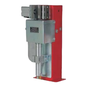
Robacta Reamer brush head for
aluminium applications
42,0426,0100,EN 016-08042019
Fronius prints on elemental chlorine free paper (ECF) sourced from certified sustainable forests (FSC).
/ Solar Energy
Operating Instructions
Spare parts list
Welding torch cleaning
Advertisement
Table of Contents
Troubleshooting

Related Manuals for Fronius Robacta Reamer


Summary of Contents for Fronius Robacta Reamer
- Page 1 / Perfect Charging / Perfect Welding / Solar Energy Operating Instructions Robacta Reamer brush head for Spare parts list aluminium applications Welding torch cleaning 42,0426,0100,EN 016-08042019 Fronius prints on elemental chlorine free paper (ECF) sourced from certified sustainable forests (FSC).
- Page 3 Thank you for the trust you have placed in our company and congratulations on buying this high-quality Fronius product. These instructions will help you familiarise yourself with the product. Reading the instructions carefully will enable you to learn about the many different features it has to offer.
-
Page 5: Table Of Contents
Contents Safety rules ..............................General ..............................Proper use ............................Environmental conditions........................Obligations of the operator........................Obligations of personnel ........................Specific hazards............................ Protecting yourself and others ......................EMC Device Classifications ........................EMC measures ............................. EMF measures............................Safety measures at the installation location and during transport ............Safety measures in normal operation .................... - Page 6 Changing the round brush ........................Changing the diagonal brushes ......................Disposal ..............................Troubleshooting Safety................................. Safety..............................Ensuring that the cleaning device is depressurised................Troubleshooting ............................Errors in program sequence ......................... Technical data Technical data............................Robacta Reamer brush head for aluminium applications ..............Appendix...
- Page 7 Spare parts list: Robacta Reamer brush head for aluminium applications ..........Circuit diagrams: Robacta Reamer brush head for aluminium applications ..........Pneumatics diagram of Robacta Reamer brush head for aluminium applications........Circuit diagrams: Wire cutter........................Declarations of Conformity.........................
-
Page 9: Safety Rules
Proper use The device is to be used exclusively for its intended purpose. The device is intended solely for the mechanical cleaning of Fronius robot welding torches in automatic mode. Any use above and beyond this purpose is deemed improper. The manufac- turer shall not be held liable for any damage arising from such usage. -
Page 10: Environmental Conditions
Environmental Operation or storage of the device outside the stipulated area will be deemed conditions as not in accordance with the intended purpose. The manufacturer shall not be held liable for any damage arising from such usage. Ambient temperature range: during operation: 0 °C to + 40 °C (32 °F to 104 °F) during transport and storage: -25 °C to +55 °C (-13 °F to 131 °F) Relative humidity:... -
Page 11: Protecting Yourself And Others
Keep your body, especially your hands, face, hair, clothing and all tools away from moving parts, such as: rotating brush head lifting device moving up/down wire cutter Protect hands, face and eyes against flying parts (shavings, etc.) and com- pressed air escaping from the cleaning nozzles. Covers may only be opened/removed for the duration of any maintenance, in- stallation or repair work. -
Page 12: Emf Measures
Supporting measures for avoidance of EMC problems: Mains supply If electromagnetic interference arises despite correct mains connec- tion, additional measures are necessary (e.g. use a suitable line fil- ter). Control lines must be kept as short as possible must run close together (to avoid EMF problems) must be kept well apart from other leads Equipotential bonding Shield, if necessary... -
Page 13: Safety Measures In Normal Operation
Safety measures Only operate the device if all safety devices are fully functional. If the safety in normal opera- devices are not fully functional, there is a risk of tion injury or death to the operator or a third party, damage to the device and other material assets belonging to the operator, inefficient operation of the device. -
Page 14: Disposal
(e.g. relevant product standards of the EN 60 974 series). Fronius International GmbH hereby declares that the device is compliant with Directive 2014/53/EU. The full text on the EU Declaration of Conformity can be found at the following address: http://www.fronius.com Devices marked with the CSA test mark satisfy the requirements of the rele- vant standards for Canada and the USA. -
Page 15: General
General... -
Page 17: General
General General The cleaning device automatically cleans MIG/MAG welding torches, which are used to weld aluminium materials. This device al- lows you to clean the inside, front and outs- ide of the gas nozzle across a wide range of torch geometries. The result is a significant increase in the service life of wearing parts. -
Page 18: Scope Of Supply
Scope of supply NOTE! The brush head is not part of the scope of supply. Robacta Reamer brush head clea- ning device for aluminium applica- tions Spatter tray retainer Spatter tray Tightening key for cleaning motor Compressed air relief valve... - Page 19 Type Art.No. Chargen No. Wels - Austria 0.13 A 24 V p max 6 bar (87PSI) Warning notices on the cleaning device WARNING! Risk of serious injury from: mechanically powered parts compressed air escaping from the cleaning nozzles flying parts (shavings, etc.) Keep device free from current and pressure during maintenance and servic- ing.
-
Page 20: Transport
Transport Vehicles The device is to be transported by the following vehicles: on pallets using a counterbalanced lift truck on pallets using a lift truck manually WARNING! Equipment that falls or topples over can cause serious or even fatal injury. ►... -
Page 21: Controls, Connections And Mechanical Components
Controls, connections and mechani- cal components... -
Page 23: Safety
Safety Safety Observe the following safety instructions for all work described in the "Control elements, connections and mechanical components" section. WARNING! Operating the equipment incorrectly can cause serious injury and damage. The functions described must only be used by trained and qualified personnel. Do not use the functions described here until you have thoroughly read and understood the following documents: ►... -
Page 24: Controls, Connections And Mechanical Components
Controls, connections and mechanical components Control elements, connections and mechanical com- ponents Side view Front view Function Harting Han6P connection socket (X1) for a 24 V DC supply CAUTION! Risk of damage to Harting Han6P connection (X1) supply due to overcurrent. Secure supply against overcurrent with a 500 mA slow-blow fuse. -
Page 25: Harting Han6P Connecting Plug Pin Assignment (X1) For Robot Control
Harting Han6P connecting plug pin assignment (X1) for robot control General CAUTION! Risk of damage to Harting Han6P connection (X1) supply due to overcurrent. Secure supply against overcurrent with a 500 mA slow-blow fuse. NOTE! To avoid malfunction, keep the cable length between the cleaning device and robot control as short as possible. -
Page 27: Installation And Commissioning
Installation and commissioning... -
Page 29: Safety
Safety Safety Observe the following safety rules for all work described in the "Installation and start-up" section. WARNING! Incorrect operation or poorly executed work can cause serious injury or damage. All activities described in these operating instructions may only be carried out by trained and qualified personnel. -
Page 30: Ensuring That The Cleaning Device Is Depressurised
Ensuring that the Attempt to briefly activate the cleaning device without any compressed air supply to check cleaning device is whether the cleaning device is depressurised. Proceed as follows: depressurised Take protective measures: The brush head, brush head lifting device, wire cutter and cleaning nozzles could start up. -
Page 31: Before Commissioning
Before commissioning Proper use The cleaning device is to be used exclusively for cleaning Fronius robot welding torches, especially the gas nozzle and its interior, in automatic mode and within the scope of the technical data. Any use above and beyond this purpose is deemed improper. The manu- facturer shall not be held liable for any damage arising from such usage. -
Page 32: Screwing The Cleaning Device To The Underlying Surface
Screwing the cleaning device to the underlying sur- face Screwing the NOTE! cleaning device and installation Different fixings may be required to set up the installation stand depending on the stand to the un- type of underlying surface (foundation). derlying surface Fixings are therefore not included in the scope of supply of the installation stand. - Page 33 NOTE! Place the cleaning device and the spatter tray retainer on a level, firm and vibration- free surface (foundation). Position the cleaning device in such a way that the distance the robot has to travel to the cleaning position is as short as possible.
-
Page 34: Adjusting And Fitting The Standard Brush Head
Adjusting and fitting the standard brush head General NOTE! The following information applies to the use of the manufacturer's contact tips, gas nozzles and brush head. If other manufacturers' products are used, trouble-free operation of the device cannot be guaranteed. The manufacturer accepts no liability for damage arising from the use of other manufacturers' contact tips, gas nozzles or brush heads. -
Page 35: Fitting The Brush Head
Fitting the brush Remove the protective covering from the cleaning device head Fit the protective covering to the cleaning device in its original position... -
Page 36: Adjusting And Fitting The Braze+ Brush Head
Adjusting and fitting the Braze+ brush head General NOTE! The following information applies to the use of the manufacturer's contact tips, gas nozzles and brush head. If other manufacturers' products are used, trouble-free operation of the device cannot be guaranteed. The manufacturer accepts no liability for damage arising from the use of other manufacturers' contact tips, gas nozzles or brush heads. -
Page 37: Fitting The Brush Head
Fitting the brush Remove the protective covering from the cleaning device head Fit the protective covering to the cleaning device in its original position... -
Page 38: Torch Cleaning Position
Torch cleaning position Cleaning posi- End of gas nozzle is approx. 45 mm tion of the weld- (1.77 in.) beneath upper edge of clea- ing torch - ning device housing, positioned cent- standard brush rally with respect to the cleaning motor head 45 mm 1.77 inch... -
Page 39: Adjusting The Position Of The Cleaning Motor (With Standard Brush Head)
Adjusting the position of the cleaning motor (with standard brush head) Adjusting the po- Remove the protective covering from the cleaning device sition of the Ensure that the lifting device (1) is in its lowest position cleaning motor Move the welding torch to the cleaning position Remove the gas nozzle from the torch body Loosen screw (2) on the lifting device Manually push the lifting device (1) into... -
Page 40: Adjusting The Position Of The Cleaning Motor (With Braze+ Brush Head)
Adjusting the position of the cleaning motor (with Braze+ brush head) Adjusting the po- Remove the protective covering from the cleaning device sition of the Ensure that the lifting device (1) is in its lowest position cleaning motor Move the welding torch to the cleaning position Loosen screw (2) on the lifting device Manually push the lifting device (1) into its highest lift position and hold in place... -
Page 41: Installation And Function Of Mechanically-Controlled Wire Cutter (Option)
Installation and function of mechanically-controlled wire cutter (option) How the mechani- If a torch neck pushes the valve lever (1) to cally-controlled the side by more than 15° with the gas wire cutter works nozzle, the wire cutter is activated and the wire electrode is cut. - Page 42 NOTE! Use the fixings supplied with the wire cutter for the assembly shown. Use a suitable adapter to connect the wire cutter compressed air hose to the cleaning device.
-
Page 43: Installation And Function Of Electrically-Controlled Wire Cutter (Option)
Installation and function of electrically-controlled wire cutter (option) How the electri- The electrically-controlled wire cutter opens and closes when there is an active signal from cally-controlled the robot control. wire cutter works Maximum wire di- Wire electrodes with a diameter of up to 1.6 mm (0.063 in.) can be cut by the wire cutter. ameter Installing the NOTE! - Page 44 NOTE! The wire cutter must be controlled electrically by the robot control.
-
Page 45: Installing The Compressed Air Supply
Installing the compressed air supply Establishing the To establish the compressed air supply: compressed air Depressurise the compressed air supply for the supply line (1) and ensure that it re- cleaning device, mains depressurised for the duration function of the of the work on the device compressed air relief valve... -
Page 46: Manually Checking The Cleaning Device Functions
Manually checking the cleaning device functions General NOTE! Before starting the automatic cleaning process, the functions of the cleaning device must be checked manually. NOTE! To ensure that the functions are checked properly, the welding torch must be in the cleaning position. -
Page 47: Starting Up The Cleaning Device
Starting up the cleaning device Prerequisites for The following requirements must be met before the cleaning device is started up: start-up If present, the cleaning device installation stand is screwed to the underlying surface The cleaning device is screwed to the underlying surface Brush head is fitted Position of the cleaning motor has been set Compressed air supply has been established... -
Page 48: Cleaning Program And Signals
Cleaning program and signals Safety CAUTION! Risk of damage. Do not start in automated mode until the cleaning device has been properly installed and started up. -
Page 49: Cleaning Program Sequence
Cleaning program sequence Start Wire cutter option Move to pos. C - approx. 25 mm (0.98 in.) next to the wire cutter - Speed: high speed Move to pos. D - Enter wire cutter - Speed: 60 cm/min (23.62 ipm) Wait 0.5 s Move to pos. - Page 50 Reset - ’Start cleaning‘ signal Wait 1,5 s Query Stop program Cleaning ‘Low‘ - Cleaning motor not lowered motor lowered ‘High‘ Move to pos. A - approx. 50 mm (1.97 in.) above Centre of brush head - Speed: high speed...
-
Page 51: Signal Inputs And Outputs
Signal inputs and Signal input: start cleaning (cleaning motor ON, lifting device UP, compressed air supply outputs to cleaning nozzles ON) Signal output: cleaning motor down... -
Page 53: Care, Maintenance And Disposal
Care, maintenance and disposal... -
Page 55: Safety
Safety Safety Observe the following safety rules for all work described in the "Care, maintenance and dis- posal" section. WARNING! Incorrect operation or poorly executed work can cause serious injury or damage. All activities described in these operating instructions may only be carried out by trained and qualified personnel. -
Page 56: Ensuring That The Cleaning Device Is Depressurised
Ensuring that the Attempt to briefly activate the cleaning device without any compressed air supply to check cleaning device is whether the cleaning device is depressurised. Proceed as follows: depressurised Take protective measures: The brush head, brush head lifting device, wire cutter and cleaning nozzles could start up. -
Page 57: Care, Maintenance And Disposal
Care, maintenance and disposal General The cleaning device generally needs no maintenance. However, to keep the cleaning de- vice in good working condition for years to come, several points on care and maintenance must be observed. Before each start- Check the cleaning brushes on the brush head and replace worn brushes Empty the cleaning device spatter tray If fitted, empty the wire cutter tray Carry out a general visual inspection of the cleaning device and wire cutter... -
Page 58: Changing The Round Brush
Changing the NOTE! round brush In the process described below for changing the round brush, a standard brush head is shown. The process is identical for aBraze+ brush head. NOTE! Before changing the brush, note the setting of the brush head (A or B) and be sure to use this setting during assembly. -
Page 59: Changing The Diagonal Brushes
Changing the di- NOTE! agonal brushes In the process described below for changing a diagonal brush, a standard brush head is shown. The process is identical for aBraze+ brush head. NOTE! Before changing the brushes, note the setting of the brush head (A or B) and be sure to use this setting during assembly. -
Page 61: Troubleshooting
Troubleshooting... -
Page 63: Safety
Safety Safety Observe the following safety rules for all work described in the "Troubleshooting" section. WARNING! Incorrect operation or poorly executed work can cause serious injury or damage. All activities described in these operating instructions may only be carried out by trained and qualified personnel. -
Page 64: Ensuring That The Cleaning Device Is Depressurised
Ensuring that the Attempt to briefly activate the cleaning device without any compressed air supply to check cleaning device is whether the cleaning device is depressurised. Proceed as follows: depressurised Take protective measures: The brush head, brush head lifting device, wire cutter and cleaning nozzles could start up. -
Page 65: Troubleshooting
Troubleshooting Errors in program Welding torch is poorly cleaned or damaged sequence Cause: Position of the cleaning motor has been set incorrectly Remedy: Adjust the position of the cleaning motor Cause: Worn cleaning brushes on cleaning head Remedy: Replace cleaning brushes on cleaning head Lifting device is not moving up or down Cause: Compressed air relief valve closed... -
Page 67: Technical Data
Technical data... -
Page 69: Technical Data
Technical data Robacta Reamer Supply voltage + 24 V DC brush head for al- Nominal output 2.4 W uminium applica- tions Nominal pressure 6 bar 86.99 psi Air consumption 420 l/min 443.81 qt./min Max. noise emission (LWA) 82 dB (A) Standard I/O Input: + 24 V DC/ max. -
Page 71: Appendix
Appendix... -
Page 72: Spare Parts List: Robacta Reamer Brush Head For Aluminium Applications
Spare parts list: Robacta Reamer brush head for al- uminium applications... - Page 73 Bürstenkopf Alu Robacta Reamer 44,0350,3058 Bürstenkopf Braze+ 44,0350,3442 44,0450,1453 Braze+ 42,0435,0221 42,0404,0409 42,0201,0261 42,0001,0040 44,0450,1452 Braze+ 42,0435,0222 42,0404,0408 Braze+ 42,0001,0261 42,0001,0039 44,0450,1451 42,0001,5601 42,0404,0332 42,0100,0522 42,0001,0041 42,0408,0109 42,0407,0080...
-
Page 74: Circuit Diagrams: Robacta Reamer Brush Head For Aluminium Applications
Circuit diagrams: Robacta Reamer brush head for al- uminium applications... -
Page 75: Circuit Diagrams: Wire Cutter
Circuit diagrams: Wire cutter Drahtelektrode abschneiden Drahtabschneider offen Drahtabschneider geschlossen Cut wire Wire cutter open Wire cutter closed... -
Page 76: Pneumatics Diagram Of Robacta Reamer Brush Head For Aluminium Applications
Pneumatics diagram of Robacta Reamer brush head for aluminium applications... -
Page 77: Declarations Of Conformity
Hereby certifies on its sole se déclare seule responsable du fait dass folgendes Produkt: responsibility that the following que le produit suivant: product: Robacta Reamer Bürstenkopf Robacta Reamer Bürstenkopf Robacta Reamer Bürstenkopf Gasdüsenreinigungsgerät Gas nozzle cleaner Appareil de nettoyage de buses gaz auf das sich diese Erklärung... - Page 80 FRONIUS INTERNATIONAL GMBH Vorchdorfer Straße 40, A-4643 Pettenbach, Austria E-Mail: sales@fronius.com www.fronius.com Under www.fronius.com/contact you will find the addresses of all Fronius Sales & Service Partners and locations...
Need help?
Do you have a question about the Robacta Reamer and is the answer not in the manual?
Questions and answers