Dresser D Series Installation, Operation And Maintenance Manual
Hide thumbs
Also See for D Series:
- Installation supplement manual (24 pages) ,
- Testing manual (12 pages)

Related Manuals for Dresser D Series


Summary of Contents for Dresser D Series
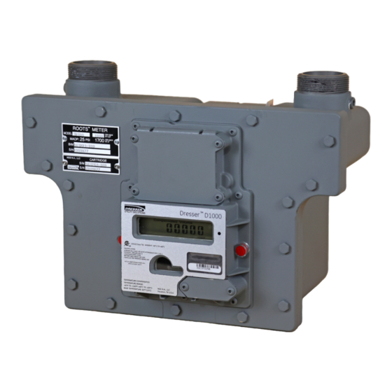
- Page 1 Dresser Measurement Dresser Series D Meter Models D630, D800 and D1000 Installation, Operation and Maintenance Manual...
- Page 2 2 | Dresser Measurement...
-
Page 3: Table Of Contents
10.4.4.1. Testing Compensated Accuracy Hazardous Locations 10.4.4.2. Testing Non-Compensated Accuracy 37 8. Meter Operation 10.5. Proving with Dresser Model 5 Transfer Prover 38 8.1. Volume Measurement 10.5.1. Establish IrDA Cable Connection 8.1.1. Imperial Or Metric Measurement Options 18 10.5.2. Model 5 Prover Software Configuration 38 8.1.2. -
Page 4: Introduction
2. Performance Characteristics actually installing the meter. This unique design allows for The Dresser Series D meter accuracy is not affected by low easy replacement of existing diaphragm meters without or varying line pressures. The meter is suitable for use at the need for re-piping, or updates to existing company in- pressures ranging from a few inches of water column (w.c.) -
Page 5: Receiving, Handling & Storage
Do not accept any shipment that has evidence natural gas and other non-corrosive gases at constant of mishandling in transit without making an or varying flow rates. The Dresser Series D meter has immediate inspection of package for dam- superior rangeability to most small commercial meters age. -
Page 6: Recommended Installation/Maintenance Tools
• SNAP IR Prover cable • 3/32” Allen Wrench • Holder - IR Prover cable • 1/8” Allen Wrench Dresser Transfer Prover Interface and IR Prover Cable • Phillips-head screw driver (Purchased separately) • Ratchet with 7/16” socket • Model 5 and Model 6 IR Prover Cable Serial IrDA Communications Kit •... - Page 7 3. Three to five seconds after the name of the value or the parameter appears, the screen will switch to show you the value of the selected parameter. D Series IOM Manual NGS.MI.0039b | 7...
-
Page 8: Data Display Screen And Icons
B. Individual icons will display depending on the function or parameter, and how you have configured the meter Pounds per square inch using the Dresser MeterWare software. Refer to Kilopascal Section 8 for more information. Refer to Table 2 for Absolute Icon descriptions. -
Page 9: Placing Meter In Line - Before Start Up
Ensure the washer is properly installed or the swivels will not seal properly against the meter ferrules (spuds). Figure 7.4 Example - Meter placed in line Figure 7.1 Example - Proper installation of washer into swivel D Series IOM Manual NGS.MI.0039b | 9... -
Page 10: Meter Start-Up
The Series D cause an over-speed condition which may meters also incorporate a leak test feature as de- damage the meter. Resulting damage is not covered scribed in Section 7.1.3.3. by warranty. 10 | Dresser Measurement... -
Page 11: Downstream Leak Test Procedure
In comparison, one revolution of the 1/4 ft test hand on a Series D meter with a mechanical index is 8. Once the meter is operating smoothly, slowly close equivalent to 33.75 revolutions of the Dresser D800 the bypass valve to the fully closed position. RPM Wheel. - Page 12 L K T PA S S Figure 7.9 Example - Leak Test Pass Screen L K T FA I L Figure 7.11 Example - “Advanced” screen of the Dresser Meter- Ware software Figure 7.10 Example - Leak Test Fail Screen 5.
-
Page 13: Amr Installation
Figure 7.19 Example to properly clamp the splice. Figure 7.16 Example - Pulse output with male mating pigtail connection installed Figure 7.19 Example - Use proper crimping pliers on Gel Cap splice D Series IOM Manual NGS.MI.0039b | 13... - Page 14 Figure 7.25 Example. Leave the screw loose for now. Figure 7.22 Example - Meter cable routed across back plate Figure 7.25 Example - Mounting plate attached to the nut 14 | Dresser Measurement...
-
Page 15: Pulse Output Connections
(supplied) can be installed on the Endpoint Module as shown at Figure 7.27 Example. Figure 7.29 Example - Volume Configuration screen in Dresser MeterWare To ensure that your pulse outputs are properly wired, the MeterWare software has a test function available on the Advanced screen, as shown in Figure 7.30 Example. -
Page 16: Pulse Output Wiring Instructions For Hazardous Locations
Figure 7.32 Example. This information is also contained in Table 1. For wiring products in hazardous locations, refer to the wiring guide in Figure 7.33 Example. Figure 7.31 Example - Send test Pulses screen in Dresser MeterWare Note: For more information on configuring and testing pulse outputs, consult the Dresser MeterWare manual. - Page 17 D Series IOM Manual NGS.MI.0039b | 17...
-
Page 18: Meter Operation
8. Meter Operation Dresser MeterWare is the computer software which connects your computer to the meter. The software pro- vides the capability to configure the meter, as well as download logged data and update the meter firmware. A serial IrDA cable connects the meter to the MeterWare software. -
Page 19: Temperature Measurement
15°C for metric applications. • High Temperature Alarm Limit: when temperature goes above the user defined limit. For ease of calibration, there is a provision in the Dresser MeterWare software to perform a single point tempera- • Low Temperature Alarm Limit: when temperature ture field calibration. -
Page 20: Meterware Notices
Figure 8.4 Example - Faults and Alarms Screen as dis- played in Dresser MeterWare Figure 8.2 Example - Live Data Screen showing Faults in Dresser Meter- Ware Software Figure 8.3 Example - Live Data Screen showing Alarms in Dresser Meter-... -
Page 21: Fault And Alarm Pulse Outputs
Data logs are recorded hourly. The meter maintains 150 days of hourly logs on a first in first out (FIFO) basis. The Data Logging feature is not configurable. The user can decide how many days of hourly logs to download using the Dresser MeterWare software. 8.5.2. Logged Parameters The meter has non-volatile memory. -
Page 22: Audit Log
9.2 Cleaning Meter and Instrument Housing Clean the meter and Instrument housings with hot water and soap or Isopropyl alcohol. Important: Aromatics, Ketones, and Chlorinated hydrocarbons will damage the plastic cover. Do not use acetone, carbon tetrachloride, etc. 22 | Dresser Measurement... -
Page 23: Temperature Probe Replacement
Figure 9.4 Example. Figure 9.3 Example - Press and release the black connector to remove temperature probe D Series IOM Manual NGS.MI.0039b | 23... -
Page 24: Instrument Replacement
Figure 9.11 Example. Afterwards, gently pull the cable all the way out of the cable gland. Figure 9.7 Example - Remove 4 screws on battery compartment Figure 9.10 Example - Remove AMR plate Figure 9.8 Example - Remove battery 24 | Dresser Measurement... -
Page 25: Instrument Installation
Figure 9.16 Example - Wiegand wires placed inside 1. To install the new instrument, place a new gasket holder on the meter – lip side up, as shown in Figure 9.13 Example. Figure 9.13 Example - Place gasket onto meter D Series IOM Manual NGS.MI.0039b | 25... - Page 26 Example. This will prevent the probe leads from be- coming trapped behind the instrument housing. Figure 9.22 Example - Gasket placed on battery cover Figure 9.19 Example - Temperature probe extended through the front of the instrument cover 26 | Dresser Measurement...
-
Page 27: Battery Maintenance
10-12 inch pounds. • Installed by qualified and competent profession- als who have undergone suitable training for instrumentation used in areas with potentially explosive atmospheres. Figure 9.25 Example - Attach AMR plate to the meter. D Series IOM Manual NGS.MI.0039b | 27... -
Page 28: Removing Meter From Service
Figure 9.29 meter set before working on the meter. Release Example. pressure at a rate less than 5 psig/second. Figure 9.29 Example - Disconnect the wiring 4. Connect the main circuit wire to a new battery pack. 28 | Dresser Measurement... -
Page 29: Cartridge Cleaning And Replacement
Soapy water, Snoop or gas analyzers ® are commonly used for this procedure. Figure 9.31 Example - Clean out plug on bottom of meter D Series IOM Manual NGS.MI.0039b | 29... -
Page 30: Measurement Cartridge Installation
A proving cable is available for testing the meter using the same IrDA (infrared) interface used for communication with the meter. The prover cable allows for rapidly testing Compensated and Non-Compensated accuracy on the Dresser Transfer Prover and the Honeywell American SNAP Proving Systems. - Page 31 3. Once back on the Configuration screen (Figure 10.3 Example), select Upload to unit. Figure 10.3 Example - Configuration screen in Dresser MeterWare 4. The chosen prove mode can then be selected on the LCD screen display of the meter.
-
Page 32: Cleanout Plug
5. When you exit the test setup screen, you should see Meter Size: the meter test file in the “OTHER” manufacturer cat- egory. After you verify the meter test is added, install the meter on the test bench. (Refer to Section 10.4.3) 32 | Dresser Measurement... -
Page 33: Testing Procedures
“Series D Meter” meter, then click “EXIT” and now you should see “Series D Meter” in the “METER” area. Figure 10.11 Example - IrDA Proving cable installed on meter D Series IOM Manual NGS.MI.0039b | 33... -
Page 34: Placing Into Compensated Prove Mode
“ACCEPT” button and the meter test will be saved. Figure 10.13 Example - Light on IrDA cable indicates connec- tion is established 4. Once the meter tests are complete you can press the “ACCEPT” button and the meter test will be saved. 34 | Dresser Measurement... -
Page 35: Configuring Snap Mmx Version
10.5 Proving with Dresser Model 5 Transfer Prover 10.5.2. Model 5 Prover Software Configuration 10.5.1 Establish IrDA Cable Connection The Model 5 Prover software must be set up as circled on the left side of the screen shot in Figure 10.18 Example. -
Page 36: Installation Of Meter On Bench
10.5.3 Explanation of Prover Configuration Screen 10.6 Proving with Dresser Model 6 Transfer Prover 10.5.3.1. Left Side of Prover Configuration Screen 11. Differential Testing • Prover Capacity: Select “10M (10,000cfh/283.2 m3)” for Only a change in the internal resistance of a meter can flow rates above 100 cfh. -
Page 37: Testing Modes
W.C. %Change Initial Tests - New Meter Periodic Check Tests Figure 11.3 Example - Having a single data chart for each meter provides detailed history of differential rate tests for future use D Series IOM Manual NGS.MI.0039b | 37... -
Page 38: Differential Test Procedure
Follow the 12. Upgrading Instrument Firmware manufacturer’s instructions for proper installation Using the Dresser MeterWare software and the IrDA and operating procedures. On the upstream side of cable assembly, which is part of the communications kit,... -
Page 39: Differential Testing Procedures
Firmware Upgrade tab refer to Figure 12.2 Example. Figure 12.2 Example- Firmware Upgrade Tab 2. From the next screen, click Select File. Refer to Figure 12.3 Example. Figure 12.3 Example - Firmware Upgrade Screen D Series IOM Manual NGS.MI.0039b | 39... - Page 40 6. In the Status box on the Firmware Upgrade screen, the message In Progress will appear. Refer to Figure 12.6 Example. Figure 12.6 Example - MeterWare software showing In Progress status 8. Once communication is fully established, the firmware upgrade begins. 40 | Dresser Measurement...
-
Page 41: Firmware Upgrade Process
3. When the firmware upgrade is complete, the three squares are green and the screen displays the message Firmware updated successfully. Refer to Figure 12.9 Example. Figure 12.9 Example - Firmware upgrade is complete. D Series IOM Manual NGS.MI.0039b | 41... -
Page 42: Specifications
• Total Ambient temperature effect: Less than 0.1°F (0.05°C) over entire temperature range • Pressure Compensation: Programmable Fixed Factor Temperature Accuracy: Table 1: Temperature Reading Accuracy Temperature Reading Accuracy -40°F to 140°F: +/- 0.9°F (-40°C to 60°C: +/- 0.5°C) 42 | Dresser Measurement... - Page 43 Two (2) minute proving with a Model 5 • Max input voltage: 8.2V (hazardous areas) or 30V Communication: (non-hazardous areas) (Optical reading port requires optical probe and Dresser Flow Selection: MeterWare software (data downloads, programming, Firmware upgrades)) • Forward, Reverse, Forward – Reverse, Reverse –...
-
Page 44: Meter Capacity
103.4 1.03 1260 1597 1996 2630 3393 35,7 45,3 56,5 74,5 96,0 137.9 1.38 1470 1868 2335 3080 3970 41,6 53,0 66,1 87,2 112,3 172.4 1.72 1690 2140 2675 3530 4547 47,9 60,7 75,7 100,0 128,7 44 | Dresser Measurement... - Page 45 4. Once all the screws are removed, pull off the front enclosure as shown in Figures 16.3 & 16.4 Examples. Figure16.6 Example- Remove 4 (#10-24) screws on main gasket Figure 16.3 Example - Pull front enclosure off D Series IOM Manual NGS.MI.0039b | 45...
- Page 46 2. Use compressed air to completely dry the meter, will cause a leak path. Also, by holding the measure- being careful not to over-speed. ment cartridge in place the load across the measure- ment cartridge end cover is more evenly distributed. 46 | Dresser Measurement...
- Page 47 Figures 16.16 & 16.17 Examples. Figure 16.12 Example - Apply grease to gasket Figure 16.16 Example - Aligning gasket slots with ribs Figure 16.13 Example- Tighten (#10-24) screws D Series IOM Manual NGS.MI.0039b | 47...
- Page 48 Refer to Figure 16.19 Example. Note: On new meters, the cartridge badge is attached to the “ROOTS Meter” badge. The badge is scored so the “CARTRIDGE” portion of the badge will break off when bent. 48 | Dresser Measurement...
- Page 49 T: 1-800-521-1114 F: 1-800-335-5224 © 2024 Natural Gas Solutions North America, LLC – All rights reserved. Dresser Utility Solutions reserves the right to make changes in specifications and features shown herein, or discontinue the product described at any time without notice or obligation.
Need help?
Do you have a question about the D Series and is the answer not in the manual?
Questions and answers