Table of Contents
Advertisement
Quick Links
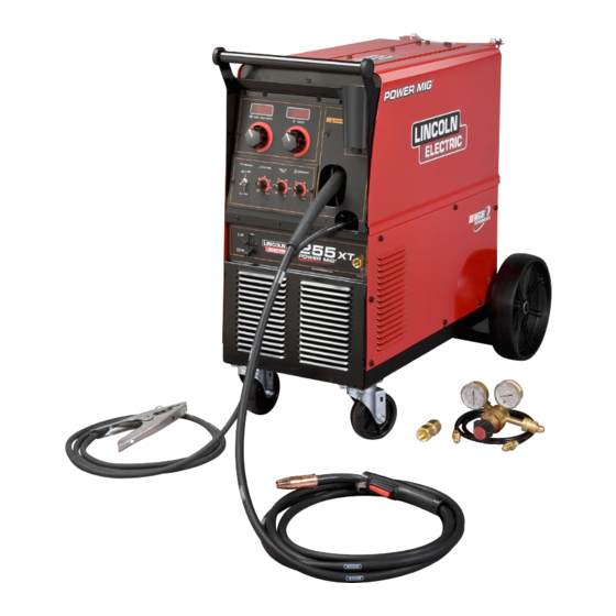
POWERMIG
255XT
®
For use with machines having Code Numbers:
11519, 11520
SERVICE MANUAL
SVM210-A
| Issue D ate 11-Apr
© Lincoln Global, Inc. All Rights Reserved.
NOTE: This manual will cover most of the troubleshooting and repair
procedures for the code numbers listed. Some variances may exist when
troubleshooting/repairing later code numbers.
Advertisement
Chapters
Table of Contents
Troubleshooting

Subscribe to Our Youtube Channel
Related Manuals for Lincoln Electric 11519


Summary of Contents for Lincoln Electric 11519
- Page 1 Some variances may exist when troubleshooting/repairing later code numbers. POWERMIG 255XT ® For use with machines having Code Numbers: 11519, 11520 SERVICE MANUAL SVM210-A | Issue D ate 11-Apr © Lincoln Global, Inc. All Rights Reserved.
- Page 2 Miami, Florida 33135 or CSA Standard W117.2-1974. A Free copy of “Arc Welding Safety” booklet E205 is available from the Lincoln Electric Company, 22801 St. Clair Avenue, Cleveland, Ohio 44117-1199. BE SURE THAT ALL INSTALLATION, OPERATION, MAINTENANCE AND REPAIR PROCEDURES ARE PERFORMED ONLY BY QUALIFIED INDIVIDUALS.
- Page 3 SAFETY ELECTRIC SHOCK can kill. ARC RAYS can burn. 3.a. The electrode and work (or ground) circuits 4.a. Use a shield with the proper filter and cover are electrically “hot” when the welder is on. plates to protect your eyes from sparks and Do not touch these “hot”...
- Page 4 SAFETY WELDING and CUTTING CYLINDER may explode SPARKS can cause fire or if damaged. explosion. 7.a. Use only compressed cylinders containing the correct shielding gas for the 6.a. Remove fire hazards from the welding area.If process used and properly operating this is not possible, cover them to prevent the welding sparks regulators designed for the gas and from starting a fire.
- Page 5 SAFETY 6. Eloigner les matériaux inflammables ou les recouvrir afin de PRÉCAUTIONS DE SÛRETÉ prévenir tout risque d’incendie dû aux étincelles. Pour votre propre protection lire et observer toutes les instructions 7. Quand on ne soude pas, poser la pince à une endroit isolé de et les précautions de sûreté...
- Page 6 (89/336/EEC). It was manufactured in conformity with a national standard that implements a harmonized standard: EN 60974-10 Electromagnetic Compatibility (EMC) Product Standard for Arc Welding Equipment. It is for use with other Lincoln Electric equipment. It is designed for industrial and professional use. Introduction All electrical equipment generates small amounts of electromagnetic emission.
- Page 7 SAFETY Electromagnetic Compatibility (EMC) The size of the surrounding area to be considered will depend on the structure of the building and other activities that are taking place. The surrounding area may extend beyond the boundaries of the premises. Methods of Reducing Emissions Mains Supply Welding equipment should be connected to the mains supply according to the manufacturer’s recommen- dations.
- Page 8 - MASTER TABLE OF CONTENTS FOR ALL SECTIONS - Page Safety ................i-vi Installation .
-
Page 9: Table Of Contents
TABLE OF CONTENTS - INSTALLATION SECTION Installation ................A-1 Technical Specifications . - Page 10 INSTALLATION ® TECHNICAL SPECIFICATIONS – POWER MIG 255XT INPUT – SINGLE PHASE ONLY Standard Input Current @ 200 Amp Input Current @ 250 Amp Voltage/Frequency Rated Output Rated Output 208/230/60 Hz *47/44 Amps *56/52 230/460/575/60 Hz 41/20/16 Amps 50/24/19 With 115V receptacle loaded to 15A. RATED OUTPUT Volts at rated Amps...
-
Page 11: Installation
INSTALLATION Read entire installation section before starting 1. Before starting the installation, check with the local installation. power company if there is any question about whether your power supply is adequate for the volt- SAFETY PRECAUTIONS age, amperes, phase, and frequency specified on the welder nameplate. -
Page 12: Output Polarity Connections
INSTALLATION 4. Using the instructions in Figure A.3, have a quali- OUTPUT POLARITY CONNECTIONS fied electrician connect the receptacle or cable to The welder, as shipped from the factory, is connected the input power lines and the system ground per the for electrode positive (+) polarity. -
Page 13: Shielding Gas
INSTALLATION SHIELDING GAS NOTE: If connecting to 100% CO 2 cylinder, insert regulator adapter between regulator and (For Gas Metal Arc Welding Processes) Customer must provide cylinder of appropriate type cylinder valve. If adapter is equipped with a plastic washer, be sure it is seated for shielding gas for the process being used. - Page 14 NOTES Power MIG® 255XT...
- Page 15 TABLE OF CONTENTS - OPERATION SECTION Operation ................B-1 Safety Precautions .
-
Page 16: Operation
OPERATION Read entire Operation section before operating GENERAL DESCRIPTION the Power MIG® 255XT. The Power MIG® 255XT is a complete semiautomatic constant voltage DC arc welding machine built to meet WARNING NEMA specifications. It combines a constant voltage power source and a constant speed wire feeder with a microcomputer-based controller to form a reliable high- ELECTRIC SHOCK can kill. -
Page 17: Welding Capability
OPERATION WELDING CAPABILITY WIRE SIZE CONVERSION PARTS The Power MIG® 255XT is rated to feed .025 through The Power MIG® 255XT is rated at 250 amps @ 26 .045" (0.6-1.2 mm) solid or cored electrode sizes. volts, at a 40% duty cycle based on a ten minute cycle time. -
Page 18: Wire Reel Loading - Readi Reels, Spools Or Coils
OPERATION To Mount 10 to 44 Lb. (4.5-20 kg) Spools (12"/300 WIRE REEL LOADING - READI mm Diameter) or 14Lb.(6 Kg) Innershield Coils: REELS, SPOOLS OR COILS To Mount a 30 Lb. (14 kg) Readi-Reel Package (For 13-14 lb. (6 Kg) Innershield coils, a K435 Coil (Using the Molded Plastic K363-P Readi-Reel Adapter must be used). -
Page 19: Idle Roll Pressure Setting
OPERATION 3. Release the pressure on the idle roll by swinging the WIRE DRIVE CONFIGURATION adjustable pressure arm down toward the back of (See Figure B.4) the machine. Lift the cast idle roll assembly and Changing the Gun Receiver Bushing allow it to sit in an upright position. - Page 20 OPERATION FIGURE B.4 - WIRE DRIVE ASSEMBLY THUMB SCREW GUN RECEIVER BUSHING OUTER WIRE GUIDE CONNECTOR BLOCK SOCKET HEAD CAP SCREW LOOSEN TIGHTEN Power MIG® 255XT...
-
Page 21: Setting Run-In Speed On Standard Power Mig® Feeder
OPERATION It is not necessary to repeat either of the above SETTING RUN-IN SPEED ON STAN- procedures each time the unit is powered up. The unit DARD Power MIG® FEEDER will remember the run-in mode from the previous power down and return you to that same state upon FAST OR SLOW RUN-IN MODE SELECTION, your next power up. -
Page 22: Making A Weld
OPERATION MAKING A WELD D. Burnback Time control provides manual adjustment burnback time (0-250 milliseconds) for any selected welding mode. this 1. Check that the electrode polarity is correct for the control should be set as low as possible without the process being used, then turn the power switch ON. -
Page 23: Avoiding Wire Feeding Problems
OPERATION FAN CONTROL WARNING The fan is designed to come on automatically when a When using an open arc process, it is necessary to weld arc is established. The fan will stay on for a use correct eye, head, and body protection. minimum of 6 minutes after the weld arc is terminated. -
Page 24: Welding Thermal Overload Protection
OPERATION B-10 B-10 WELDING THERMAL OVERLOAD PROTECTION The Power MIG® 255XT has built-in protective thermostats that respond to excessive temperature. They open the wire feed and welder output circuits if the machine exceeds the maximum safe operating temperature because of a frequent overload, or high ambient temperature plus overload. - Page 25 TABLE OF CONTENTS - ACCESSORIES SECTION Accessories ................C-1 Drive Rolls Kits .
-
Page 26: Accessories
ACCESSORIES DRIVE ROLL KITS ALTERNATIVE MAGNUM GMAW GUN AND CABLE ASSEMBLIES Refer to Table C.1 for various drive roll kits that are available for the Power MIG® 255XT. All items in Bold The following Magnum 250L gun and cable assemblies are supplied standard with the Power MIG®... -
Page 27: Spool Gun
ACCESSORIES SPOOL GUN WARNING Remove all input power to the Power MIG® 255XT before proceeding. ------------------------------------------------------------------------ The Power MIG® 255XT provides direct connection and use of the Spool Gun (with remote speed control). It also provides gun trigger switch transfer between the machine’s use with its feeder gun or the spool gun for same polarity welding with different wire and gas processes. -
Page 28: Connecting The Spool Gun
ACCESSORIES FIGURE C.1 - CONNECTING THE SPOOL GUN 7-PIN SPOOL GUN RECEPT ACLE K2445-1 CABLE ADAPTER (7-pin to 6-pin) Note: This adapter is only for The Magnum SG Spool Gun. + POSITIVE CABLE AND STUD GAS LINE AND 5/8 FITTING MAKING A WELD WITH THE 3. -
Page 29: Making A Weld With The Magnum Sg Spool Gun
ACCESSORIES MAKING A WELD WITH THE See the following procedure for setting the Wire Speed Feed using the Magnum SG Spool Gun: MAGNUM SG SPOOL GUN Wire Feed Speed SG Spool Gun Wire Feed Speed The Power MIG® 255XT control circuitry is designed to Display Approximate Range sense either the spool gun or (built in) wire feeder... -
Page 30: Magnum 250Lx Push-Pull And Push-Pull Adapter
ACCESSORIES MAGNUM 250LX PUSH-PULL GUN AND PUSH PULL ADAPTER For heavier duty aluminum applications when use of large 16 pound aluminum spools of wire are desired the following push pull gun and adapter kit are available. Magnum 250LX Push Pull Gun (K2704-1) This pistol grip push pull gun is similar to the Magnum 250LX spool gun except it is designed to feed large spools of wire. -
Page 31: Make A Weld With The Magnum 250Lx Push-Pull Gun
ACCESSORIES CONNECTING THE MAGNUM 250 MAKE A WELD WITH THE LX PUSH-PULL GUN (K2704-1) AND MAGNUM 250LX PUSH-PULL GUN MAGNUM 250LX PUSH-PULL GUN 1. Power MIG® 255XT ADAPTER (K2705-1 a. Set machine to non spool gun operation. b. Turn the Power MIG® 255XT input power ON See Figure C.2 adjusting the voltage control at the front panel. - Page 32 NOTES Power MIG® 255XT...
- Page 33 TABLE OF CONTENTS - MAINTENANCE SECTION Maintenance ................D-1 Safety Precautions .
- Page 34 MAINTENANCE b. Screw the appropriate fixed gas nozzle fully onto SAFETY PRECAUTIONS the diffuser. Either the standard .50" (12.7 mm) flush nozzle or other optional flush or recessed WARNING (spray arc) nozzle sizes may be used. (See Table D.2 in this section.) ELECTRIC SHOCK can kill.
- Page 35 MAINTENANCE Flex the cable over its entire length and again blow out Insert a new untrimmed liner into the connector the cable. Repeat this procedure until no further dirt end of the cable. Be sure the liner bushing is sten- comes out.
- Page 36 MAINTENANCE FIGURE D.1 TABLE D.2 ACCESSORIES AND EXPENDABLE REPLACE- SET SCREW MENT PARTS FOR MAGNUM 250L GUN AND BRASS CABLE CONNECTOR CABLE ASSEMBLIES 1-4" (31.8mm) English Metric LINER TRIM LENGTH Description Part No. Size Size SET SCREW CABLE LINER For 15' KP1934-2 .025 –...
- Page 37 MAINTENANCE 1. Case Front Assembly 2. Rear Panel Assembly 3. Center Assembly 4. Wire Drive Assembly 5. Base & Power Component Assembly 6. Covers Assembly FIGURE D.1 - MAJOR COMPONENT LOCATION Power MIG® 255XT...
- Page 38 NOTES Power MIG® 255XT...
- Page 39 TABLE OF CONTENTS-THEORY OF OPERATION SECTION Theory of Operation ..............E-1 Input Line Voltage and Main Transformer .
- Page 40 THEORY OF OPERATION FIGURE E.2 — INPUT LINE VOLTAGE AND MAIN TRANSFORMER SPOOL SOLENOID MOTOR WIRE DRIVE MOTOR WIRE SPEED CONTROL BOARD VOLTAGE TACH TIMER ASSEMBLY 115 VAC GUN TRIGGER RECTIFIER DIODE FEEDBACK BRIDGE 30 VAC SNUBBER LINE BOARD SWITCH POWER OUTPUT POSITIVE...
- Page 41 THEORY OF OPERATION FIGURE E.3 — OUTPUT RECTIFICATION AND FEEDBACK SPOOL SOLENOID MOTOR WIRE DRIVE MOTOR WIRE SPEED CONTROL BOARD VOLTAGE TACH TIMER ASSEMBLY 115 VAC GUN TRIGGER RECTIFIER DIODE FEEDBACK BRIDGE 30 VAC SNUBBER LINE BOARD SWITCH POWER OUTPUT POSITIVE ENHANCEMENT RECONNECT...
- Page 42 THEORY OF OPERATION FIGURE E.4 — CONSTANT VOLTAGE OUTPUT SPOOL MOTOR SOLENOID WIRE DRIVE MOTOR WIRE SPEED CONTROL BOARD VOLTAGE TACH TIMER ASSEMBLY 115 VAC GUN TRIGGER RECTIFIER DIODE FEEDBACK BRIDGE 30 VAC SNUBBER LINE BOARD SWITCH POWER OUTPUT POSITIVE ENHANCEMENT CHOKE RECONNECT...
- Page 43 THEORY OF OPERATION FIGURE E.5 — WIRE DRIVE MOTOR AND FEEDBACK SPOOL MOTOR SOLENOID WIRE DRIVE MOTOR WIRE SPEED CONTROL BOARD VOLTAGE TACH TIMER ASSEMBLY 115 VAC GUN TRIGGER RECTIFIER DIODE FEEDBACK BRIDGE 30 VAC SNUBBER LINE BOARD SWITCH POWER OUTPUT POSITIVE ENHANCEMENT...
- Page 44 THEORY OF OPERATION THERMAL AND OVERLOAD OVERCURRENT PROTECTION PROTECTION The machine will automatically reduce the output if the load on the machine exceeds 300 to 320 amperes. The POWER MIG 255XT has built-in protective ther- This protects the welding power SCR’s from excessive mostats that respond to excessive temperatures.
- Page 45 THEORY OF OPERATION FIGURE E.6 — SCR OPERATION INPUT CATHODE OUTPUT NOTE: AS THE GATE PULSE IS APPLIED ANODE LATER IN THE CYCLE THE SCR OUTPUT IS DECREASED. GATE SCR OPERATION An SCR is fired by a short burst of current into the gate. A silicon controlled rectifier (SCR) is a three terminal device used to control rather large currents to a load.
- Page 46 NOTES Power MIG® 255XT...
- Page 47 TABLE OF CONTENTS - TROUBLESHOOTING AND REPAIR Troubleshooting and Repair ............. .F-1 How to Use Troubleshooting Guide .
-
Page 48: How To Use Troubleshooting Guide
HOW TO USE TROUBLESHOOTING GUIDE WARNING Service and Repair should only be performed by Lincoln Electric Factory Trained Personnel. Unauthorized repairs performed on this equipment may result in danger to the technician and machine operator and will invalidate your factory warranty. For your safety and to avoid Electrical Shock, please observe all safety notes and precautions detailed throughout this manual. -
Page 49: Pc Board Troubleshooting Procedures
Do not touch electrically hot parts. - If you return a PC board to The Lincoln Electric Company for credit, it must be in the static-shielding bag. This will prevent further damage and allow prop- CAUTION er failure analysis. - Page 50 CAUTION If for any reason you do not understand the test procedures or are unable to perform the tests/repairs safely, contact the Lincoln Electric Service Department for technical troubleshooting assistance before you proceed. Call 1-888-935-3877. Power MIG® 255XT...
- Page 51 Replace. CAUTION If for any reason you do not understand the test procedures or are unable to perform the tests/repairs safely, contact the Lincoln Electric Service Department for technical troubleshooting assistance before you proceed. Call 1-888-935-3877. Power MIG® 255XT...
- Page 52 - replace. CAUTION If for any reason you do not understand the test procedures or are unable to perform the tests/repairs safely, contact the Lincoln Electric Service Department for technical troubleshooting assistance before you proceed. Call 1-888-935-3877. Power MIG® 255XT...
- Page 53 OFF. CAUTION If for any reason you do not understand the test procedures or are unable to perform the tests/repairs safely, contact the Lincoln Electric Service Department for technical troubleshooting assistance before you proceed. Call 1-888-935-3877. Power MIG® 255XT...
- Page 54 Electric Authorized Field Service Facility. CAUTION If for any reason you do not understand the test procedures or are unable to perform the tests/repairs safely, contact the Lincoln Electric Service Department for technical troubleshooting assistance before you proceed. Call 1-888-935-3877. Power MIG® 255XT...
- Page 55 Replace. CAUTION If for any reason you do not understand the test procedures or are unable to perform the tests/repairs safely, contact the Lincoln Electric Service Department for technical troubleshooting assistance before you proceed. Call 1-888-935-3877. Power MIG® 255XT...
- Page 56 Replace. CAUTION If for any reason you do not understand the test procedures or are unable to perform the tests/repairs safely, contact the Lincoln Electric Service Department for technical troubleshooting assistance before you proceed. Call 1-888-935-3877. Power MIG® 255XT...
-
Page 57: Main Transformer Test
MAIN TRANSFORMER TEST WARNING Service and repair should be performed only by Lincoln Electric factory trained personnel. Unauthorized repairs performed on this equipment may result in danger to the technician or machine operator and will invalidate your factory warranty. For your safety and to avoid electrical shock, please observe all safety notes and precautions detailed throughout this manual. - Page 58 TROUBLESHOOTING AND REPAIR F-12 F-12 MAIN TRANSFORMER TEST (continued) FIGURE F.1 — G4824 CONTROL PC BOARD MAIN TRANSFORMER TEST POINTS (6J6) (5J6) (4J6) (8J5) #206 (16J5) (3J5) #208 (2J5) #209 (1J5) PROCEDURE NOTE: The location of plugs may vary depending WARNING on the machine code.
- Page 59 TROUBLESHOOTING AND REPAIR F-13 F-13 MAIN TRANSFORMER TEST (continued) 6. Connect main input power to the machine. 11. Turn the machine ON. 7. Turn the POWER MIG 255XT on/off power 12. Make the following voltage tests at plug J5. switch to ON. a.
- Page 60 TROUBLESHOOTING AND REPAIR F-14 F-14 MAIN TRANSFORMER TEST (continued) 14. Locate the following leads on plug J5 on the 17. Test for correct nameplate input voltage Control PC board. See Figure F.1. between the H1 lead at the ON/OFF POWER SWITCH to H2 or H3 (H5 if connected for 575 PLUG VAC) at the reconnect panel.
-
Page 61: Rectifier Diode Bridge Test
RECTIFIER DIODE BRIDGE TEST WARNING Service and repair should be performed only by Lincoln Electric factory trained personnel. Unauthorized repairs performed on this equipment may result in danger to the technician or machine operator and will invalidate your factory warranty. For your safety and to avoid electrical shock, please observe all safety notes and precautions detailed throughout this manual. - Page 62 TROUBLESHOOTING AND REPAIR F-16 F-16 RECTIFIER DIODE BRIDGE TEST (continued) FIGURE F.2 — G4824 RECTIFIER DIODE BRIDGE LOCATION. RECTIFIER DIODE BRIDGE (D2) PROCEDURE LEAD 1. Disconnect the main AC input power to the machine. 2. Remove the case top and side panels with a 3/8 in.
- Page 63 TROUBLESHOOTING AND REPAIR F-17 F-17 RECTIFIER DIODE BRIDGE TEST (continued) 6. Turn the Power MIG® 255XT ON/OFF POWER 9. Make the following voltage test: SWITCH to ON. a. Turn the machine OFF between each test. 7. Carefully make the following voltage tests: b.
- Page 64 NOTES F-18 F-18 Power MIG® 255XT...
-
Page 65: Static Scr Rectifier Assembly Test
STATIC SCR RECTIFIER ASSEMBLY TEST WARNING Service and repair should be performed only by Lincoln Electric factory trained personnel. Unauthorized repairs performed on this equipment may result in danger to the technician or machine operator and will invalidate your factory warranty. For your safety and to avoid electrical shock, please observe all safety notes and precautions detailed throughout this manual. - Page 66 TROUBLESHOOTING AND REPAIR F-20 F-20 STATIC SCR RECTIFIER ASSEMBLY TEST (continued) FIGURE F.3 — REMOVE PLUGS J6 AND J5 TO PERFORM STATIC RECTIFIER ASSEMBLY TEST PROCEDURE 1. Disconnect main AC input power to the machine. 2. Remove the case top and side panels with a 3/8 in.
- Page 67 TROUBLESHOOTING AND REPAIR F-21 F-21 STATIC SCR RECTIFIER ASSEMBLY TEST (continued) FIGURE F.4 FIGURE F.5 LOCATION OF LEADS X2 AND X3 SCR 1 TEST POINTS NEGATIVE CAPACITOR BANK BUSS LEADS X2 AND X3 CONNECTION 6. Disconnect leads X2 and X3 (braided copper 10.
- Page 68 NOTES F-22 F-22 Power MIG® 255XT...
-
Page 69: Active Scr Rectifier Assembly Test
ACTIVE SCR RECTIFIER ASSEMBLY TEST WARNING Service and repair should be performed only by Lincoln Electric factory trained personnel. Unauthorized repairs performed on this equipment may result in danger to the technician or machine operator and will invalidate your factory warranty. For your safety and to avoid electrical shock, please observe all safety notes and precautions detailed throughout this manual. - Page 70 TROUBLESHOOTING AND REPAIR F-24 F-24 ACTIVE SCR RECTIFIER ASSEMBLY TEST (continued) FIGURE F.6 — CONTROL BOARD MOLEX PLUG LOCATIONS FOR G4824 PC CONTROL BOARD PROCEDURE 1. Disconnect main AC input power to the machine. 2. Remove the case top and side panels with a 3/8 in.
- Page 71 TROUBLESHOOTING AND REPAIR F-25 F-25 ACTIVE SCR RECTIFIER ASSEMBLY TEST (continued) FIGURE F.8 FIGURE F.7 SCR TESTER CIRCUIT AND SCR CONNECTIONS LOCATION OF LEADS X2 AND X3 NEGATIVE CAPACITOR BANK BUSS LEADS X2 AND X3 CONNECTION 6. Disconnect leads X2 and X3 (braided copper strap) from the negative capacitor bank buss bar using a 1/2 in.
- Page 72 TROUBLESHOOTING AND REPAIR F-26 F-26 ACTIVE SCR RECTIFIER ASSEMBLY TEST (continued) 9. Connect the tester to the SCR 1 as shown in 15. Reconnect the tester leads. See Figure F.8. Figure F.8. a. Connect tester lead (A) to the cathode. a.
-
Page 73: Wire Drive Motor And Tachometer Feedback Test
WIRE DRIVE MOTOR AND TACHOMETER FEEDBACK TEST WARNING Service and repair should be performed only by Lincoln Electric factory trained personnel. Unauthorized repairs performed on this equipment may result in danger to the technician or machine operator and will invalidate your factory warranty. For your safety and to avoid electrical shock, please observe all safety notes and precautions detailed throughout this manual. - Page 74 TROUBLESHOOTING AND REPAIR F-28 F-28 WIRE DRIVE MOTOR AND TACHOMETER FEEDBACK TEST (continued) FIGURE F.9 — PLUG J1 LOCATION ON CONTROL PC BOARD (4J1) #555 (2J1) (6J1) #515B #206B (5J1) (1J1) PROCEDURE NOTE: POLARITY MUST BE OBSERVED FOR THESE TESTS. Test for Correct Wire Drive Motor Armature Voltage 1.
- Page 75 TROUBLESHOOTING AND REPAIR F-29 F-29 WIRE DRIVE MOTOR AND TACHOMETER FEEDBACK TEST (continued) 6. Make the following voltage tests: TEST FOR SUPPLY VOLTAGE TO TACHOMETER a. Turn the machine OFF between each test. 1. Disconnect the main AC input power to the b.
- Page 76 TROUBLESHOOTING AND REPAIR F-30 F-30 WIRE DRIVE MOTOR AND TACHOMETER FEEDBACK TEST (continued) TEST FOR FEEDBACK VOLTAGE TO CONTROL BOARD 1. Disconnect the main AC input power to the 6. If the 1.5 to 3.5 VDC is present, the tachometer machine. circuit is sending the correct feedback signal to the Control PC Board.
-
Page 77: Normal Open Circuit Voltage Waveform
TROUBLESHOOTING AND REPAIR F-31 F-31 NORMAL OPEN CIRCUIT VOLTAGE WAVEFORM 0 VOLTS 20.0 V 2.5 ms This is the typical auxiliary output volt- age generated from a properly operat- ing machine. Note that each vertical division represents 20 volts and that each horizontal division represents 2.5 milliseconds in time. -
Page 78: Typical Output Voltage Waveform - Machine Loaded
TROUBLESHOOTING AND REPAIR F-32 F-32 TYPICAL OUTPUT VOLTAGE WAVEFORM - MACHINE LOADED 0 VOLTS 20.0 V 5 ms This is the typical auxiliary output volt- age generated from a properly operat- ing machine. Note that each vertical division represents 20 volts and that each horizontal division represents 5 milliseconds in time. -
Page 79: Abnormal Output Voltage Waveform - Machine Loaded One Output Scr Not Functioning
TROUBLESHOOTING AND REPAIR F-33 F-33 ABNORMAL OUTPUT VOLTAGE WAVEFORM - MACHINE LOADED ONE OUTPUT SCR NOT FUNCTIONING 0 VOLTS 20.0 V 5 ms This is NOT a typical DC output volt- age waveform. One output SCR is not functioning. Note the increased ripple content. -
Page 80: Abnormal Open Circuit Voltage Output Capacitor Bank Not Functioning
TROUBLESHOOTING AND REPAIR F-34 F-34 ABNORMAL OPEN CIRCUIT VOLTAGE OUTPUT CAPACITOR BANK NOT FUNCTIONING 0 VOLTS 20.0 V 5 ms This is NOT the typical DC output volt- age waveform. The output capacitors are not functioning. Note the lack of “filtering”... -
Page 81: Typical Scr Gate Voltage Waveform
TROUBLESHOOTING AND REPAIR F-35 F-35 TYPICAL SCR GATE VOLTAGE WAVEFORM 0 VOLTS 2.00 V 5 ms This is a typical SCR gate pulse voltage waveform. The machine was in an open circuit condition (no load) and operating properly. Note that each vertical division represents 2 volts and each horizontal division represents 5 milliseconds in time. - Page 82 NOTES F-36 F-36 Power MIG® 255XT...
-
Page 83: Control Pc Board Removal And Replacement
CONTROL PC BOARD REMOVAL AND REPLACEMENT WARNING Service and repair should be performed only by Lincoln Electric factory trained personnel. Unauthorized repairs performed on this equipment may result in danger to the technician or machine operator and will invalidate your factory warranty. For your safety and to avoid electrical shock, please observe all safety notes and precautions detailed throughout this manual. - Page 84 TROUBLESHOOTING AND REPAIR F-38 F-38 CONTROL PC BOARD REMOVAL AND REPLACEMENT (continued) FIGURE F.10 — WIRING HARNESS AND MOLEX PLUG LOCATIONS PROCEDURE 1. Disconnect main input power the machine. 2. Open the side panels and remove the tool tray using a 5/16 in. nutdriver. 3.
- Page 85 TROUBLESHOOTING AND REPAIR F-39 F-39 CONTROL PC BOARD REMOVAL AND REPLACEMENT (continued) FIGURE F.11 — CONTROL BOARD MOUNTING TOOL TRAY MOUNTING PC CONTROL STANDOFF BOARD 4. Ensure a static electricity grounding strap is used before handling the control PC boards. 5.
- Page 86 NOTES F-40 F-40 Power MIG® 255XT...
-
Page 87: Wire Drive Assembly Removal And Replacement
WIRE DRIVE ASSEMBLY REMOVAL AND REPLACEMENT WARNING Service and repair should be performed only by Lincoln Electric factory trained personnel. Unauthorized repairs performed on this equipment may result in danger to the technician or machine operator and will invalidate your factory warranty. For your safety and to avoid electrical shock, please observe all safety notes and precautions detailed throughout this manual. - Page 88 TROUBLESHOOTING AND REPAIR F-42 F-42 WIRE DRIVE ASSEMBLY REMOVAL AND REPLACEMENT (continued) FIGURE F.12 — WIRE DRIVE ASSEMBLY REMOVAL 15 15 4D 4D 16 16 3F 3F 6A 6A 6B 6B 4A 4A 4B 4B 4C 4C 5C 5C 5D 5D 5B 5B 5A 5A 9C 9C...
- Page 89 TROUBLESHOOTING AND REPAIR F-43 F-43 WIRE DRIVE ASSEMBLY REMOVAL AND REPLACEMENT (continued) Disconnect main input power to the machine. 11. Swing the idle arm up and away from the wire drive assembly. Remove the wire gun and wire. 12. Use a screwdriver and remove the round head Lift the wire drive door to gain access to the screw, lock washer, and flat washer securing wire drive assembly.
- Page 90 NOTES F-44 F-44 Power MIG® 255XT...
-
Page 91: Scr Output Rectifier Removal And Replacement
SCR OUTPUT RECTIFIER REMOVAL AND REPLACEMENT WARNING Service and repair should be performed only by Lincoln Electric factory trained personnel. Unauthorized repairs performed on this equipment may result in danger to the technician or machine operator and will invalidate your factory warranty. For your safety and to avoid electrical shock, please observe all safety notes and precautions detailed throughout this manual. - Page 92 TROUBLESHOOTING AND REPAIR F-46 F-46 SCR OUTPUT RECTIFIER REMOVAL AND REPLACEMENT (continued) FIGURE F.13 FIGURE F.14 MIDDLE HEAT SINK LEAD DISCONNECTION LEFT HEAT SINK LEAD DISCONNECTION LEFT HEAVY MIDDLE HEAT SINK LEAD X1 LEAD HEAT SINK LEAD LEAD #204S #208S PROCEDURE 1.
- Page 93 TROUBLESHOOTING AND REPAIR F-47 F-47 SCR OUTPUT RECTIFIER REMOVAL AND REPLACEMENT (continued) FIGURE F.15 — RIGHT HEAT SINK LEAD DISCONNECTION SCR DIODE LEAD LEAD #320B ASSEMBLY LEAD #320 LEAD #209S LEAD 5. Remove lead #209S and transformer lead X4 NOTE: When installing the SCR rectifier assembly, from the right side heat sink using a 1/2 in.
- Page 94 NOTES F-48 F-48 Power MIG® 255XT...
-
Page 95: Capacitor Bank Removal And Replacement
CAPACITOR BANK REMOVAL AND REPLACEMENT WARNING Service and repair should be performed only by Lincoln Electric factory trained personnel. Unauthorized repairs performed on this equipment may result in danger to the technician or machine operator and will invalidate your factory warranty. For your safety and to avoid electrical shock, please observe all safety notes and precautions detailed throughout this manual. - Page 96 TROUBLESHOOTING AND REPAIR F-50 F-50 CAPACITOR BANK REMOVAL AND REPLACEMENT (continued) FIGURE F.16 — LOCATION OF CAPACITOR BANK REMOVAL AND REPLACEMENT COMPONENTS LEAD SCR DIODE #206 CAPACITOR LEAD BANK LEAD #206B SHUNT LEADS X1 AND X2 POWER ENHANCEMENT CHOKE LEAD OUTPUT CHOKE LEAD PROCEDURE...
-
Page 97: Main Transformer And Output Choke Removal And Replacement
REMOVAL AND REPLACEMENT WARNING Service and repair should be performed only by Lincoln Electric factory trained personnel. Unauthorized repairs performed on this equipment may result in danger to the technician or machine operator and will invalidate your factory warranty. For your safety and to avoid electrical shock, please observe all safety notes and precautions detailed throughout this manual. - Page 98 TROUBLESHOOTING AND REPAIR F-52 F-52 MAIN TRANSFORMER AND OUTPUT CHOKE REMOVAL AND REPLACEMENT (continued) FIGURE F.17 — MAIN TRANSFORMER REMOVAL LEAD OUTPUT CHOKE OUTPUT LEAD CHOKE POSITIVE LEAD NOTE: PLUG-IN LEADS ARE NOT SHOWN FOR CLARITY. LEAD LEADS X2 AND X3 MAIN TRANSFORMER POWER ENHANCEMENT...
- Page 99 TROUBLESHOOTING AND REPAIR F-53 F-53 MAIN TRANSFORMER AND OUTPUT CHOKE REMOVAL AND REPLACEMENT (continued) 11. Unplug and label leads X5, X6, X7, X8, and X9. These leads have connectors near the transformer which can be disconnected. 12. Disconnect the output choke lead from the positive capacitor bank buss using two 1/2 in.
- Page 100 NOTES F-54 F-54 Power MIG® 255XT...
- Page 101 FAN MOTOR ASSEMBLY REMOVAL AND REPLACEMENT WARNING Service and repair should be performed only by Lincoln Electric factory trained personnel. Unauthorized repairs performed on this equipment may result in danger to the technician or machine operator and will invalidate your factory warranty. For your safety and to avoid electrical shock, please observe all safety notes and precautions detailed throughout this manual.
- Page 102 TROUBLESHOOTING AND REPAIR F-56 F-56 FAN MOTOR ASSEMBLY REMOVAL AND REPLACEMENT (continued) FIGURE F.18 — FAN MOTOR ASSEMBLY REMOVAL BLADE LEAD #353 BLADE LEAD CLAMP #352 MOTOR PROCEDURE 1. Disconnect main input power to the machine. 6. Install the fan blade and tighten the fan blade clamp.
-
Page 103: Retest After Repair
TROUBLESHOOTING AND REPAIR F-57 F-57 RETEST AFTER REPAIR INPUT IDLE AMPS AND WATTS Input Volts/Hertz Maximum Idle Amps Maximum Idle Watts 230/60 OPEN CIRCUIT VOLTAGE 35-40 VDC WIRE SPEED RANGE 50 - 700 IPM (1.27 - 17.8 m/minute) Power MIG® 255XT... - Page 104 NOTES F-58 F-58 Power MIG® 255XT...
- Page 105 Wiring Diagram – Code 11519 (L12464-1) ........
- Page 106 ELEcTricaL DiaGramS WiriNG DiaGram - cODE 11519 (L12464-1) POWER MIG 255XT (208/230V) NOTES: GENERAL INFORMATION DISPLAY BOARD N.A. WELDING CABLE MUST BE OF PROPER CAPACITY FOR THE ELECTRICAL SYMBOLS PER E1537 CONTROL BOARD CURRENT AND DUTY CYCLE OF IMMEDIATE AND CAVITY NUMBERING SEQUENCE FUTURE APPLICATIONS.
- Page 107 ELEcTricaL DiaGramS WiriNG DiaGram - cODE 11520 (L12506-1) POWER MIG 255XT (230/460/575V) NOTES: DISPLAY GENERAL INFORMATION BOARD N.A. WELDING CABLE MUST BE OF PROPER CAPACITY FOR THE CONTROL BOARD ELECTRICAL SYMBOLS PER E1537 CURRENT AND DUTY CYCLE OF IMMEDIATE AND CAVITY NUMBERING SEQUENCE FUTURE APPLICATIONS.
- Page 108 Procedure Chart G3681. ELECTRICAL SYMBOLS PER E1537 (COMPONENT SIDE OF P.C. BOARD) CURRENT AND DUTY CYCLE OF IMMEDIATE AND CODE 11519, 11520 COLOR CODE: FUTURE APPLICATIONS. is capable of higher duty cycles at lower output currents B - BLACK N.B.
- Page 109 ELEcTricaL DiaGramS SchEmaTic - WELD cONTrOL Pc bD (G4823) (PG1) +15V +15V +15V 3.32K WIRE 16.2K 4066B 44.2K 0.1uF FEED INDUCTANCE SPEED 3.32K SELECT BURNBACK TIME 44.2K R182 0.1uF 4.75K DZ12 SPOT TIME 0.1uF 6.2V +15V W/ DEAD BAND "OFF" 3.32K 4066B +15V...
- Page 110 ELEcTricaL DiaGramS SchEmaTic - WELD cONTrOL Pc bD (G4823) (PG2) +15V SOLENOID DRIVE CIRCUITRY 541A SCR GATE DRIVE CIRCUITRY 400V 6 J6 202 TO SCR GATE OCI2 OCI2 390 J8 400V MAIN GAS SOLENOID 0.0047uF 400V 392 J8 1400V 0.5A 2.21K 0.022uF R176...
- Page 111 ELEcTricaL DiaGramS SchEmaTic - WELD cONTrOL Pc bD (G4823) (PG3) SPOOL GUN MOTOR DRIVE AND BRAKE +15V 541A SCR BRIDGE SNUBBER 33.2 +15V 400V 0.47uF 630V SPOOL 0.1uF R124 100V MOTOR IR2117 0.1uF 82uF +15V R206 200V 5.62K R202 0.47uF 39.2K 630V +15V...
- Page 112 ELEcTricaL DiaGramS SchEmaTic - DiSPLay Pc bD (L10951) BANK4 BANK3 BANK2 BANK1 BANK5 DISP3 DISP2 DISP1 DATA IN CLOCK /ENABLE DATA OUT MC14489 LATCH .0047 .0047 BANK4 BANK3 VOLTS BANK2 MOSI LED3 BANK1 BANK5 DISP7 DISP6 DISP5 .0047 DATA IN /ENABLE CLOCK DATA OUT...
- Page 113 Lincoln Electric discourages board level troubleshooting and repair since it may compromise the quality of the design and may result in danger to the Machine Operator or Technician.
Need help?
Do you have a question about the 11519 and is the answer not in the manual?
Questions and answers