Table of Contents
Advertisement
Quick Links
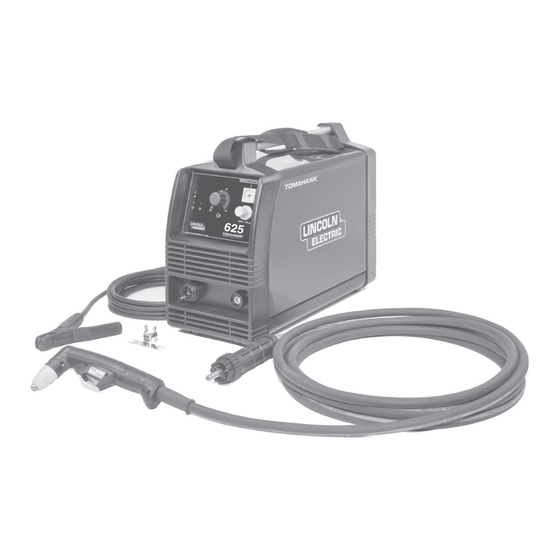
TOMAHAWK
625
®
For use with machines having Code Numbers:
11580
SERVICE MANUAL
SVM222-A
| Issue D ate 12-Jul
© Lincoln Global, Inc. All Rights Reserved.
NOTE: This manual will cover most of the troubleshooting and repair
procedures for the code numbers listed. Some variances may exist when
troubleshooting/repairing later code numbers.
Advertisement
Chapters
Table of Contents
Troubleshooting

Subscribe to Our Youtube Channel
Related Manuals for Lincoln Electric TOMAHAWK 625


Summary of Contents for Lincoln Electric TOMAHAWK 625
- Page 1 NOTE: This manual will cover most of the troubleshooting and repair procedures for the code numbers listed. Some variances may exist when troubleshooting/repairing later code numbers. TOMAHAWK ® For use with machines having Code Numbers: 11580 SERVICE MANUAL SVM222-A | Issue D ate 12-Jul ©...
- Page 2 Miami, Florida 33135 or CSA Standard W117.2-1974. A Free copy of “Arc Welding Safety” booklet E205 is available from the Lincoln Electric Company, 22801 St. Clair Avenue, Cleveland, Ohio 44117-1199. BE SURE THAT ALL INSTALLATION, OPERATION, MAINTENANCE AND REPAIR PROCEDURES ARE PERFORMED ONLY BY QUALIFIED INDIVIDUALS.
- Page 3 SAFETY ELECTRIC SHOCK can kill. ARC RAYS can burn. 3.a. The electrode and work (or ground) circuits 4.a. Use a shield with the proper filter and cover are electrically “hot” when the welder is on. plates to protect your eyes from sparks and Do not touch these “hot”...
- Page 4 SAFETY WELDING and CUTTING CYLINDER may explode SPARKS can cause fire or if damaged. explosion. 7.a. Use only compressed cylinders containing the correct shielding gas for the 6.a. Remove fire hazards from the welding area.If process used and properly operating this is not possible, cover them to prevent the welding sparks regulators designed for the gas and from starting a fire.
- Page 5 SAFETY 6. Eloigner les matériaux inflammables ou les recouvrir afin de PRÉCAUTIONS DE SÛRETÉ prévenir tout risque dʼincendie dû aux étincelles. Pour votre propre protection lire et observer toutes les instructions 7. Quand on ne soude pas, poser la pince à une endroit isolé de et les précautions de sûreté...
- Page 6 2004/108/EC. It was manufactured in conformity with a national standard that implements a harmonized standard: EN 60974-10 Electromagnetic Compatibility (EMC) Product Standard for Arc Welding Equipment. It is for use with other Lincoln Electric equipment. It is designed for industrial and professional use. Introduction All electrical equipment generates small amounts of electromagnetic emission.
- Page 7 SAFETY Electromagnetic Compatibility (EMC) The size of the surrounding area to be considered will depend on the structure of the building and other activities that are taking place. The surrounding area may extend beyond the boundaries of the premises. Methods of Reducing Emissions Mains Supply Welding equipment should be connected to the mains supply according to the manufacturer’s recommenda- tions.
- Page 8 Parts List - Tomahawk 625 ........
- Page 9 TABLE OF CONTENTS - INSTALLATION SECTION Installation ................A-1 Technical Specifications .
- Page 10 INSTALLATION TECHNICAL SPECIFICATIONS -TOMAHAWK ® INPUT - SINGLE PHASE 50 / 60 HERTZ Standard Voltage 208V, 230V ±10% / 1 / 50 / 60Hz RATED OUTPUT AT 40° C CURRENT AMPS VOLTAGE AMPS Duty Cycle 100% 24 A 89.6VDC 29 A 91.8VDC 40 A 96.0VDC...
- Page 11 INSTALLATION Read entire Installation Section before installing the HIGH FREQUENCY INTERFERENCE TOMAHAWK ® 625. PROTECTION The TOMAHAWK ® 625 employs a touch start mecha- SAFETY PRECAUTIONS nism for arc initiation which eliminates high frequency emissions from the machine as compared with spark WARNING gap and solid state type high frequency generators.
- Page 12 INSTALLATION NOTE: When using nitrogen gas from a cylinder, the The following Lincoln engine drives meet these condi- cylinder must have a pressure regulator. tions when run in the high idle mode: Ranger 250, 250LPG, 305G and 305D engine drives. •...
-
Page 13: Table Of Contents
TABLE OF CONTENTS - OPERATION SECTION Operation ................B-1 Safety Precautions . -
Page 14: Operation
OPERATION DESCRIPTION SAFETY PRECAUTIONS WARNING The TOMAHAWK ® 625 is a constant current, continu- ous control plasma cutting power source. It provides superior and reliable starting characteristics, cutting ELECTRIC SHOCK visibility and arc stability. The control system has a can kill. safety mechanism to insure that the nozzle and elec- •... -
Page 15: User Responsibility
OPERATION USER RESPONSIBILITY Because design, fabrication, erection and cutting vari- ables affect the results obtained in applying this type of information, the serviceability of a product or structure is the responsibility of the user. Variation such as plate chemistry, plate surface condition (oil, scale), plate thickness, preheat, quench, gas type, gas flow rate and equipment may produce results different than those expected. -
Page 16: Cutting Capability
OPERATION CONSUMABLE LIFE CUTTING CAPABILITY The TOMAHAWK 625 is rated at 40 amps, at 35% The expected life for the TOMAHAWK 625's electrode ® ® duty cycle on a 10 minute basis. If the duty cycle is under normal operating conditions is approximately 1000 starts/cuts. -
Page 17: Limitations
OPERATION LIMITATIONS LEDs Description Output Thermal (Red) (Yellow) Do not exceed output current and duty cycle rating of The cutting torch is energized. machine. Do not use the TOMAHAWK 625 for pipe ® Part in place error: the retaining thawing. cap is not properly Attached. -
Page 18: Cutting Process
OPERATION Turn the machine's ON/OFF POWER SWITCH to the 5. Air Pressure Gauge and Regulator Knob: Allows OFF position. regulation and monitoring of the air pressure. Items 6 thru 9 on the back of the TOMAHAWK • Connect the air supply to the machine. ®... - Page 19 OPERATION • When ready to cut, place the torch near the work, 5 - 15 Leading Angle make certain all safety precautions have been taken and pull the trigger. - The air will flow for a preflow time of 2 seconds and the pilot arc will start.
-
Page 20: Pilot Arc Discussion
OPERATION • Replace the nozzle when the orifice exit is eroded PROCEDURE RECOMMENDATIONS away or oval shaped. When properly used, plasma arc cutting is a very eco- • After the problem is found, or if there is nothing nomical process. Improper use will result in a very high apparently wrong, reset the machine by turning the operating cost. -
Page 21: Suggestions For Extra Utility From The Tomahawk
OPERATION Suggestions for Extra Utility from the • Set air pressure to recommended setting. A higher or lower pressure will cause turbulence TOMAHAWK ® 625 System: in the plasma arc, eroding the orifice of the nozzle tip. WARNING ELECTRIC SHOCK CAN KILL. •... -
Page 22: Torch Part Configuration
OPERATION B-10 B-10 TORCH PART CONFIGURATIONS There are different torch configurations depending on the cutting or gouging application. Standard Cutting Setup: In the Standard Cutting configuration the nozzle is designed not to touch the work piece. The advantage of this cutting method is good visibility of the arc. However it requires a steady hand to avoid touching the nozzle to the work piece which will cause prema- ture nozzle wear and a jagged cut. - Page 23 Refer to the torch parts decal located on your machine or the parts pages at the back of this manual for the specific part numbers required for each of these setups. ALWAYS USE GENUINE LINCOLN ELECTRIC ELECTRODES, NOZZLES, AND EXPENDABLE PARTS FOR THE BEST CUTTING PERFORMANCE. www.lincolnelectric.com TOMAHAWK ®...
- Page 24 NOTES B-12 B-12 TOMAHAWK ®...
- Page 25 TABLE OF CONTENTS - ACCESSORIES SECTION Accessories ................C-1 General Options / Accessories .
- Page 26 ACCESSORIES GENERAL OPTIONS /ACCESSORIES The following options/accessories are available for your Tomahawk Plasma cutter from your local Lincoln ® Distributor. K2377-1 - Small Canvas Cover Protect your machine when not in use. Made from attractive red canvas that is flame retardant, mildew resistant and water repellent.
- Page 27 TABLE OF CONTENTS - MAINTENANCE SECTION Maintenance ................D-1 Routine Maintenance .
- Page 28 MAINTENANCE PERIODIC MAINTENANCE WARNING WARNING ELECTRIC SHOCK CAN KILL. • Have an electrician install and ser- ELECTRIC SHOCK CAN KILL. vice this equipment. • Turn off machine at the disconnect • Turn the input power off at the fuse switch on the rear of the machine box before working on equipment.
- Page 29 MAINTENANCE FIGURE D.1 MAJOR COMPONENT LOCATIONS 1. Case Front 2. Case Back 3. Handle 4. Base 6. Wraparound 8. Control Panel 9. Nameplate 10. Inverter P.C. Board 11. Control P.C. Board 12. Air Filter 13. Pressure Switch 14. Air Inlet Pass Through 15.
- Page 30 NOTES TOMAHAWK ®...
- Page 31 TABLE OF CONTENTS-THEORY OF OPERATION SECTION Theory of Operation ..............E-1 General Description .
- Page 32 THEORY OF OPERATION FIGURE E.2 - GENERAL DISCRIPTION 045.101.079 045.101.049 GENERAL DESCRIPTION The Tomahawk 625 is an inverter based constant cur- ® rent, continuous control, plasma cutting power source. The control system has a safety mechanism to insure that the torch nozzle and electrode are correctly in place before cutting or gouging.
- Page 33 THEORY OF OPERATION FIGURE E.3 - INVERTER BOARD INVERTER BOARD This machine is designed on the “single board” con- cept in which all of the electronic devices are housed on one printed circuit board. The single phase input voltage (208-230VAC) is con- nected to the Tomahawk inverter board via an input ®...
- Page 34 THEORY OF OPERATION FIGURE E.4 - INVERTER BOARD INVERTER BOARD (continued) The 325VDC developed at the input bridge and filter The secondary winding supplies the electrode-to-noz- capacitors is applied to a half–bridge inverter circuit zle (pilot arc) and the electrode-to-work (cutting arc) that utilizes high speed switching transistors.
- Page 35 THEORY OF OPERATION FIGURE E.5 - INVERTER BOARD INVERTER BOARD (continued) There are several other functions and circuits housed on the Inverter Board. The flyback circuit utilizes the (325VDC @ 230VAC) input to generate the auxiliary power supplies (25VDC, 15VDC, and 3.3VDC) for the machineʼs internal electronic circuitry.
- Page 36 THEORY OF OPERATION FIGURE E.6 - CONTROL BOARD AND FAN MOTORS 045.101.079 045.101.049 CONTROL BOARD RED LED YELLOW LED MEANING MOTORS The cutting torch is energized. The control board is located on the front panel of the Torch parts in place Tomahawk ®...
- Page 37 THEORY OF OPERATION FIGURE E.7 - TORCH ASSEMBLY AND WORK LEAD TORCH HEAD ELECTRODE SWIRL RING NOZZLE SPACER SPACER TORCH ASSEMBLY AND WORK LEAD The torch assembly and work lead are connected to the machine via the front panel. This torch is designed to provide the best cutting performance and excellent consumable life.
- Page 38 NOTES TOMAHAWK ®...
- Page 39 TABLE OF CONTENTS - TROUBLESHOOTING AND REPAIR Troubleshooting and Repair ............. .F-1 How to Use Troubleshooting Guide .
-
Page 40: How To Use Troubleshooting Guide
HOW TO USE TROUBLESHOOTING GUIDE WARNING Service and Repair should only be performed by Lincoln Electric Factory Trained Personnel. Unauthorized repairs performed on this equipment may result in danger to the technician and machine operator and will invalidate your factory warranty. For your safety and to avoid Electrical Shock, please observe all safety notes and precautions detailed throughout this manual. -
Page 41: Pc Board Troubleshooting Procedures
Do not touch electrically hot parts. - If you return a PC board to The Lincoln Electric Company for credit, it must be in the static-shielding bag. This will prevent further damage and allow prop- CAUTION er failure analysis. - Page 42 CAUTION If for any reason you do not understand the test procedures or are unable to perform the tests/repairs safely, contact the Lincoln Electric Service Department for technical troubleshooting assistance before you proceed. Call 1-888-935-3877. TOMAHAWK ®...
- Page 43 CAUTION If for any reason you do not understand the test procedures or are unable to perform the tests/repairs safely, contact the Lincoln Electric Service Department for technical troubleshooting assistance before you proceed. Call 1-888-935-3877. TOMAHAWK ®...
- Page 44 3. Make sure the air pressure is set correctly. CAUTION If for any reason you do not understand the test procedures or are unable to perform the tests/repairs safely, contact the Lincoln Electric Service Department for technical troubleshooting assistance before you proceed. Call 1-888-935-3877. TOMAHAWK ®...
- Page 45 CAUTION If for any reason you do not understand the test procedures or are unable to perform the tests/repairs safely, contact the Lincoln Electric Service Department for technical troubleshooting assistance before you proceed. Call 1-888-935-3877. TOMAHAWK ®...
- Page 46 See Figure B.1. off smoothly. CAUTION If for any reason you do not understand the test procedures or are unable to perform the tests/repairs safely, contact the Lincoln Electric Service Department for technical troubleshooting assistance before you proceed. Call 1-888-935-3877. TOMAHAWK ®...
- Page 47 TROUBLESHOOTING AND REPAIR TOMAHAWK ®...
- Page 48 TROUBLESHOOTING AND REPAIR F-10 F-10 Observe Safety Guidelines detailed in the beginning of this manual. STATUS BOARD INDICATORS SYMPTOM CHECK Red output LED is blinking or steady with 1. Make sure there is at least 80 psi connected to the gas connec- no air flow at trigger pull.
-
Page 49: Case Wraparound Removal And Replacement Procedure
CASE WRAPAROUND REMOVAL AND REPLACEMENT PROCEDURE WARNING Service and repair should be performed only by Lincoln Electric factory trained personnel. Unauthorized repairs performed on this equipment may result in danger to the technician or machine operator and will invalidate your factory warranty. For your safety and to avoid electrical shock, please observe all safety notes and precautions detailed throughout this manual. - Page 50 TROUBLESHOOTING AND REPAIR F-12 F-12 CASE WRAPAROUND REMOVAL AND REPLACEMENT PROCEDURE (continued) FIGURE F.1 – TOP HANDLE SCREW LOCATIONS HANDLE PHILLIPS SCREW PHILLIPS SCREW PROCEDURE 5. Remove handle by gently pulling away from WARNING front panel while holding rear panel slightly to ELECTRIC SHOCK CAN KILL.
- Page 51 TROUBLESHOOTING AND REPAIR F-13 F-13 CASE WRAPAROUND REMOVAL AND REPLACEMENT PROCEDURE (continued) FIGURE F.2 – REAR PANEL SCREW LOCATIONS MOUNTING MOUNTING SCREWS SCREWS MACHINE REAR VIEW REPLACEMENT PROCEDURE 1. Reconnect ground wire from Case Wraparound to machine. 2. Replace Case Wraparound by sliding into posi- tion and pressing firmly into place against front panel.
- Page 52 NOTES F-14 F-14 TOMAHAWK ®...
-
Page 53: Capacitor Discharge Procedure
CAPACITOR DISCHARGE PROCEDURE WARNING Service and repair should be performed only by Lincoln Electric factory trained personnel. Unauthorized repairs performed on this equipment may result in danger to the technician or machine operator and will invalidate your factory warranty. For your safety and to avoid electrical shock, please observe all safety notes and precautions detailed throughout this manual. - Page 54 TROUBLESHOOTING AND REPAIR F-16 F-16 CAPACITOR DISCHARGE PROCEDURE (continued) FIGURE F.3 – INVERTER BOARD LOCATION INVERTER BOARD PROCEDURE 5. Carefully apply a resistor with insulated leads at WARNING the indicated points to discharge. Use a 25 ohm 25 Watt type resistor. See Figure F.4. ELECTRIC SHOCK CAN KILL.
- Page 55 TROUBLESHOOTING AND REPAIR F-17 F-17 CAPACITOR DISCHARGE PROCEDURE (continued) FIGURE F.4 – INVERTER BOARD TEST POINTS INPUT INPUT AUXILIARY TRANSFORMER 1000uF 1000uF 450Vdc 450Vdc MAIN TRANSFORMER OUTPUT CHOKE TOMAHAWK ®...
- Page 56 NOTES F-18 F-18 TOMAHAWK ®...
-
Page 57: Torch Lc 40 Test
TORCH LC 40 TEST WARNING Service and repair should be performed only by Lincoln Electric factory trained personnel. Unauthorized repairs performed on this equipment may result in danger to the technician or machine operator and will invalidate your factory warranty. For your safety and to avoid electrical shock, please observe all safety notes and precautions detailed throughout this manual. - Page 58 TROUBLESHOOTING AND REPAIR F-20 F-20 TORCH LC 40 TEST (continued) FIGURE F.5 – TORCH LC 40 TORCH LC 40 PROCEDURE WARNING ELECTRIC SHOCK CAN KILL. • Do not touch electrically live parts or electrode with skin or wet cloth- ing. •...
- Page 59 TROUBLESHOOTING AND REPAIR F-21 F-21 TORCH LC 40 TEST (continued) TABLE F.1 – TORCH TEST CONDITIONS AND RESULTS TEST: TORCH CONDITION: EXPECTED RESULTS: TRIGGER TRIGGER PULLED; There should be continuity “0 Ohms” between Pin 3 (Grey) to Pin 1 Remove retaining cap on torch end. (Brown) trigger wires.
- Page 60 TROUBLESHOOTING AND REPAIR F-22 F-22 TORCH LC 40 TEST (continued) FIGURE F.6 – TORCH COMPONENTS AND LEADS TRIGGER (THREADED) TORCH COUPLING SAFETY TOMAHAWK ®...
-
Page 61: Inverter Board Test
INVERTER BOARD TEST WARNING Service and repair should be performed only by Lincoln Electric factory trained personnel. Unauthorized repairs performed on this equipment may result in danger to the technician or machine operator and will invalidate your factory warranty. For your safety and to avoid electrical shock, please observe all safety notes and precautions detailed throughout this manual. - Page 62 TROUBLESHOOTING AND REPAIR F-24 F-24 INVERTER BOARD TEST (continued) FIGURE F.7 – INVERTER BOARD LOCATION INVERTER BOARD PROCEDURE 5. Give the Inverter Board a good visual check on WARNING both sides. Look for any burnt, darkened or sooty damaged areas and or components. No ELECTRIC SHOCK CAN KILL.
- Page 63 TROUBLESHOOTING AND REPAIR F-25 F-25 INVERTER BOARD TEST (continued) FIGURE F.8 – INVERTER BOARD TEST POINTS CONTROL BOARD RIBBON CABLE CONNECTOR CN15 CN2 CN16 – INPUT INPUT AUXILIARY TRANSFORMER 680uF 680uF 450Vdc 450Vdc 1.65k Ω 1.65k Ω 100k MAIN TRANSFORMER CHARGING CAPACITOR CHARGING...
- Page 64 TROUBLESHOOTING AND REPAIR F-26 F-26 INVERTER BOARD TEST (continued) FIGURE F.9 – METER PROBE CONNECTIONS (BEEP) (NO BEEP) CONDUCTION BLOCKING – – BLACK BLACK PROBE PROBE PROBE PROBE SWAP LEADS ON TEST POINTS TABLE F.2-A – INVERTER BOARD DIODE CHECKS CONDITIONS TEST POINT TEST POINT...
- Page 65 TROUBLESHOOTING AND REPAIR F-27 F-27 INVERTER BOARD TEST (continued) TABLE F.2-B – INVERTER BOARD DIODE CHECKS CONDITIONS TEST POINT TEST POINT EXPECTED COMMENTS READING MACHINE NO “BEEP” REVERSE + PROBE – PROBE DIODE CONDUCTION READING MACHINE “BEEP” FORWARD + PROBE –...
- Page 66 TROUBLESHOOTING AND REPAIR F-28 F-28 INVERTER BOARD TEST (continued) TABLE F.2-D – INVERTER BOARD DIODE CHECKS CONDITIONS TEST POINT TEST POINT EXPECTED COMMENTS READING MACHINE TP25 TP26 NO “BEEP” REVERSE + PROBE – PROBE DIODE CONDUCTION READING MACHINE TP28 TP27 “BEEP”...
-
Page 67: Air Solenoid Test
AIR SOLENOID TEST WARNING Service and repair should be performed only by Lincoln Electric factory trained personnel. Unauthorized repairs performed on this equipment may result in danger to the technician or machine operator and will invalidate your factory warranty. For your safety and to avoid electrical shock, please observe all safety notes and precautions detailed throughout this manual. - Page 68 TROUBLESHOOTING AND REPAIR F-30 F-30 AIR SOLENOID TEST (continued) FIGURE F.10 – INVERTER BOARD CONTROL BOARD RIBBON CABLE CONNECTOR CN15 CN2 CN16 – BLACK (SOLENOID) (SOLENOID) INPUT INPUT AUXILIARY TRANSFORMER 680uF 680uF 450Vdc 450Vdc 1.65k Ω 1.65k Ω 100k MAIN TRANSFORMER CHARGING CAPACITOR CHARGING...
-
Page 69: Pressure Switch Test
PRESSURE SWITCH TEST WARNING Service and repair should be performed only by Lincoln Electric factory trained personnel. Unauthorized repairs performed on this equipment may result in danger to the technician or machine operator and will invalidate your factory warranty. For your safety and to avoid electrical shock, please observe all safety notes and precautions detailed throughout this manual. - Page 70 TROUBLESHOOTING AND REPAIR F-32 F-32 PRESSURE SWITCH TEST (continued) FIGURE F.11 – PRESSURE SWITCH KNOB LOCATION PRESSURE SWITCH KNOB 1MPa = 145 psi 6 2 5 TOMAHAWK www.lincolnelectric.com PROCEDURE 5. Using the pressure regulator on the front of the WARNING Tomahawk ®...
-
Page 71: Control Potentiometer Test
CONTROL POTENTIOMETER TEST WARNING Service and repair should be performed only by Lincoln Electric factory trained personnel. Unauthorized repairs performed on this equipment may result in danger to the technician or machine operator and will invalidate your factory warranty. For your safety and to avoid electrical shock, please observe all safety notes and precautions detailed throughout this manual. - Page 72 TROUBLESHOOTING AND REPAIR F-34 F-34 CONTROL POTENTIOMETER TEST (continued) FIGURE F.12 – CONTROL BOARD TEST POINTS CONTROL BOARD FRONT PANEL MOUNTING SCREWS PROCEDURE 5. Locate the control board. See Figure F.12. WARNING 6. Using the phillips screwdriver, remove the four ELECTRIC SHOCK CAN KILL.
- Page 73 TROUBLESHOOTING AND REPAIR F-35 F-35 CONTROL POTENTIOMETER TEST (continued) FIGURE F.13 – CN9 CONTROL BOARD RIBBON CABLE CONNECTOR LOCATION CONTROL BOARD RIBBON CABLE CONNECTOR CN15 CN2 CN16 – INPUT INPUT AUXILIARY TRANSFORMER 680uF 680uF 450Vdc 450Vdc 1.65k Ω 1.65k Ω 100k MAIN TRANSFORMER CHARGING...
- Page 74 TROUBLESHOOTING AND REPAIR F-36 F-36 CONTROL POTENTIOMETER TEST (continued) FIGURE F.14 – CONTROL BOARD TEST POINTS CONTROL CONTROL BOARD POTENTIOMETER WIPER 2.5k OHMS TOMAHAWK ®...
-
Page 75: Fan Removal And Replacement
FAN REMOVAL AND REPLACEMENT PROCEDURE WARNING Service and repair should be performed only by Lincoln Electric factory trained personnel. Unauthorized repairs performed on this equipment may result in danger to the technician or machine operator and will invalidate your factory warranty. For your safety and to avoid electrical shock, please observe all safety notes and precautions detailed throughout this manual. - Page 76 TROUBLESHOOTING AND REPAIR F-38 F-38 FAN REMOVAL AND REPLACEMENT PROCEDURE (continued) FIGURE F.15 – FAN MOUNTING SCREW LOCATION REAR PANEL MOUNTING SCREWS PROCEDURE 5. Label and disconnect the two power leads from WARNING the Fan. ELECTRIC SHOCK CAN KILL. 6. Remove Fan from machine. •...
- Page 77 TROUBLESHOOTING AND REPAIR F-39 F-39 FAN REMOVAL AND REPLACEMENT PROCEDURE (continued) REPLACEMENT PROCEDURE 1. Position Fan in machine so air flow direction is from rear to front. NOTE: Use arrows on side of fan for guidance. 2. Replace power leads to Fan. 3.
- Page 78 NOTES F-40 F-40 TOMAHAWK ®...
-
Page 79: Inverter Board Removal And Replacement
INVERTER BOARD REMOVAL AND REPLACEMENT PROCEDURE WARNING Service and repair should be performed only by Lincoln Electric factory trained personnel. Unauthorized repairs performed on this equipment may result in danger to the technician or machine operator and will invalidate your factory warranty. For your safety and to avoid electrical shock, please observe all safety notes and precautions detailed throughout this manual. - Page 80 TROUBLESHOOTING AND REPAIR F-42 F-42 INVERTER BOARD REMOVAL AND REPLACEMENT PROCEDURE (continued) FIGURE F.16 – INVERTER BOARD LOCATION INVERTER BOARD PROCEDURE 6. Remove the outside (black) sheet metal base WARNING by sliding it toward the rear of the machine. ELECTRIC SHOCK CAN KILL. Carefully remove the grounding lead.
- Page 81 TROUBLESHOOTING AND REPAIR F-43 F-43 INVERTER BOARD REMOVAL AND REPLACEMENT PROCEDURE (continued) FIGURE F.17 – INVERTER BOARD LEAD LOCATIONS AND TOP MOUNTING SCREWS TOMAHAWK ®...
- Page 82 TROUBLESHOOTING AND REPAIR F-44 F-44 INVERTER BOARD REMOVAL AND REPLACEMENT PROCEDURE (continued) FIGURE F.18 – BLACK SHEET METAL BASE AND BOTTOM MOUNTING SCREW LOCATIONS REAR PANEL BOTTOM MOUNTING BOTTOM SCREWS MOUNTING SCREWS GROUNDING BLACK SHEET LEAD METAL BASE REPLACEMENT PROCEDURE 1.
-
Page 83: Control Board Removal And Replacement
CONTROL BOARD REMOVAL AND REPLACEMENT PROCEDURE WARNING Service and repair should be performed only by Lincoln Electric factory trained personnel. Unauthorized repairs performed on this equipment may result in danger to the technician or machine operator and will invalidate your factory warranty. For your safety and to avoid electrical shock, please observe all safety notes and precautions detailed throughout this manual. - Page 84 TROUBLESHOOTING AND REPAIR F-46 F-46 CONTROL BOARD REMOVAL AND REPLACEMENT PROCEDURE (continued) FIGURE F.19 – CONTROL BOARD LOCATION NAMEPLATE FRONT PANEL MOUNTING SCREWS CONTROL BOARD PROCEDURE 6. Using a 3/32” allen wrench, remove the two cap WARNING screws holding the Control Board to its stand- ELECTRIC SHOCK CAN KILL.
- Page 85 TROUBLESHOOTING AND REPAIR F-47 F-47 CONTROL BOARD REMOVAL AND REPLACEMENT PROCEDURE (continued) FIGURE F.20 – NAMEPLATE PLASTIC KNOB OUTPUT CURRENT COVER KNOB 1MPa = 145 psi 6 2 5 TOMAHAWK www.lincolnelectric.com REPLACEMENT PROCEDURE 1. While holding the Control Board in place, slide output current knob back into place.
- Page 86 NOTES F-48 F-48 TOMAHAWK ®...
- Page 87 REMOVAL AND REPLACEMENT PROCEDURE WARNING Service and repair should be performed only by Lincoln Electric factory trained personnel. Unauthorized repairs performed on this equipment may result in danger to the technician or machine operator and will invalidate your factory warranty. For your safety and to avoid electrical shock, please observe all safety notes and precautions detailed throughout this manual.
- Page 88 TROUBLESHOOTING AND REPAIR F-50 F-50 REGULATOR / PRESSURE GAUGE REMOVAL AND REPLACEMENT PROCEDURE (continued) FIGURE F.21 – REGULATOR / PRESSURE GAUGE AND FRONT PANEL MOUNTING SCREWS LOCATION NAMEPLATE FRONT PANEL MOUNTING SCREWS REGULATOR / PRESSURE GAUGE PROCEDURE 6. Label and remove ground lead from nameplate. WARNING 7.
-
Page 89: Regulator / Pressure Gauge Removal And Replacement
TROUBLESHOOTING AND REPAIR F-51 F-51 REGULATOR / PRESSURE GAUGE REMOVAL AND REPLACEMENT PROCEDURE (continued) FIGURE F.22 – REGULATOR / PRESSURE GAUGE ASSEMBLY PLASTIC ADJUSTER KNOB REPLACEMENT PROCEDURE 1. Position Regulator / Pressure Gauge Assembly into its proper position on the nameplate. 2. - Page 90 NOTES F-52 F-52 TOMAHAWK ®...
-
Page 91: Pressure Switch Removal And Replacement
PRESSURE SWITCH REMOVAL AND REPLACEMENT PROCEDURE WARNING Service and repair should be performed only by Lincoln Electric factory trained personnel. Unauthorized repairs performed on this equipment may result in danger to the technician or machine operator and will invalidate your factory warranty. For your safety and to avoid electrical shock, please observe all safety notes and precautions detailed throughout this manual. - Page 92 TROUBLESHOOTING AND REPAIR F-54 F-54 PRESSURE SWITCH REMOVAL AND REPLACEMENT PROCEDURE (continued) FIGURE F.23 – PRESSURE SWITCH LOCATION PRESSURE SWITCH PROCEDURE 6. Label and disconnect the two leads from the top WARNING of the Pressure Switch. Note lead placement. ELECTRIC SHOCK CAN KILL. 7.
- Page 93 TROUBLESHOOTING AND REPAIR F-55 F-55 PRESSURE SWITCH REMOVAL AND REPLACEMENT PROCEDURE (continued) FIGURE F.24 – PRESSURE SWITCH ASSEMBLY LEAD CONNECTIONS PRESSURE SWITCH LEAD HOSE REPLACEMENT PROCEDURE 1. Place Pressure Switch in itʼs proper position on top of center divider panel. 2.
- Page 94 NOTES F-56 F-56 TOMAHAWK ®...
-
Page 95: Solenoid Valve Removal And Replacement
SOLENOID VALVE REMOVAL AND REPLACEMENT PROCEDURE WARNING Service and repair should be performed only by Lincoln Electric factory trained personnel. Unauthorized repairs performed on this equipment may result in danger to the technician or machine operator and will invalidate your factory warranty. For your safety and to avoid electrical shock, please observe all safety notes and precautions detailed throughout this manual. - Page 96 TROUBLESHOOTING AND REPAIR F-58 F-58 SOLENOID VALVE REMOVAL AND REPLACEMENT PROCEDURE (continued) FIGURE F.25 – SOLENOID VALVE SOLENOID VALVE SOLENOID VALVE (BENEATH DIVIDER PANEL) MOUNTING SCREWS CENTER DIVIDER PANEL INVERTER BOARD NOT SHOWN FOR ILLUSTRATION PURPOSES ONLY PROCEDURE 6. Label and disconnect the Black (negative) and WARNING Red (positive) wires from the inverter board.
- Page 97 TROUBLESHOOTING AND REPAIR F-59 F-59 SOLENOID VALVE REMOVAL AND REPLACEMENT PROCEDURE (continued) FIGURE F.26 – SOLENOID VALVE TERMINAL LOCATIONS SOLENOID VALVE SIDE VIEW FRONT REAR LARGE PHILLIPS SCREW REPLACEMENT PROCEDURE 1. Using a 90º phillips screw driver or phillips fit- ting socket &...
- Page 98 TROUBLESHOOTING AND REPAIR F-60 F-60 SOLENOID VALVE REMOVAL AND REPLACEMENT PROCEDURE (continued) FIGURE F.27 – SOLENOID VALE LEAD CONNECTION LOCATION SOLENOID VALVE PUSH RELEASE TERMINALS CN15 CN16 BLACK LEAD MACHINE MACHINE LEAD REAR FRONT INPUT INPUT AUXILIARY TRANSFORMER 1000uF 1000uF 450Vdc 450Vdc MAIN TRANSFORMER...
-
Page 99: Oil And Water Trap Removal And Replacement
REMOVAL AND REPLACEMENT PROCEDURE WARNING Service and repair should be performed only by Lincoln Electric factory trained personnel. Unauthorized repairs performed on this equipment may result in danger to the technician or machine operator and will invalidate your factory warranty. For your safety and to avoid electrical shock, please observe all safety notes and precautions detailed throughout this manual. - Page 100 TROUBLESHOOTING AND REPAIR F-62 F-62 OIL AND WATER TRAP REMOVAL AND REPLACEMENT PROCEDURE (continued) FIGURE F.28 – OIL AND WATER TRAP ASSEMBLY MOUNTING SCREWS AIR HOSE AIR HOSE DRAIN HOSE PROCEDURE 6. Label and disconnect the air hoses from the WARNING solenoid press release fittings.
- Page 101 TROUBLESHOOTING AND REPAIR F-63 F-63 OIL AND WATER TRAP REMOVAL AND REPLACEMENT PROCEDURE (continued) REPLACEMENT PROCEDURE 1. Mount the Oil and Water Trap to the center divider panel using the four previously removed screws.. 2. Connect hoses to solenoid press release fit- tings, using needlenose pliers if necessary.
- Page 102 NOTES F-64 F-64 TOMAHAWK ®...
- Page 103 OIL AND WATER AIR FILTER REPLACEMENT PROCEDURE WARNING Service and repair should be performed only by Lincoln Electric factory trained personnel. Unauthorized repairs performed on this equipment may result in danger to the technician or machine operator and will invalidate your factory warranty. For your safety and to avoid electrical shock, please observe all safety notes and precautions detailed throughout this manual.
- Page 104 TROUBLESHOOTING AND REPAIR F-66 F-66 OIL AND WATER AIR FILTER REPLACEMENT PROCEDURE (continued) FIGURE F.29 – PLASTIC LOWER TRAP SUMP LOCATION PLASTIC LOWER TRAP SUMP DRAIN HOSE PROCEDURE 5. Locate oil and water trap assembly, on right WARNING front side of machine attached to center divider ELECTRIC SHOCK CAN KILL.
- Page 105 TROUBLESHOOTING AND REPAIR F-67 F-67 OIL AND WATER AIR FILTER REPLACEMENT PROCEDURE (continued) FIGURE F.30 – OIL WATER AIR FILTER LOCATION FILTER FILTER MOUNTING SCREW REPLACEMENT PROCEDURE 1. Replace filter. 2. Using a 90º phillips screw driver or phillips head socket &...
- Page 106 NOTES F-68 F-68 TOMAHAWK ®...
-
Page 107: Retest After Repair
TROUBLESHOOTING AND REPAIR F-69 F-69 RETEST AFTER REPAIR Should a machine under test be rejected for any reason requiring the removal of any mechanical part that could affect the machineʼs electrical characteristics, or if any electrical components are repaired or replaced, the machine must be retested. - Page 108 NOTES F-70 F-70 TOMAHAWK ®...
- Page 109 TABLE OF CONTENTS - DIAGRAM SECTION Electrical Diagrams ..............G-1 Wiring Diagram (M22321) .
- Page 110 ELECTriCaL DiaGramS ENHANCED DIAGRAM WiriNG DiaGram - (m22321) WIRING DIAGRAM WARNING Do not operate with covers removed. Disconnect input power by unplugging BLACK power cord before servicing. Do not touch electrically live parts GREY Only qualified persons should install, use or service this machine. HIGH VOLTAGE can kill BROWN...
- Page 111 Ser ial & code # o n top of w raparound Torch connector pin out for the TORCH LC40 MALE TORCH CONNECTOR CODE: K2847-1 Tomahawk 625=LC40 torch Pilot Arc 10A/84V @ 3sec (outside end view of torch) AIR TUBE Electrode (Cut Circuit)
- Page 112 SCALE: CONTROL: CLEVELAND EQUIPMENT TYPE: TOMAHAWK 625 receive a PWM control signal for output cutting current; manage lift torch strike and UNLESS OTHERWISE SPECIFIED TOLERANCE: PAGE ___ OF ___ ON 2 PLACE DECIMALS IS ± .02 in. ( ± 0.5 mm) avoid the arc to switch off when your're going out of the work piece;...
- Page 113 TO OTHER PARTIES OR USED FOR ANY PURPOSE WITHOUT THE EXPRESS WRITTEN PERMISSION OF LINCOLN GLOBAL, INC. MANUFACTURING TOLERANCE PER E2056 SCALE: CONTROL: CLEVELAND EQUIPMENT TYPE: TOMAHAWK 625 UNLESS OTHERWISE SPECIFIED TOLERANCE: PAGE ___ OF ___ ON 2 PLACE DECIMALS IS ± .02 in. ( ± 0.5 mm) NONE DRAWN BY: jmilligan ON 3 PLACE DECIMALS IS ±...
- Page 114 TO OTHER PARTIES OR USED FOR ANY PURPOSE WITHOUT THE EXPRESS WRITTEN PERMISSION OF LINCOLN GLOBAL, INC. MANUFACTURING TOLERANCE PER E2056 SCALE: CONTROL: CLEVELAND EQUIPMENT TYPE: TOMAHAWK 625 UNLESS OTHERWISE SPECIFIED TOLERANCE: PAGE ___ OF ___ ON 2 PLACE DECIMALS IS ± .02 in. ( ± 0.5 mm) NONE DRAWN BY: jmilligan ON 3 PLACE DECIMALS IS ±...
Need help?
Do you have a question about the TOMAHAWK 625 and is the answer not in the manual?
Questions and answers