Table of Contents
Advertisement
®
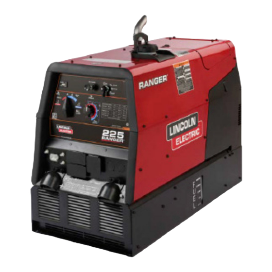
RANGER
225
For use with machines having Code Numbers:
11597, 11734, 11790, 11797
SERVICE MANUAL
SVM220-A
| Issue D ate 12-Apr
© Lincoln Global, Inc. All Rights Reserved.
Need Help? Call 1.888.935.3877
to talk to a Service Representative
Hours of Operation:
8:00 AM to 6:00 PM (ET) Mon. thru Fri.
After hours?
Use "Ask the Experts" at lincolnelectric.com
A Lincoln Service Representative will contact you
no later than the following business day.
For Service outside the USA:
Email: globalservice@lincolnelectric.com
Advertisement
Chapters
Table of Contents
Troubleshooting

Related Manuals for Lincoln Electric RANGER 225


Summary of Contents for Lincoln Electric RANGER 225
- Page 1 ® RANGER For use with machines having Code Numbers: 11597, 11734, 11790, 11797 SERVICE MANUAL Need Help? Call 1.888.935.3877 to talk to a Service Representative Hours of Operation: 8:00 AM to 6:00 PM (ET) Mon. thru Fri. After hours? Use “Ask the Experts” at lincolnelectric.com A Lincoln Service Representative will contact you no later than the following business day.
- Page 2 351040, Miami, Florida 33135 or CSA Standard W117.2-1974. A Free copy of “Arc Welding Safety” booklet E205 is available from the Lincoln Electric Company, 22801 St. Clair Avenue, Cleveland, Ohio 44117-1199. BE SURE THAT ALL INSTALLATION, OPERATION, MAINTENANCE AND REPAIR PROCEDURES ARE PERFORMED ONLY BY QUALIFIED INDIVIDUALS.
- Page 3 SAFETY ELECTRIC SHOCK can kill. ARC RAYS can burn. 3.a. The electrode and work (or ground) circuits 4.a. Use a shield with the proper filter and cover plates to protect your eyes from sparks and are electrically “hot” when the welder is on. the rays of the arc when welding or observing Do not touch these “hot”...
- Page 4 SAFETY WELDING and CUTTING CYLINDER may explode SPARKS can cause fire or if damaged. 7.a. Use only compressed cylinders explosion. containing the correct shielding gas for the 6.a. Remove fire hazards from the welding area. process used and properly operating If this is not possible, cover them to prevent the regulators designed for the gas and welding sparks from starting a fire.
- Page 5 SAFETY zones où l’on pique le laitier. PRÉCAUTIONS DE SÛRETÉ 6. Eloigner les matériaux inflammables ou les recouvrir afin de Pour votre propre protection lire et observer toutes les instructions et prévenir tout risque d’incendie dû aux étincelles. les précautions de sûreté specifiques qui parraissent dans ce man- uel aussi bien que les précautions de sûreté...
- Page 6 2004/108/EC. It was manufactured in conformity with a national standard that implements a harmonized standard: EN 60974-10 Electromagnetic Compatibility (EMC) Product Standard for Arc Welding Equipment. It is for use with other Lincoln Electric equipment. It is designed for industrial and professional use. Introduction All electrical equipment generates small amounts of electromagnetic emission.
- Page 7 SAFETY Electromagnetic Compatibility (EMC) The size of the surrounding area to be considered will depend on the structure of the building and other activities that are taking place. The surrounding area may extend beyond the boundaries of the premises. Methods of Reducing Emissions Mains Supply Welding equipment should be connected to the mains supply according to the manufacturer’s recommen- dations.
- Page 8 - MASTER TABLE OF CONTENTS FOR ALL SECTIONS - RETURN TO MAIN INDEX Page Safety ................i-vi Installation .
-
Page 9: Table Of Contents
Electrical Device Used with the Ranger 225 ........ - Page 10 INSTALLATION TECHNICAL SPECIFICATIONS - RANGER® 225 ( K2857-1) INPUT - GASOLINE ENGINE Description Operating Capacities Make/Model Starting Horsepower Speed (RPM) System 2 cylinder High Idle 3700 12VDC 4 Cycle Battery Kohler Air-Cooled Fuel: CH23S, Electric Gasoline Start 12 Gal (45.4 L) CH680 Full Load 3500 23 HP @...
-
Page 11: Installation
INSTALLATION SAFETY PRECAUTIONS When this welder is mounted on a truck or trailer, its frame must be electrically bonded to the metal frame WARNING of the vehicle. Use a #8 or larger copper wire con- nected between the machine grounding stud and the Do not attempt to use this equipment until you have frame of the vehicle. -
Page 12: Vehicle Mounting
INSTALLATION 3. Proper placement of the equipment on the trailer to FUEL insure stability side to side and front to back when being moved and when standing by itself while being operated or serviced. Fill the fuel tank with clean, fresh, lead-free gasoline. Observe fuel gauge while filling to prevent overfilling. -
Page 13: Welding Output Cables
INSTALLATION WELDING OUTPUT CABLES ADDITIONAL SAFETY PRECAUTION With the engine off, connect the electrode and work WARNING cables to the studs provided. These connections should be checked periodically and tightened if nec- essary. Loose connections will result in overheating of the output studs. -
Page 14: Location And Ventilation
• Shut the welder off. The TIG Module is an accessory that provides high fre- • Connect the cable from the ALTIU8 to Ranger 225. quency and shielding gas control for DC GTAW (TIG) Connect to the appropriate terminal, either DC(+) or welding. - Page 15 INSTALLATION WELDER OPERATION 120/240 VOLT DUAL VOLTAGE RECEPTACLE The 120/240 volt receptacle can supply up to 38 amps WELDER OUTPUT of 240 volt power to a two wire circuit, up to 38 amps • Maximum Open Circuit Voltage at 3700 RPM is 80 of 120 volts power from each side of a three wire cir- Volts RMS.
- Page 16 DO NOT USE THESE DEVICES WITH A RANGER ® The Lincoln Electric Company is not responsible for any damage to electrical components improperly connected to the RANGER 225. ® RANGER ®...
- Page 17 INSTALLATION ------------------------------------------------------------- AUXILIARY POWER WHILE WELDING 1. Install a double pole, double throw switch between Simultaneous welding and power loads are permit- the power company meter and the premises dis- ted by following Table A.5. The permissible currents connect. shown assume that current is being drawn from either Switch rating must be the same or greater than the 120V or 240V supply (not both at the same time).
- Page 18 INSTALLATION A-10 A-10 – FIGURE A.2 CONNECTION OF RANGER 225 TO PREMISES WIRING ® WARNING Connection of RANGER 225 to premises wiring ® must be done by a licensed electrician and must comply with the National Electrical Code and all other applicable electrical codes.
- Page 19 TABLE OF CONTENTS - OPERATION SECTION Operation ................B-1 Safety Precautions .
-
Page 20: Operation
OPERATION SAFETY PRECAUTIONS WELDER CONTROLS - FUNCTION AND OPERATION Do not attempt to use this equipment until you have thoroughly read the engine manufacturer’s manual supplied with your welder. It includes ENGINE SWITCH important safety precautions, detailed engine starting, operating and maintenance instructions, The engine switch is used to Start the Engine, Select and parts lists. - Page 21 OPERATION “ RANGE” SWITCH The “Range” switch is used to select one of four amperage ranges with generous overlap for Stick/TIG welding, or one Wire Feed welding range. TABLE B.1 – RANGE SWITCH SETTINGS Process Range Setting Current Range STICK/TIG 90 Max.
-
Page 22: Starting/Shutdown Instructions
OPERATION STARTING/SHUTDOWN INSTRUCTIONS STOPPING THE ENGINE STARTING THE ENGINE Remove all welding and auxiliary power loads and allow engine to run at low idle speed for a few minutes WARNING to cool the engine. Stop the engine by placing the Engine switch in the •... -
Page 23: Welding Process
OPERATION The RANGER® 225 can be used with a broad range WELDING PROCESS of DC stick electrodes. See “Welding Tips 1” includ- For any electrodes the procedures should be kept ed with the RANGER® 225 for electrodes within the within the rating of the machine. For electrode infor- rating of this unit and recommended welding currents mation see the appropriate Lincoln publication. - Page 24 OPERATION WIRE FEED WELDING PROCESSES ARC GOUGING (CONSTANT VOLTAGE) The RANGER 225 can be used for limited arc gouging. ® ® electrode recommended for use with The Innershield Set the Range switch to adjust output current to the ® the RANGER® 225 is NR -211-MP.
- Page 25 TABLE OF CONTENTS - ACCESSORIES SECTION Accessories ................C-1 Optional Equipment .
- Page 26 ACCESSORIES OPTIONAL EQUIPMENT K875 Accessory Kit - For Stick welding. Includes (Field Installed) 20ft.(6.1m)#6 electrode cable with lug. 15ft.(4.6m)#6 K2635-1 SMALL TWO-WHEEL ROAD TRAILER work cable with lugs, headshield, filter plate, work WITH DUO-HITCH - For heavy-duty road, off-road, clamp, electrode holder and sample pack of mild steel plant and yard use.
- Page 27 ACCESSORIES RECOMMENDED EQUIPMENT Optional TIG Equipment: K939-1 Docking Kit - For Mounting the K930-2 TIG STICK Module on top of the RANGER 225. ® K704 Accessory Kit - (400 AMP Capacity) which K937-45 Control Cable Extension - Allows TIG Module includes: to be operated at distances up to 200ft.
- Page 28 NOTES RANGER ®...
- Page 29 TABLE OF CONTENTS - MAINTENANCE SECTION Maintenance ................D-1 Service Instructions .
-
Page 30: Maintenance
MAINTENANCE RANGER ®... -
Page 31: Safety Precautions
MAINTENANCE SAFETY PRECAUTIONS CAUTION WARNING Make certain that the oil filler cap is securely tight- Have qualified personnel do the maintenance work. ened after checking or adding oil. If the cap is not Turn the engine off before working inside the tight, oil consumption can increase significantly machine. -
Page 32: Oil Filter Change
MAINTENANCE Use 4-stroke motor oil that meets or exceeds the AIR CLEANER AND OTHER requirements for API service classification SG or SH. MAINTENANCE Always check the API SERVICE label on the oil con- • Air Cleaner - With normal operating conditions, the tainer to be sure it includes the letters SG or SH. -
Page 33: Engine Adjustments
MAINTENANCE ENGINE ADJUSTMENTS WARNING GASES FROM BATTERY can explode. OVERSPEED IS HAZARDOUS • Keep sparks, flame and cigarettes away from battery. To prevent EXPLOSION when: WARNING • INSTALLING A NEW BATTERY - disconnect nega- tive cable from old battery first and connect to new battery last. - Page 34 MAINTENANCE FIGURE D.1 MAJOR COMPONENT LOCATIONS 1. Case Front Assembly 2. Control Panel Assembly 3. Base / Fuel Tank / Battery Assembly 4. Engine Assembly 5. Blower Baffle Assembly 6. Stator / Rotor Assembly 7. Covers & Case Back Assembly RANGER ®...
- Page 35 TABLE OF CONTENTS-THEORY OF OPERATION SECTION Theory of Operation ..............E-1 Battery, Engine Starting, Engine Stopping and Idle System .
-
Page 36: Battery
THEORY OF OPERATION FIGURE E.2 - BATTERY, ENGINE STARTING, STOPPING AND IDLE SYSTEM CHARGING SYSTEM – CV TOP WELD ROTOR WINDING FUEL SOLENOID OIL PRESSURE SWITCH EXCITATION AUXILIARY POWER STARTER MOTOR WINDING WINDING IDLE REACTOR STARTER SOLENOID SOLENOID SELECTOR SWITCH ENGINE CURRENT FIELD... - Page 37 THEORY OF OPERATION BATTERY, ENGINE STARTING, STOPPING AND IDLE SYSTEM (continued) When no output current is detected, the idle control circuit delays for about 12 seconds, then it connects the negative terminal of the solenoid to chassis ground. If the engine switch is in the auto idle posi- tion, this activates the solenoid and pulls the engine to low idle RPM.
- Page 38 THEORY OF OPERATION FIGURE E.3 - FLASHING, ALTERNATOR BUILD-UP, FINE CURRENT CONTROL AND AUXILIARY POWER CHARGING SYSTEM – CV TOP WELD ROTOR WINDING FUEL SOLENOID OIL PRESSURE SWITCH EXCITATION AUXILIARY POWER STARTER MOTOR WINDING WINDING IDLE REACTOR STARTER SOLENOID SOLENOID SELECTOR SWITCH ENGINE...
- Page 39 THEORY OF OPERATION FIGURE E.4 - WELD WINDING, REACTOR, RANGE SELECTOR SWITCH, OUTPUT RECTIFIER, CHOKE AND OUTPUT TERMINALS CHARGING SYSTEM – CV TOP WELD ROTOR WINDING FUEL SOLENOID OIL PRESSURE SWITCH EXCITATION AUXILIARY POWER STARTER MOTOR WINDING WINDING IDLE REACTOR STARTER SOLENOID SOLENOID SELECTOR...
- Page 40 NOTES RANGER ®...
- Page 41 TABLE OF CONTENTS - TROUBLESHOOTING AND REPAIR Troubleshooting and Repair ............. . F-1 How to Use Troubleshooting Guide .
-
Page 42: How To Use Troubleshooting Guide
HOW TO USE TROUBLESHOOTING GUIDE WARNING Service and Repair should only be performed by Lincoln Electric Factory Trained Personnel. Unauthorized repairs performed on this equipment may result in danger to the technician and machine operator and will invalidate your factory warranty. For your safety and to avoid Electrical Shock, please observe all safety notes and precautions detailed throughout this manual. -
Page 43: Pc Board Troubleshooting Procedures
Do not touch electrically hot parts. - If you return a PC board to The Lincoln Electric Company for credit, it must be in the static-shield- ing bag. This will prevent further damage and allow CAUTION proper failure analysis. - Page 44 Replace. CAUTION If for any reason you do not understand the test procedures or are unable to perform the tests/repairs safely, contact the Lincoln Electric Service Department for technical troubleshooting assistance before you proceed. Call 1-888-935-3877. RANGER...
- Page 45 5. Perform the Output Rectifier Bridge Test. CAUTION If for any reason you do not understand the test procedures or are unable to perform the tests/repairs safely, contact the Lincoln Electric Service Department for technical troubleshooting assistance before you proceed. Call 1-888-935-3877. RANGER ®...
- Page 46 CAUTION If for any reason you do not understand the test procedures or are unable to perform the tests/repairs safely, contact the Lincoln Electric Service Department for technical troubleshooting assistance before you proceed. Call 1-888-935-3877. RANGER ®...
- Page 47 CAUTION If for any reason you do not understand the test procedures or are unable to perform the tests/repairs safely, contact the Lincoln Electric Service Department for technical troubleshooting assistance before you proceed. Call 1-888-935-3877. RANGER ®...
- Page 48 CAUTION If for any reason you do not understand the test procedures or are unable to perform the tests/repairs safely, contact the Lincoln Electric Service Department for technical troubleshooting assistance before you proceed. Call 1-888-935-3877. RANGER ®...
- Page 49 See Wiring Dia- gram. CAUTION If for any reason you do not understand the test procedures or are unable to perform the tests/repairs safely, contact the Lincoln Electric Service Department for technical troubleshooting assistance before you proceed. Call 1-888-935-3877. RANGER ®...
- Page 50 CAUTION If for any reason you do not understand the test procedures or are unable to perform the tests/repairs safely, contact the Lincoln Electric Service Department for technical troubleshooting assistance before you proceed. Call 1-888-935-3877. RANGER ®...
- Page 51 Replace. CAUTION If for any reason you do not understand the test procedures or are unable to perform the tests/repairs safely, contact the Lincoln Electric Service Department for technical troubleshooting assistance before you proceed. Call 1-888-935-3877. RANGER ®...
- Page 52 Replace if necessary. CAUTION If for any reason you do not understand the test procedures or are unable to perform the tests/repairs safely, contact the Lincoln Electric Service Department for technical troubleshooting assistance before you proceed. Call 1-888-935-3877. RANGER ®...
- Page 53 See Wiring Diagram. CAUTION If for any reason you do not understand the test procedures or are unable to perform the tests/repairs safely, contact the Lincoln Electric Service Department for technical troubleshooting assistance before you proceed. Call 1-888-935-3877. RANGER ®...
- Page 54 NOTES F-14 F-14 RANGER ®...
-
Page 55: Case Cover Removal And Replacement Procedure
CASE COVER REMOVAL AND REPLACEMENT PROCEDURE WARNING Service and repair should be performed only by Lincoln Electric factory trained per- sonnel. Unauthorized repairs performed on this equipment may result in danger to the technician or machine operator and will invalidate your factory warranty. For your safety and to avoid electrical shock, please observe all safety notes and precautions detailed throughout this manual. - Page 56 TROUBLESHOOTING AND REPAIR F-16 F-16 CASE COVER REMOVAL AND REPLACEMENT PROCEDURE (continued) FIGURE F.1 – CASE COVER ASSEMBLY CASE COVER ASSEMBLY REMOVAL PROCEDURE 1. Remove the Right Engine Cover by opening the latch and sliding it off of the hinge pins toward the rear (engine end) of the machine.
- Page 57 TROUBLESHOOTING AND REPAIR F-17 F-17 CASE COVER REMOVAL AND REPLACEMENT PROCEDURE (continued) REPLACEMENT PROCEDURE 1. Replace the case sides by reversing the remov- 5. Start the remaining screws, and then tighten all al procedure. Start the three screws across the of the screws in the Roof and Sides.
- Page 58 NOTES F-18 F-18 RANGER ®...
-
Page 59: Rotor Voltage Test
ROTOR VOLTAGE TEST WARNING Service and repair should be performed only by Lincoln Electric factory trained per- sonnel. Unauthorized repairs performed on this equipment may result in danger to the technician or machine operator and will invalidate your factory warranty. For your safety and to avoid electrical shock, please observe all safety notes and precautions detailed throughout this manual. - Page 60 TROUBLESHOOTING AND REPAIR F-20 F-20 ROTOR VOLTAGE TEST (continued) FIGURE F.2 – LOCATION OF LEAD 200A AND 219 FOR ROTOR VOLTAGE TEST Brushes Slip Rings Lead 200A Lead 219 PROCEDURE 1. Perform the Case Cover Removal Procedure. 8. If the voltage reading is normal, the field circuit is functioning properly.
-
Page 61: Rotor Resistance Test
ROTOR RESISTANCE TEST WARNING Service and repair should be performed only by Lincoln Electric factory trained per- sonnel. Unauthorized repairs performed on this equipment may result in danger to the technician or machine operator and will invalidate your factory warranty. For your safety and to avoid electrical shock, please observe all safety notes and precautions detailed throughout this manual. - Page 62 TROUBLESHOOTING AND REPAIR F-22 F-22 ROTOR RESISTANCE TEST (continued) FIGURE F.3 – LOCATION OF ROTOR SLIP RINGS Lead 200A Lead 219 PROCEDURE 6. Measure the resistance to ground. A. Set the ohmmeter on the high scale 1. Perform the Case Cover Removal Procedure. (X100,000).
-
Page 63: Auxiliary Winding Test
AUXILIARY WINDING TEST WARNING Service and repair should be performed only by Lincoln Electric factory trained per- sonnel. Unauthorized repairs performed on this equipment may result in danger to the technician or machine operator and will invalidate your factory warranty. For your safety and to avoid electrical shock, please observe all safety notes and precautions detailed throughout this manual. - Page 64 TROUBLESHOOTING AND REPAIR F-24 F-24 AUXILIARY WINDING TEST (continued) FIGURE F.4 – LOCATION OF LEADS #3 AND #5 Machine Case 115V Front Receptacle Lead #3D or #6E Lead #5A or #5B PROCEDURE To test the 120 VAC winding: To test the 240 VAC winding: 1.
- Page 65 OUTPUT RECTIFIER BRIDGE TEST WARNING Service and repair should be performed only by Lincoln Electric factory trained per- sonnel. Unauthorized repairs performed on this equipment may result in danger to the technician or machine operator and will invalidate your factory warranty. For your safety and to avoid electrical shock, please observe all safety notes and precautions detailed throughout this manual.
- Page 66 TROUBLESHOOTING AND REPAIR F-26 F-26 OUTPUT RECTIFIER BRIDGE TEST (continued) FIGURE F.5 – LOCATION OF OUTPUT RECTIFIER LEADS NEGATIVE (-) OUTPUT POSITIVE (+) OUTPUT AC INPUT AC-1 & AC-2 OUTPUT RECTIFIER PROCEDURE TABLE F.1 – RECTIFIER TERMINAL CONNECTIONS 1. Remove the spark plug wires to prevent acci- Test Instument dental engine kickback or starting.
-
Page 67: Charging Circuit Test
CHARGING CIRCUIT TEST WARNING Service and repair should be performed only by Lincoln Electric factory trained per- sonnel. Unauthorized repairs performed on this equipment may result in danger to the technician or machine operator and will invalidate your factory warranty. For your safety and to avoid electrical shock, please observe all safety notes and precautions detailed throughout this manual. - Page 68 TROUBLESHOOTING AND REPAIR F-28 F-28 CHARGING CIRCUIT TEST (continued) FIGURE F.6 – LOCATION OF VOLTAGE REGULATOR Engine Voltage Regulator AC Lead DC Lead AC Lead PROCEDURE 1. Start the engine and run it at high idle (3650 5. If the DC voltage reading is incorrect or not RPM).
-
Page 69: Engine Throttle Adjustment Test
ENGINE THROTTLE ADJUSTMENT TEST WARNING Service and repair should be performed only by Lincoln Electric factory trained per- sonnel. Unauthorized repairs performed on this equipment may result in danger to the technician or machine operator and will invalidate your factory warranty. For your safety and to avoid electrical shock, please observe all safety notes and precautions detailed throughout this manual. - Page 70 TROUBLESHOOTING AND REPAIR F-30 F-30 ENGINE THROTTLE ADJUSTMENT TEST (continued) FIGURE F.7 – BLOWER PADDLE MARKED FOR STROBE-TACH METHOD Blower Paddle PROCEDURE 5. Connect the strobe-tach according the manu- This test can be conducted by any one of four facturer’s instructions. methods.
- Page 71 TROUBLESHOOTING AND REPAIR F-31 F-31 ENGINE THROTTLE ADJUSTMENT TEST (continued) FIGURE F.8 – HIGH IDLE ADJUSTMENT NUT FIGURE F.9 – LOW IDLE ADJUSTMENT NUT Solenoid 3/8" Low Idle Adjustment Muffler Housing Throttle linkage Choke Cable 3/8" High Idle Adjustment Nut 9.
- Page 72 TROUBLESHOOTING AND REPAIR F-32 F-32 ENGINE THROTTLE ADJUSTMENT TEST (continued) Vibratach Method: 1. Place the vibratach as close to the engine as possible, the top of the air cleaner is the best location. 2. Start the engine and observe the whip handle of the vibratach.
- Page 73 TROUBLESHOOTING AND REPAIR F-33 F-33 NORMAL OPEN CIRCUIT VOLTAGE WAVEFORM (120 VAC SUPPLY) HIGH IDLE – NO LOAD – OUTPUT CONTROL AT MAXIMUM 16.2 ms 0 volts 50 Volts This is the typical AC output voltage generated from a properly operating machine.
- Page 74 TROUBLESHOOTING AND REPAIR F-34 F-34 TYPICAL DC WELD OUTPUT WAVEFORM (CV MODE) MACHINE LOADED 0 volts 20 Volts MACHINE LOADED TO 200 AMPS AT 20 VDC This is the typical CV output voltage generated from a properly operating machine. Note that each vertical divi- sion represents 20 volts and that each horizontal division represents 5 mil- liseconds in time.
- Page 75 TROUBLESHOOTING AND REPAIR F-35 F-35 TYPICAL DC WELD OUTPUT WAVEFORM (CC MODE) MACHINE LOADED 0 volts 20 Volts MACHINE LOADED TO 200 AMPS AT 26 VDC This is the typical DC output voltage generated from a properly operating machine. Note that each vertical divi- sion represents 20 volts and that each horizontal division represents 5 mil- liseconds in time.
- Page 76 TROUBLESHOOTING AND REPAIR F-36 F-36 ABNORMAL OPEN CIRCUIT WELD VOLTAGE WAVEFORM (CV MODE) HIGH IDLE - NO LOAD - OUTPUT CONTROL AT MAXIMUM ONE OUTPUT DIODE GROUP NOT FUNCTIONING 0 volts 20 Volts This is NOT the typical CV output volt- age waveform.
- Page 77 TROUBLESHOOTING AND REPAIR F-37 F-37 ABNORMAL OPEN CIRCUIT DC WELD VOLTAGE WAVEFORM HIGH IDLE - NO LOAD - OUTPUT CONTROL AT MAXIMUM ONE OUTPUT DIODE GROUP NOT FUNCTIONING 0 volts 50 Volts This is NOT the typical DC (+) output voltage waveform.
- Page 78 TROUBLESHOOTING AND REPAIR F-38 F-38 NORMAL OPEN CIRCUIT WELD VOLTAGE WAVEFORM (CV MODE) HIGH IDLE - NO LOAD - OUTPUT CONTROL AT MAXIMUM 0 volts 20 Volts This is the typical CV output voltage generated from a properly operating machine. Note that each vertical division represents 20 volts and that each horizontal division represents 5...
- Page 79 TROUBLESHOOTING AND REPAIR F-39 F-39 NORMAL OPEN CIRCUIT DC WELD VOLTAGE WAVEFORM (CC MODE) HIGH IDLE - NO LOAD - OUTPUT CONTROL AT MAXIMUM 0 volts 50 Volts This is the typical DC output voltage generated from a properly operating machine.
- Page 80 NOTES F-40 F-40 RANGER ®...
- Page 81 BRUSH REMOVAL AND REPLACEMENT PROCEDURE WARNING Service and repair should be performed only by Lincoln Electric factory trained per- sonnel. Unauthorized repairs performed on this equipment may result in danger to the technician or machine operator and will invalidate your factory warranty. For your safety and to avoid electrical shock, please observe all safety notes and precautions detailed throughout this manual.
- Page 82 TROUBLESHOOTING AND REPAIR F-42 F-42 BRUSH REMOVAL AND REPLACEMENT PROCEDURE (continued) REMOVAL PROCEDURE REPLACEMENT PROCEDURE 1. Remove the spark plug wires. 9. To reinstall the Brushes, depress the spring-load- ed Brushes into the holder and slip a suitable 2. Perform the Case Cover Removal Procedure. non-metallic, fairly stiff retainer through the 3.
- Page 83 TROUBLESHOOTING AND REPAIR F-43 F-43 BRUSH REMOVAL AND REPLACEMENT PROCEDURE (continued) FIGURE F.10 – BRUSH LEADS / BRUSHES RETAINED WITH CABLE TIES Cable Brushes 7/16" Brush Assembly Bracket Bolts SLIP RINGS A slight amount of darkening and wear of the Slip CAUTION Rings and Brushes is normal.
- Page 84 NOTES F-44 F-44 RANGER ®...
- Page 85 REMOVAL AND REPLACEMENT PROCEDURE WARNING Service and repair should be performed only by Lincoln Electric factory trained per- sonnel. Unauthorized repairs performed on this equipment may result in danger to the technician or machine operator and will invalidate your factory warranty. For your safety and to avoid electrical shock, please observe all safety notes and precautions detailed throughout this manual.
- Page 86 TROUBLESHOOTING AND REPAIR F-46 F-46 PRINTED CIRCUIT BOARD REMOVAL AND REPLACEMENT PROCEDURE (continued) FIGURE F.11 – PRINTED CIRCUIT BOARD LOCATION 4 Self Tapping Screws (at corners) 12 Pin Plug 1/4" Q.C. Tabs 4 Pin Plug REMOVAL PROCEDURE Before starting the following procedure, refer to the topic PC Board Troubleshooting Procedures at the beginning of this section.
- Page 87 TROUBLESHOOTING AND REPAIR F-47 F-47 PRINTED CIRCUIT BOARD REMOVAL AND REPLACEMENT PROCEDURE (continued) CAUTION Be sure to follow the recommended static-free methods for handling Printed Circuit Boards. Failure to do so can result in permanent damage to the equipment. REPLACEMENT PROCEDURE 1.
- Page 88 NOTES F-48 F-48 RANGER ®...
- Page 89 OUTPUT RECTIFIER REMOVAL AND REPLACEMENT PROCEDURE WARNING Service and repair should be performed only by Lincoln Electric factory trained per- sonnel. Unauthorized repairs performed on this equipment may result in danger to the technician or machine operator and will invalidate your factory warranty. For your safety and to avoid electrical shock, please observe all safety notes and precautions detailed throughout this manual.
- Page 90 TROUBLESHOOTING AND REPAIR F-50 F-50 OUTPUT RECTIFIER REMOVAL AND REPLACEMENT PROCEDURE (continued) FIGURE F.12 – OUTPUT RECTIFIER CONNECTIONS NEGATIVE (-) OUTPUT POSITIVE (+) OUTPUT AC INPUT AC-1 & AC-2 OUTPUT RECTIFIER REMOVAL PROCEDURE REPLACEMENT PROCEDURE 1. Remove the engine spark plug wires. 1.
- Page 91 ENGINE / ROTOR REMOVAL AND REPLACEMENT PROCEDURE WARNING Service and repair should be performed only by Lincoln Electric factory trained per- sonnel. Unauthorized repairs performed on this equipment may result in danger to the technician or machine operator and will invalidate your factory warranty. For your safety and to avoid electrical shock, please observe all safety notes and precautions detailed throughout this manual.
- Page 92 TROUBLESHOOTING AND REPAIR F-52 F-52 ENGINE / ROTOR REMOVAL AND REPLACEMENT PROCEDURE (continued) FIGURE F.13 – COMPONENT LOCATIONS, ENGINE / ROTOR REMOVAL 1. STATOR COWLING COVER 2. BLOWER FAN 3. IDLE LINKAGE 4. BRUSH HOLDER BRACKET 5. ENGINE LIFT BAILS 6.
- Page 93 TROUBLESHOOTING AND REPAIR F-53 F-53 ENGINE / ROTOR REMOVAL AND REPLACEMENT PROCEDURE (continued) ENGINE AND ROTOR REMOVAL PROCEDURE 1. Refer to Figure F.13 for component locations. 16. Using a 9/16” wrench, remove the four bolts that hold the stator to the engine. There is one 2.
- Page 94 Be careful not to lose the washer that fits 3. Install the appropriate long thru-bolt (two are between the blower fan and the Rotor. provided) supplied with Lincoln Electric Rotor Removal Kit S20788. The slot head must face out. Screw in the bolt with the slot head screw driver until the bolt bottoms out on the Engine crankshaft, about 3/4”.
- Page 95 ENGINE / ROTOR REMOVAL AND REPLACEMENT PROCEDURE (continued) REPLACEMENT PROCEDURE NOTE: Lincoln Electric recommends that a new 9. Attach leads to the oil pressure switch refer to bearing (Lincoln part #M9300-85) and a Wiring Diagram. Replace any cut cable ties.
- Page 96 TROUBLESHOOTING AND REPAIR F-56 F-56 RETEST AFTER REPAIR Retest a machine: • If it is rejected under test for any reason that requires you to remove any mechanical part which could affect the machine’s electrical characteristics. • If you repair or replace any electrical components. ENGINE OUTPUT Mode No Load RPM...
- Page 97 TABLE OF CONTENTS - DIAGRAM SECTION Electrical Diagrams ..............G-1 Wiring Diagram (M22194) .
-
Page 98: Electrical Diagrams
ELECTriCaL DiaGramS WiriNG DiaGram - (m22194) RANGER 225 LEADS 3 AND 6: 2 TURNS THRU TOROID IN OPPOSITE DIRECTIONS 1 TURN 1 2 3 4 ENGINE CONTROL SWITCH X X X AUTO HIGH START OUTPUT X= CLOSED CIRCUIT IDLER CONTROL... -
Page 99: Schematic - Complete Machine (L15165
ELECTriCaL DiaGramS SChEmaTiC - COmpLETE maChiNE (L15165) ENGINEERING CONTROLLED CHANGE DETAIL: ADDED MISC. NOTES. MANUFACTURER: STATOR WELD Choke mounted on base in POSITIVE 33 TO 37 VAC BETWEEN W1 WINDINGS front of generator. 225 Max AND C1 AT HIGH IDLE AND TERMINAL L1 CHOKE D1 - BRIDGE RECTIFIER... -
Page 100: Schematic - Idler Pc Board (L12197
ELECTriCaL DiaGramS SChEmaTiC - iDLEr pC bOarD (L12197) NOTE: This diagram is for reference only. It may not be accurate for all machines covered by this manual. raNGEr ®...
Need help?
Do you have a question about the RANGER 225 and is the answer not in the manual?
Questions and answers