Table of Contents
Advertisement
Quick Links
PIPELINER
200
®
For use with machines having Code Numbers:
11114, 11316, 11471, 11498, 11591, 11644
10929, 10660, 10913, 11136
SERVICE MANUAL
SVM193-A
| Issue D ate 09-Jul
© Lincoln Global, Inc. All Rights Reserved.
NOTE: This manual will cover most of the troubleshooting and repair
procedures for the code numbers listed. Some variances may exist when
troubleshooting/repairing later code numbers.
Advertisement
Chapters
Table of Contents
Troubleshooting

Related Manuals for Lincoln Electric PIPELINER 200


Summary of Contents for Lincoln Electric PIPELINER 200
- Page 1 NOTE: This manual will cover most of the troubleshooting and repair procedures for the code numbers listed. Some variances may exist when troubleshooting/repairing later code numbers. PIPELINER ® For use with machines having Code Numbers: 11114, 11316, 11471, 11498, 11591, 11644 10929, 10660, 10913, 11136 SERVICE MANUAL SVM193-A...
-
Page 2: Safety
Miami, Florida 33135 or CSA Standard W117.2-1974. A Free copy of “Arc Welding Safety” booklet E205 is available from the Lincoln Electric Company, 22801 St. Clair Avenue, Cleveland, Ohio 44117-1199. BE SURE THAT ALL INSTALLATION, OPERATION, MAINTENANCE AND REPAIR PROCEDURES ARE PERFORMED ONLY BY QUALIFIED INDIVIDUALS. - Page 3 SAFETY ELECTRIC SHOCK can kill. ARC RAYS can burn. 3.a. The electrode and work (or ground) circuits 4.a. Use a shield with the proper filter and cover are electrically “hot” when the welder is on. plates to protect your eyes from sparks and Do not touch these “hot”...
- Page 4 SAFETY WELDING and CUTTING CYLINDER may explode SPARKS can cause fire or if damaged. explosion. 7.a. Use only compressed cylinders containing the correct shielding gas for the 6.a. Remove fire hazards from the welding area.If process used and properly operating this is not possible, cover them to prevent the welding sparks regulators designed for the gas and from starting a fire.
- Page 5 SAFETY PRÉCAUTIONS DE SÛRETÉ 6. Eloigner les matériaux inflammables ou les recouvrir afin de prévenir tout risque dʼincendie dû aux étincelles. Pour votre propre protection lire et observer toutes les instructions 7. Quand on ne soude pas, poser la pince à une endroit isolé de et les précautions de sûreté...
-
Page 6: Table Of Contents
- MASTER TABLE OF CONTENTS FOR ALL SECTIONS - Page Safety ................i-iv Installation (Kubota V2203M) (K6090-11) . - Page 7 TABLE OF CONTENTS - INSTALLATION SECTION Installation ................A-1 Technical Specifications .
-
Page 8: Installation (Kubota V2203M) (K6090-11)
INSTALLATION TECHNICAL SPECIFICATIONS - PIPELINER® 200D KUBOTA (K6090-11) INPUT - DIESEL ENGINE Make/Model Description Speed (RPM) Displacement Starting Capacities System 4 Cylinder 4 Cycle 134.1 cu. in 12VDC battery Fuel: 15 gal Naturally Aspirated (2.2 ltrs) (Group 45, 650 57 L Kubota Water-Cooled High Idle 1600... -
Page 9: Installation (Perkins 104.22) (K6090-9)
INSTALLATION GENERAL DESCRIPTION ENGINE IDLER The Pipeliner® 200D KUBOTA is equipped with an electronic automatic engine idler. It automatically The Pipeliner® 200D is a heavy duty engine driven DC increases and decreases engine speed when starting arc welding power source capable of providing DC and stopping welding or using auxiliary power. - Page 10 INSTALLATION PRE-OPERATION INSTALLATION CAUTION WARNING DO NOT MOUNT OVER COMBUSTIBLE SUR- FACES. Do not attempt to use this equipment until you Where there is a combustible surface directly under have thoroughly read the engine manufacturerʼs stationary or fixed electrical equipment, the surface manual supplied with your welder.
- Page 11 INSTALLATION TRAILER (See Accessories Section) RECOMMENDED COPPER CABLE SIZES Cables Sizes for Combined Length of Electrode Plus Work Cable If the user adapts a non-Lincoln trailer, the user must Amps Duty Cycle Up to 200ft.(61m) 200 to 250ft. assume responsibility that the method of attachment (61 to 76m) and usage does not result in a safety hazard nor dam- age the welding equipment.
-
Page 12: Installation (Gm 3.0 L) (K6090-7)
INSTALLATION Battery Charging WARNING GASES FROM BATTERY can explode. • Keep sparks, flame and cigarettes away. BATTERY ACID can burn eyes and skin. • Wear gloves and eye protection and be careful when boosting, charging or working near battery. To prevent EXPLOSION when: a) Installing a new battery - disconnect the nega- tive cable from the old battery first and con- nect the negative cable to the new battery last... - Page 13 TABLE OF CONTENTS - OPERATION SECTION Operation ................B-1 Engine Operation .
-
Page 14: Operation (Kubota V2203M) (K6090-11)
5. Observe the oil pressure. If no pressure shows within 30 seconds, stop the engine and consult the engine operating manual. To stop the engine, turn the “IGNI- Lincoln Electric selects high quality, heavy-duty indus- TION” switch to “OFF”. trial engines for the portable welding machines we 6. -
Page 15: Operation (Perkins 104.22) (K6090-9)
OPERATION DUTY CYCLE Larger machines with a capacity of 350 amperes and higher, which are operated at low or no-load conditions for extended periods of time are especially susceptible The NEMA output rating of the PIPELINER® 200D to the conditions described above. To accomplish suc- KUBOTA is 200 amperes at 28 arc volts on a 60% duty cessful engine break-in, most diesel-powered equip- cycle (consult Specifications in this manual for alternate... - Page 16 OPERATION IDLER OPERATION Start the engine with the “Idler” switch in the “High” position. Allow it to run at high idle speed for several minutes to warm the engine. See Specifications for operating speeds. The idler is controlled by the “Idler” toggle switch on the welder control panel.
- Page 17 TABLE OF CONTENTS - ACCESSORIES SECTION Accessories ................C-1 Optional Features .
- Page 18 LN-23P Wire Feeder (K316L-1)-Portable CV unit for for pipe thawing is not approved by the CSA, nor is Innershield pipe welding. Control cable operates con- it recommended or supported by Lincoln Electric. tactor inside Wire Feed Module for “cold” electrode. ------------------------------------------------------------------------...
- Page 19 TABLE OF CONTENTS - MAINTENANCE SECTION Maintenance ................D-1 Safety Precautions, Bearings, Commutator &...
- Page 20 MAINTENANCE SAFETY PRECAUTIONS 4. When necessary, remove the sediment bowl, if so equipped, from beneath the fuel tank and clean WARNING out any accumulated dirt and water. Have qualified personnel do the maintenance Follow the engine service schedule in this manual work.
- Page 21 MAINTENANCE P U R G I N G A I R F R O M F U E L S Y S T E M Replace brushes when they wear within 1/4”(3.5mm) (KUBOTA V2203M ENGINE) of the pigtail. A complete set of replacement brushes should be kept on hand.
- Page 22 MAINTENANCE ENGINE SERVICE EVERY DAY OR EVERY 8 HOURS FIRST SERVICE (50 HOURS) EVERY 100 HOURS OR 3 MONTHS EVERY 150 HOURS OR 4 MONTHS EVERY 30O HOURS OR 9 MONTHS EVERY 400 HOURS OR 12 MONTHS EVERY 500 HOURS OR 15 MONTHS EVERY 600 HOURS OR 18 MONTHS ENGINE SERVICE (NOTE 2) MAINTENANCE ITEM...
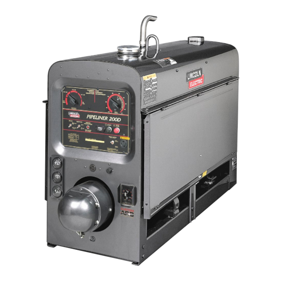
- Page 23 MAINTENANCE 1. Case Front Assembly 2. Engine Assembly 3. Exciter Frame, Armature Assembly 4. Generator Frame, Armature & Coupling 5. Fuel Tank Assembly 6. Generator & Exciter Brush Holder Assemblies 7. Base & Lift Bale Assembly 8. Radiator Assembly 9. Roof & Doors Figure D.2 - Major Component Location PIPELINER®...
- Page 24 NOTES PIPELINER® 200D KUBOTA...
- Page 25 TABLE OF CONTENTS - INSTALLATION SECTION AA-1 AA-1 Installation ................AA-1 Technical Specifications .
- Page 26 INSTALLATION AA-2 AA-2 TECHNICAL SPECIFICATIONS - Pipeliner® 200D (K6090-9) INPUT - DIESEL ENGINE Make/Model Description Horsepower Operating Displacement cu. in.(ltrs) Starting Capacities System PEED 12VDC Battery and starter 4 Cylinder Fuel: 15gal.(57L) High 4 Stroke 28.2 HP Oil: 8.7 qts. 1600RPM Naturally Perkins...
- Page 27 INSTALLATION AA-3 AA-3 SAFETY PRECAUTIONS CAUTION WARNING DO NOT MOUNT OVER COMBUSTIBLE SUR- FACES. Do not attempt to use this equipment until you Where there is a combustible surface directly under have thoroughly read the engine manufacturerʼs manual supplied with your welder. It includes stationary or fixed electrical equipment, the surface important safety precautions, detailed engine shall be covered with a steel plate at least .06”(1.6mm)
- Page 28 INSTALLATION AA-4 AA-4 TRAILERS ( POLARITY CONTROL AND CABLE SIZES See ACCESSORIES SECTION) If the user adapts a non-Lincoln trailer, he must With the engine off, route the electrode and work assume responsibility that the method of attachment cables through the strain relief bracket on the base and and usage does not result in a safety hazard, nor dam- connect to the studs located below the fuel tank mount- age the welding equipment.
- Page 29 INSTALLATION AA-5 AA-5 BATTERY CHARGING WARNING This unit is supplied from the factory with the engine crankcase filled with a high quality SAE 10W/30 oil. GASES FROM BATTERY can explode. This oil should be acceptable for most typical ambient • Keep sparks, flame and cigarettes temperatures.
- Page 30 NOTES AA-6 AA-6 PIPELINER® 200D PERKINS...
- Page 31 TABLE OF CONTENTS - OPERATION SECTION BB-1 BB-1 Operation ................BB-1 Safety Precautions &...
- Page 32 OPERATION BB-2 BB-2 SAFETY PRECAUTIONS The Pipeliner® 200D has a current range of 40-300 DC amps with output ratings as follows: WARNING RATED OUTPUT DUTY CYCLE Do not attempt to use this equipment until you have thoroughly read the engine manufacturerʼs 200A @ 28V manual supplied with your welder.
- Page 33 OPERATION BB-3 BB-3 COLD WEATHER STARTING Cranking System A 12V electric starter is standard. With a fully charged battery and a proper weight oil, the engine should start satisfactorily even down to about - Air Cleaner 15°F -(26°C). If the engine must be frequently started Heavy duty two-stage dry type at or below -15°F -(26°C), it may be desirable to install cold-starting aides.
- Page 34 BB-4 WELDER OPERATION ENGINE BREAK-IN WARNING Lincoln Electric selects high quality, heavy-duty indus- trial engines for the portable welding machines we ELECTRIC SHOCK can kill. offer. While it is normal to see a small amount of • Do not touch electrically live parts or crankcase oil consumption during initial operation, electrode with skin or wet clothing.
- Page 35 OPERATION BB-5 BB-5 When a forceful “digging” arc is required, usually for vertical and overhead welding, use a higher “Current Range Selector” setting and lower open circuit voltage. For example: to obtain 175 amps and a forceful arc, set the “Current Range Selector” to the 240-160 position and the “Fine Current Adjustment”...
- Page 36 NOTES BB-6 BB-6 PIPELINER® 200D PERKINS...
- Page 37 TABLE OF CONTENTS - ACCESSORIES SECTION CC-1 CC-1 Accessories ................CC-1 Optional Features .
- Page 38 The use of an arc welder for pipe thawing is not approved by the CSA, nor is it recommended or supported by Lincoln Electric. ------------------------------------------------------------------------ PIPELINER® 200D PERKINS...
- Page 39 TABLE OF CONTENTS - MAINTENANCE SECTION DD-1 DD-1 Maintenance ................DD-1 Safety Precautions .
- Page 40 MAINTENANCE DD-2 DD-2 SAFETY PRECAUTIONS 4. When necessary, remove the sediment bowl from beneath the gas tank and clean out any accumulat- WARNING ed dirt and water. Replace the fuel filter in the fuel line as needed. Have qualified personnel do the maintenance work.
- Page 41 MAINTENANCE DD-3 DD-3 IDLER MAINTENANCE BEARINGS CAUTION This welder is equipped with a double-shielded ball Before doing electrical work on the idler printed bearing having sufficient grease to last indefinitely circuit board, disconnect the battery. under normal service. Where the welder is used con- ------------------------------------------------------------------------ stantly or in excessively dirty locations, it may be nec- essary to add one-half ounce of grease per year.
- Page 42 MAINTENANCE DD-4 DD-4 1. Loosen by two or three turns, the vent screw 2. Operate the electric fuel pump by turning the (Figure DD.1) on the fuel inlet connection. “Ignition” switch “ON” until fuel, free of air, flows from the vent point. Tighten the vent screw. 3.
- Page 43 MAINTENANCE DD-5 DD-5 1. Case Front Assembly 2. Engine Assembly 3. Exciter Frame, Armature Assembly 4. Generator Frame, Armature & Coupling 5. Fuel Tank Assembly 6. Generator & Exciter Brush Holder Assemblies 7. Base & Lift Bale Assembly 8. Idler Solenoid Assembly 9.
- Page 44 NOTES DD-6 DD-6 PIPELINER® 200D PERKINS...
- Page 45 TABLE OF CONTENTS - INSTALLATION SECTION AAA-1 AAA-1 Installation ................AAA-1 Technical Specifications .
- Page 46 INSTALLATION AAA-2 AAA-2 TECHNICAL SPECIFICATIONS - Pipeliner® 200G (K6090-7) INPUT - GASOLINE ENGINE Make/Model Description Speed (RPM) Displacement Ignition Capacities cu. in. (Ltrs.) System High Idle 1600 Delco Voyager Fuel: 15gal.(57L) 4 Cylinder High Energy 4 Cycle Oil: 4.5Qts.(4.3L) 3.0 Liter Full Load 1600 Distributor Type Pipeliner®...
- Page 47 INSTALLATION AAA-3 AAA-3 SAFETY PRECAUTIONS LOCATION / VENTILATION Always operate the welder with the doors closed. WARNING Leaving the doors open changes the designed air flow and may cause overheating. Do not attempt to use this equipment until you have thoroughly read the engine manufacturerʼs The welder should be located to provide an unrestrict- manual supplied with your welder.
- Page 48 INSTALLATION AAA-4 AAA-4 ANGLE OF OPERATION 5. Conformance with federal, state, and local laws. Consult applicable federal, state, and local laws To achieve optimum engine performance the regarding specific requirements for use on pub- Pipeliner® 200G should be run in a level position. The lic highways.
- Page 49 INSTALLATION AAA-5 AAA-5 PRE-OPERATION SERVICE WARNING CAUTION GASES FROM BATTERY can explode. • Keep sparks, flame and cigarettes READ the engine operating and maintenance instruc- away. tions supplied with this machine. ------------------------------------------------------------------------ WARNING BATTERY ACID can burn eyes and skin. •...
- Page 50 NOTES AAA-6 AAA-6 PIPELINER® 200G...
- Page 51 TABLE OF CONTENTS - OPERATION SECTION BBB-1 BBB-1 Operation ................BBB-1 Safety Precautions &...
- Page 52 OPERATION BBB-2 BBB-2 SAFETY PRECAUTIONS DESIGN SUMMARY WARNING Control Panel Do not attempt to use this equipment until you have thoroughly read the engine manufacturerʼs Both the engine and the welder controls are located on manual supplied with your welder. It includes one recessed panel at the exciter end of the machine.
- Page 53 OPERATION BBB-3 BBB-3 STOPPING THE ENGINE Cranking System A 12V electric starter is standard. • Turn the Ignition switch to “OFF”. Air Cleaner At the end of each dayʼs welding, refill the fuel tank to minimize moisture condensation in the tank. Also, run- Heavy duty two-stage dry type ning out of fuel tends to draw dirt into the fuel system.
- Page 54 OPERATION BBB-4 BBB-4 CONTROL OF WELDING CURRENT IDLER OPERATION The operating speeds are as follows: CAUTION ORDERING ENGINE FULL HIGH DO NOT TURN THE “CURRENT RANGE SELEC- INFO. LOAD IDLE IDLE TOR” WHILE WELDING because the current may arc between the contacts and damage the switch. K6090-7 GM 3.0L 1600-...
- Page 55 TABLE OF CONTENTS - ACCESSORIES SECTION CCC-1 CCC-1 Accessories ............... . .CCC-1 Optional Equipment &...
- Page 56 The use of an arc welder Innershield welding. Also, excellent for MIG welding. for pipe thawing is not approved by the CSA, nor is Easy Installation. Recommended wire feeder is the it recommended or supported by Lincoln Electric. LN-25. ------------------------------------------------------------------------ (K924-4) REMOTE CONTROL...
- Page 57 TABLE OF CONTENTS - MAINTENANCE SECTION DDD-1 DDD-1 Maintenance ............... . .DDD-1 Safety Precautions .
- Page 58 MAINTENANCE DDD-2 DDD-2 SAFETY PRECAUTIONS 3. Change the crankcase oil and oil filter after the first 50 hours of operation and thereafter at regular WARNING intervals using the proper grade of oil. See the rec- ommendations in the engine operation manual. Have qualified personnel do the maintenance work.
- Page 59 MAINTENANCE DDD-3 DDD-3 BEARINGS IDLE CONTROL MAINTENANCE CAUTION This welder is equipped with a double-shielded ball bearing having sufficient grease to last indefinitely Before doing electrical work on the idler printed under normal service. Where the welder is used con- circuit board, disconnect the battery.
- Page 60 MAINTENANCE DDD-4 DDD-4 ENGINE SERVICE EVERY DAY OR EVERY 8 HOURS FIRST SERVICE-(50 HOURS) EVERY 100 HOURS OR 3 MONTHS EVERY 200 HOURS OR 6 MONTHS EVERY 600 HOURS OR 12 MONTHS ENGINE SERVICE (NOTE 2) MAINTENANCE ITEM TYPE OR QUANTITY Coolant level Concentration of antifreeze 50 / 50 water glycol mixture...
- Page 61 MAINTENANCE DDD-5 DDD-5 1. Case Front Assembly 2. Engine Assembly 3. Exciter Frame, Armature Assembly 4. Generator Frame, Armature & Coupling 5. Fuel Tank Assembly 6. Generator & Exciter Brush Holder Assemblies 7. Base & Lift Bale Assembly 8. Radiator Assembly 9.
- Page 62 NOTES DDD-6 DDD-6 PIPELINER® 200G...
- Page 63 TABLE OF CONTENTS-THEORY OF OPERATION SECTION Theory of Operation ..............E-1 General Description .
- Page 64 THEORY OF OPERATION FIGURE E.2 — GENERAL DESCRIPTION ENGINE ENGINE FROM CURRENT FAILURE HOUR LAMP SENSING P.C. BOARD METER ENGINE CONTROL/PROTECTION MODULE SELECTOR ENGINE SWITCH FROM CURRENT ENGINE PROTECTION HOUR SENSING P.C. BOARD LAMP IDLER 90 Min. ENGINE FROM CURRENT IGNITION METER FAILURE...
- Page 65 THEORY OF OPERATION FIGURE E.3 — ENGINE CONTROL ENGINE FROM CURRENT ENGINE PROTECTION HOUR LAMP SENSING P.C. BOARD METER IDLER SWITCH ENGINE CONTROL UNIT (ECU) CONTROL GAUGE TEMP. GAUGE ENGINE ENGINE TEMP. SPEED SPEED SENSOR ACTUATOR SENSOR SWITCH SENSOR SWITCH STARTER MOTOR KUBOTA...
- Page 66 THEORY OF OPERATION FIGURE E.4 — ENGINE CONTROL ENGINE ENGINE FROM CURRENT FAILURE HOUR LAMP SENSING P.C. BOARD METER IDLER IGNITION IDLER/ENGINE SWITCH SWITCH PROTECTION P.C. BOARD BATTERY TEMP. GAUGE GAUGE FUEL PUMP FUEL SOLENOID TEMP. SENSOR SWITCH SENSOR STARTER SWITCH ENGINE MOTOR...
- Page 67 THEORY OF OPERATION FIGURE E.5 — ENGINE CONTROL ENGINE FROM CURRENT ENGINE FAILURE HOUR SENSING P.C. BOARD LAMP METER IDLER SWITCH ZENITH THROTTLE FUEL INJECTORS BODY CONTROLLER FUEL CONTROL PUMP THROTTLE PLATE MOTOR ENG. IGNITION WATER GAUGE CIRCUITRY GAUGE WATER &...
- Page 68 THEORY OF OPERATION FIGURE E.6 — GENERATOR & EXCITER ENGINE CONTROL/PROTECTION MODULE SELECTOR SWITCH 90 Min. NEGATIVE OUTPUT Current TERMINAL Sensing P.C. Board SERIES RESIDUAL COILS MAGNETISM SHUNT FIELD GENERATOR MECHANICAL ARMATURE EXCITER COUPLING ARMATURE SHAFT ARMATURE 15 AMP SERIES FUSE FIELD SHUNT...
- Page 69 THEORY OF OPERATION FIGURE E.7 — DC GENERATOR THEORY SHUNT FIELD WINDINGS DC CURRENT MAGNETIC FIELD BRUSH GENERATOR MECHANICAL ARMATURE SHAFT COUPLING ARMATURE BRUSH MAGNETIC FIELD DC CURRENT SHUNT FIELD WINDINGS DC GENERATOR MACHINES The armature winding of a DC generator is located on the rotating member.
- Page 70 NOTES PIPELINER® 200...
- Page 71 TABLE OF CONTENTS - TROUBLESHOOTING & REPAIR Troubleshooting and Repair ............. .F-1 How to Use Troubleshooting Guide .
-
Page 72: Troubleshooting And Repair
HOW TO USE TROUBLESHOOTING GUIDE WARNING Service and Repair should only be performed by Lincoln Electric Factory Trained Personnel. Unauthorized repairs performed on this equipment may result in danger to the technician and machine operator and will invalidate your factory warranty. For your safety and to avoid Electrical Shock, please observe all safety notes and precautions detailed throughout this manual. -
Page 73: Pc Board Troubleshooting Procedures
Do not touch electrically hot parts. - If you return a PC board to The Lincoln Electric Company for credit, it must be in the static-shielding bag. This will prevent further damage and allow prop- CAUTION er failure analysis. - Page 74 Check for grounds and/or shorts. CAUTION If for any reason you do not understand the test procedures or are unable to perform the tests/repairs safely, contact the Lincoln Electric Service Department for technical troubleshooting assistance before you proceed. Call 1-888-935-3877. PIPELINER® 200...
- Page 75 GM 3.0L gas) correctly. CAUTION If for any reason you do not understand the test procedures or are unable to perform the tests/repairs safely, contact the Lincoln Electric Service Department for technical troubleshooting assistance before you proceed. Call 1-888-935-3877. PIPELINER® 200...
- Page 76 3. Perform the DC Exciter Test. CAUTION If for any reason you do not understand the test procedures or are unable to perform the tests/repairs safely, contact the Lincoln Electric Service Department for technical troubleshooting assistance before you proceed. Call 1-888-935-3877. PIPELINER® 200...
- Page 77 Service Dept. 1-888-935- 3877. CAUTION If for any reason you do not understand the test procedures or are unable to perform the tests/repairs safely, contact the Lincoln Electric Service Department for technical troubleshooting assistance before you proceed. Call 1-888-935-3877. PIPELINER® 200...
- Page 78 Service Dept. 1-888-935- 3877. CAUTION If for any reason you do not understand the test procedures or are unable to perform the tests/repairs safely, contact the Lincoln Electric Service Department for technical troubleshooting assistance before you proceed. Call 1-888-935-3877. PIPELINER® 200...
- Page 79 Lincoln Electric Service Dept. 1-888-935-3877. CAUTION If for any reason you do not understand the test procedures or are unable to perform the tests/repairs safely, contact the Lincoln Electric Service Department for technical troubleshooting assistance before you proceed. Call 1-888-935-3877. PIPELINER® 200...
- Page 80 Lincoln Electric Service Dept. at 1-888-935-3877. CAUTION If for any reason you do not understand the test procedures or are unable to perform the tests/repairs safely, contact the Lincoln Electric Service Department for technical troubleshooting assistance before you proceed. Call 1-888-935-3877. PIPELINER® 200...
- Page 81 TROUBLESHOOTING & REPAIR F-11 F-11 Observe all Safety Guidelines detailed throughout this manual Kubota - EUC - Codes LIGHT CODE FAILURE DETECTED POSSIBLE CAUSE - CORRECTIVE MEASURE LONG 1, SHORT 1 RPM IS OVER 115% OF RATED RPM (2070 RPM) ACTUATOR IS STUCK - REMOVE ACTUATOR AND VERIFY PLUNGER PULLS IN WHEN ENERGIZED LONG 1, SHORT 2...
- Page 82 NOTES F-12 F-12 PIPELINER® 200...
-
Page 83: Dc Exciter Test
DC EXCITER TEST WARNING Service and repair should be performed by only Lincoln Electric factory trained personnel. Unauthorized repairs performed on this equipment may result in danger to the technician or machine operator and will invalidate your factory warranty. For your safety and to avoid electrical shock, please observe all safety notes and precautions detailed throughout this manual. - Page 84 TROUBLESHOOTING & REPAIR F-14 F-14 DC EXCITER TEST (CONTINUED) FIGURE F.1 – 120VDC RECEPTACLE SERIES COIL CONNECTION POINT (NEGATIVE) POSITIVE TEST PROCEDURE 2. Start the engine and put the idler switch in the HIGH 1. Turn off the engine and remove all external loads idle position.
- Page 85 TROUBLESHOOTING & REPAIR F-15 F-15 DC EXCITER TEST (CONTINUED) FIGURE F.2 – EXCITER COVER REMOVAL WARRANTY CHECK VOLTAGE EXITER AT BRUSH COVER HOLDERS HERE (RIGHT SIDE IS +) 4. Turn off the engine. Using the 3/8” nut driver, remove the exciter cover. See Figure F.2. 5.
- Page 86 TROUBLESHOOTING & REPAIR F-16 F-16 DC EXCITER TEST (continued) FIGURE F.3 – BRUSH HOLDER LEADS WARRANTY WHITE FLEX RED LEAD - LEAD EXCITER ARMATURE 120 VOLTS EXCITER SERIES FIELD EXCITER SHUNT FIELD SMALL FLEX LEAD SOLID LEAD SHUNT COIL AND SERIES COIL RESISTANCE TESTS 12.
-
Page 87: Idler Solenoid Test
IDLER SOLENOID TEST WARNING Service and repair should be performed by only Lincoln Electric factory trained personnel. Unauthorized repairs performed on this equipment may result in danger to the technician or machine operator and will invalidate your factory warranty. For your safety and to avoid electrical shock, please observe all safety notes and precautions detailed throughout this manual. - Page 88 TROUBLESHOOTING & REPAIR F-18 F-18 IDLER SOLENOID TEST (continued) FIGURE F.4 – IDLER SOLENOID CONNECTIONS QUICK CONNECT LEADS TEST PROCEDURE 7. If the solenoid does not operate properly, check for 1. Turn the engine OFF. a mechanical restriction in the linkage or for a miss- 2.
- Page 89 MAIN GENERATOR SHUNT FIELD WINDING TEST WARNING Service and repair should be performed by only Lincoln Electric factory trained personnel. Unauthorized repairs performed on this equipment may result in danger to the technician or machine operator and will invalidate your factory warranty. For your safety and to avoid electrical shock, please observe all safety notes and precautions detailed throughout this manual.
- Page 90 TROUBLESHOOTING & REPAIR F-20 F-20 MAIN GENERATOR SHUNT FIELD WINDING TEST (continued) FIGURE F.5 – PLUG P10 LOCATION PLUG P10 TEST PROCEDURE 1. Turn the engine OFF. 2. Unlatch, lift and secure the right side door. 3. Locate plug P10. See Figure F.5. 4.
- Page 91 TROUBLESHOOTING & REPAIR F-21 F-21 MAIN GENERATOR SHUNT FIELD WINDING TEST (continued) FIGURE F.6 – PLUG P10 PIN ASSIGNMENTS PIN 3 PIN 5 5. Locate the blue (U) (pin 3) and the brown (N) 9. If the plug and associated leads are okay, (pin 5) leads in the harness plug.
- Page 92 NOTES F-22 F-22 PIPELINER® 200...
-
Page 93: Flashing The Fields
FLASHING THE FIELDS WARNING Service and repair should be performed by only Lincoln Electric factory trained personnel. Unauthorized repairs performed on this equipment may result in danger to the technician or machine operator and will invalidate your factory warranty. For your safety and to avoid electrical shock, please observe all safety notes and precautions detailed throughout this manual. - Page 94 TROUBLESHOOTING & REPAIR F-24 F-24 FLASHING THE FIELDS (continued) FIGURE F.7 – EXCITER COVER REMOVAL EXITER COVER PROCEDURE 1. Turn the engine OFF. 2. Using a 3/8” Nutdriver, remove the exciter cover. See Figure F.7. PIPELINER® 200...
- Page 95 TROUBLESHOOTING & REPAIR F-25 F-25 FLASHING THE FIELDS (continued) FIGURE F.8 - BRUSH HOLDER/BATTERY JUMPER CONNECTIONS WARRANTY RAISE EXCITER BRUSH OFF COMMUTATOR TO NEGATIVE TO POSITIVE BATTERY BATTERY TERMINAL TERMINAL 3. Raise one exciter brush off the armature commuta- 6. Remove both leads from the brush holders and the tor.
- Page 96 NOTES F-26 F-26 PIPELINER® 200...
-
Page 97: Engine Alternator Test
ENGINE ALTERNATOR TEST WARNING Service and repair should be performed by only Lincoln Electric factory trained personnel. Unauthorized repairs performed on this equipment may result in danger to the technician or machine operator and will invalidate your factory warranty. For your safety and to avoid electrical shock, please observe all safety notes and precautions detailed throughout this manual. - Page 98 TROUBLESHOOTING & REPAIR F-28 F-28 ENGINE ALTERNATOR TEST (CONTINUED) FIGURE F.9 - ALTERNATOR LEAD LOCATIONS BACK OF ALTERNATOR Alternator Output Leads TEST PROCEDURE 1. Turn the engine off. 8. Make sure the idle switch is still in the “high” position, start the engine, and allow it to run at 2.
- Page 99 OIL PRESSURE - TEMPERATURE SWITCH TEST WARNING Service and repair should be performed by only Lincoln Electric factory trained personnel. Unauthorized repairs performed on this equipment may result in danger to the technician or machine operator and will invalidate your factory warranty. For your safety and to avoid electrical shock, please observe all safety notes and precautions detailed throughout this manual.
- Page 100 TROUBLESHOOTING & REPAIR F-30 F-30 OIL PRESSURE - TEMPERATURE SWITCH TEST (CONTINUED) FIGURE F.10 - SWITCH TEMP SW. / SENDER S25162 1/2-14 NPT 1/4" SPADE TERMINAL OIL SWITCH / SENDER .19 .03 3/16" SPADE TERMINAL S17026-3 WK TERMINAL TO GROUND TO CASE AT 6 +/-2 PSI. OTHERWISE TERMINAL TO BE OPEN Oil Pressure Switch/Sender Resistance Test.
- Page 101 TROUBLESHOOTING & REPAIR F-31 F-31 OIL PRESSURE - TEMPERATURE SWITCH TEST (CONTINUED) Temperature Switch/Sender Resistance Test. S25162 (Kubota and Perkins Only) PROCEDURE 1. With the engine not running, and at room 6. With engine running the resistance from termi- temperature, locate the Temperature nal G to case ground should be as follows.
- Page 102 NOTES F-32 F-32 PIPELINER® 200...
-
Page 103: Current Sensor Pcb Test
CURRENT SENSOR PCB TEST WARNING Service and repair should be performed by only Lincoln Electric factory trained personnel. Unauthorized repairs performed on this equipment may result in danger to the technician or machine operator and will invalidate your factory warranty. For your safety and to avoid electrical shock, please observe all safety notes and precautions detailed throughout this manual. - Page 104 TROUBLESHOOTING & REPAIR F-34 F-34 CURRENT SENSOR PCB TEST (CONTINUED) FIGURE F.11 - CASE COVERS BOLT / NUT (4) “L” DOOR HOOKS (4) PROCEDURE 6. Turn the engine on and record the voltage 1. Turn the engine off. between pins 4 and 2 on J1. The Idler Switch 2.
- Page 105 TROUBLESHOOTING & REPAIR F-35 F-35 CURRENT SENSOR PCB TEST (CONTINUED) FIGURE F.12 - CURRENT SENSING PCB PIPELINER® 200...
- Page 106 NOTES F-36 F-36 PIPELINER® 200...
-
Page 107: Engine Throttle Adjustment Test (Perkins Only
(PERKINS ONLY) WARNING Service and repair should be performed by only Lincoln Electric factory trained personnel. Unauthorized repairs performed on this equipment may result in danger to the technician or machine operator and will invalidate your factory warranty. For your safety and to avoid electrical shock, please observe all safety notes and precautions detailed throughout this manual. - Page 108 TROUBLESHOOTING & REPAIR F-38 F-38 ENGINE THROTTLE ADJUSTMENT TEST (CONTINUED) (PERKINS ONLY) FIGURE F.13 - BLOWER PADDLE MARK LOCATION BLOWER PADDLE MARK PROCEDURE Strobe Tach Method 1. Turn the engine off. 5. Start the engine and direct the strobe-tach light on the blower paddle.
- Page 109 TROUBLESHOOTING & REPAIR F-39 F-39 ENGINE THROTTLE ADJUSTMENT TEST (CONTINUED) (PERKINS ONLY) PROCEDURE 6. If either of the readings is incorrect, adjust the throt- tle as follows: Adjust HIGH IDLE: The Engine is Preset at factory. Contact Perkins @ 1-888-737-5364 or www.perkins.com Adjust LOW IDLE: First make sure there is no load on the machine.
- Page 110 TROUBLESHOOTING & REPAIR F-40 F-40 ENGINE THROTTLE ADJUSTMENT TEST (CONTINUED) (PERKINS ONLY) FIGURE F.14 – SOLENOID LOCATION IDLER ADJUSTMENT LOCK NUT BALL JOINT IDLER ROD PIPELINER® 200...
- Page 111 TROUBLESHOOTING & REPAIR F-41 F-41 NORMAL OPEN CIRCUIT VOLTAGE WAVEFORM (115VDC SUPPLY) HIGH IDLE – NO LOAD – FINE CURRENT CONTROL RHEOSTAT AT MAXIMUM 0 volts 2 ms 50 volts This is the typical auxiliary output voltage generated from a properly operating machine.
- Page 112 TROUBLESHOOTING & REPAIR F-42 F-42 NORMAL OPEN CIRCUIT DC WELD VOLTAGE WAVEFORM HIGH IDLE – NO LOAD – FINE CURRENT CONTROL RHEOSTAT AND SELECTOR SWITCH AT MAXIMUM 0 volts 50 volts 5 ms This is the typical DC welding output voltage generated from a properly operating machine.
- Page 113 TROUBLESHOOTING & REPAIR F-43 F-43 TYPICAL DC WELD VOLTAGE WAVEFORM MACHINE LOADED – SELECTOR SWITCH AT MAXIMUM 0 volts 5 ms 20 volts MACHINE LOADED TO 200 AMPS AT 40VDC This is the typical DC welding output voltage generated from a properly operating machine.
- Page 114 NOTES F-44 F-44 PIPELINER® 200...
- Page 115 REMOVAL AND REPLACEMENT PROCEDURE WARNING Service and repair should be performed by only Lincoln Electric factory trained personnel. Unauthorized repairs performed on this equipment may result in danger to the technician or machine operator and will invalidate your factory warranty. For your safety and to avoid electrical shock, please observe all safety notes and precautions detailed throughout this manual.
- Page 116 TROUBLESHOOTING & REPAIR F-46 F-46 DC EXCITER ARMATURE & FIELD COILS REMOVAL AND REPLACEMENT PROCEDURE FIGURE F.15 – EXCITER COVER REMOVAL POLE PIECE BOLTS (4) EXITER FRAME BRUSH HOLDER ARMATURE ASSEMBLY (2) SLEEVE COLLAR FLAT WASHER ARMATURE LOCKING NUT EXITER COVER PROCEDURE Reassembly: DC Exciter Armature Removal Procedure...
- Page 117 TROUBLESHOOTING & REPAIR F-47 F-47 DC EXCITER ARMATURE & FIELD COILS REMOVAL AND REPLACEMENT PROCEDURE Field Coils Removal Procedure Reassembly: 1. Perform the DC Exciter Armature Removal 7. Assemble the new coils to their respective Procedure. pole pieces. 2. Using the 3/8” wrench, remove the leads from 8.
- Page 118 NOTES F-48 F-48 PIPELINER® 200...
- Page 119 MAIN GENERATOR FRAME REMOVAL AND REPLACEMENT PROCEDURE WARNING Service and repair should be performed by only Lincoln Electric factory trained personnel. Unauthorized repairs performed on this equipment may result in danger to the technician or machine operator and will invalidate your factory warranty. For your safety and to avoid electrical shock, please observe all safety notes and precautions detailed throughout this manual.
- Page 120 TROUBLESHOOTING & REPAIR F-50 F-50 MAIN GENERATOR FRAME REMOVAL AND REPLACEMENT PROCEDURE (CONTINUED) FIGURE F.16 – BATTERY PANEL REMOVAL NEGATIVE BATTERY CABLE PROCEDURE 3. Using the 1/2” wrench, remove the negative 1. Turn the engine OFF. battery cable. 2. Using the 7/16” wrench, remove the two bolts and washers and partially slide out the battery mounting panel.
- Page 121 TROUBLESHOOTING & REPAIR F-51 F-51 MAIN GENERATOR FRAME REMOVAL AND REPLACEMENT PROCEDURE (CONTINUED) FIGURE F.17 – TOP AND DOORS ASSEMBLY DETAILS BOLT / NUT (4) 'L' DOOR HOOKS (4) 4. Using the 1/2” wrench, remove the four nuts and bolts holding the case top and doors assembly to the welder frame.
- Page 122 TROUBLESHOOTING & REPAIR F-52 F-52 MAIN GENERATOR FRAME REMOVAL AND REPLACEMENT PROCEDURE (CONTINUED) FIGURE F.18 – FUEL TANK MOUNTING DETAILS BOLTS / NUTS / WASHERS (4) FUEL LINE FUEL TANK FUEL BOWL RAILS 5. Perform the DC Exciter Armature Removal 7.
- Page 123 TROUBLESHOOTING & REPAIR F-53 F-53 MAIN GENERATOR FRAME REMOVAL AND REPLACEMENT PROCEDURE (CONTINUED) FIGURE F.19 – SELECTOR SWITCH LEAD REMOVAL SELECTOR SWITCH TERMINAL LEAD (5) 9. Using the 1/2” wrench, remove the five heavy flex leads from the selector switch terminals. Label the leads for reassembly.
- Page 124 TROUBLESHOOTING & REPAIR F-54 F-54 MAIN GENERATOR FRAME REMOVAL AND REPLACEMENT PROCEDURE (CONTINUED) FIGURE F.21 – CHOKE CONTROL CABLE REMOVAL LOOSEN CHOKE HERE CABLE 12. Using the slot head screw driver, remove the choke control cable from the engine carbure- tor assembly.
- Page 125 TROUBLESHOOTING & REPAIR F-55 F-55 MAIN GENERATOR FRAME REMOVAL AND REPLACEMENT PROCEDURE (CONTINUED) FIGURE F.22 – FRONT PANEL WIRING CONNECTIONS IDLER PC BOARD IDLER SWITCH TO IDLER SWITCH IGNITION SWITCH LEADS TO AMMETER START BUTTON SHUNT LEADS DC RECEPTACLE QUICK DISCONNECT 13.
- Page 126 TROUBLESHOOTING & REPAIR F-56 F-56 MAIN GENERATOR FRAME REMOVAL AND REPLACEMENT PROCEDURE (CONTINUED) FIGURE F.23 – FRONT PANEL FASTENER REMOVAL BOLTS / NUTS / WASHERS (2) MIDDLE SCREW (1) BASE MOUNTING BOLTS (4) 23. Using the 1/2” wrench, remove the two bolts, 25.
- Page 127 TROUBLESHOOTING & REPAIR F-57 F-57 MAIN GENERATOR FRAME REMOVAL AND REPLACEMENT PROCEDURE (CONTINUED) FIGURE F.24 – BRUSH BRACKET WRAP-AROUND COVER BRUSH BRACKET REMOVE (2) NUTS, WASHERS, AND SCREWS WRAP- AROUND COVER 27. Using the slot head screw driver, remove the two screws and nuts from the brush bracket wrap-around cover.
- Page 128 TROUBLESHOOTING & REPAIR F-58 F-58 MAIN GENERATOR FRAME REMOVAL AND REPLACEMENT PROCEDURE (CONTINUED) FIGURE F.26 – MAIN GENERATOR FEET MOUNTING MAIN GENERATOR FEET (2) REMOVE MOUNTING NUTS, WASHERS, AND BOL TS 30. Using the 3/4” wrench, remove the frame mounting bolts, nuts, and washers from the feet of the main generator.
- Page 129 TROUBLESHOOTING & REPAIR F-59 F-59 MAIN GENERATOR FRAME REMOVAL AND REPLACEMENT PROCEDURE (CONTINUED) 33. Using the rope sling and pry bars, carefully 8. Carefully position the fuel tank to the mount- lift and “wiggle” the generator frame away ing rails. Using the 9/16” wrench, install the from the engine and armature assembly.
- Page 130 NOTES F-60 F-60 PIPELINER® 200...
- Page 131 REMOVAL AND REPLACEMENT PROCEDURE WARNING Service and repair should be performed by only Lincoln Electric factory trained personnel. Unauthorized repairs performed on this equipment may result in danger to the technician or machine operator and will invalidate your factory warranty. For your safety and to avoid electrical shock, please observe all safety notes and precautions detailed throughout this manual.
- Page 132 TROUBLESHOOTING & REPAIR F-62 F-62 MAIN GENERATOR ARMATURE REMOVAL AND REPLACEMENT PROCEDURE FIGURE F.28 – MAIN GENERATOR ARMATURE MOUNTING SLING BLOWER PADDLE MOUNTING BOLTS / LOCK WASHERS (8) PROCEDURE Replacement: Refer to Figure F.28 1. Turn the engine OFF. 1. Support the armature with the rope sling. 2.
- Page 133 TROUBLESHOOTING & REPAIR F-63 F-63 RETEST AFTER REPAIR Retest a machine: • If it is rejected under test for any reason that requires you to remove any mechanical part which could affect the machineʼs electrical characteristics. • If you repair or replace any electrical components. ENGINE OUTPUT Engine Mode...
- Page 134 NOTES F-64 F-64 PIPELINER 200...
- Page 135 Schematic – Idler / Engine Shutdown - Code 10929 - (L10826) ....... .G-11 * NOTE: Many PC Board Assemblies are now totally encapsulated, surface mounted and or multi-lay- ered and are therefore considered to be unserviceable. Assembly drawings of these boards are no longer provided. PIPELINER 200...
-
Page 136: Electrical Diagrams
ELECTRICAL DIAGRAMS WIRING DIAGRAM - CODE 10660 - (L11402) PIPELINER 200G WIRING DIAGRAM ELECTRICAL SYMBOLS PER E1537 ZENITH THROTTLE RPM CONTROL BODY 10 K LEAD COLOR CODE CONTROLLER INJECTOR WHITE B - BLACK CONTROL PANEL COMPONENTS CONNECTOR G - GREEN SHOWN AS VIEWED FROM REAR. -
Page 137: Wiring Diagram - Code 10913, 11136 - (L11864
ELECTRICAL DIAGRAMS WIRING DIAGRAM - CODE 10913, 11136 - (L11864) PIPELINER 200G WIRING DIAGRAM ELECTRICAL SYMBOLS CONTROL PANEL COMPONENTS PER E1537 ZENITH THROTTLE RPM CONTROL SHOWN AS VIEWED FROM REAR. LEAD COLOR CODE BODY 10 K NEUTRAL BONDED TO FRAME CONTROLLER B - BLACK OR U - BLUE... -
Page 138: Wiring Diagram - Code 10929 - (M20056
ELECTRICAL DIAGRAMS WIRING DIAGRAM - CODE 10929 - (M20056) PIPELINER 200D WIRING DIAGRAM ELECTRICAL SYMBOLS PER E1537 LEAD COLOR CODE CONTROL PANEL COMPONENTS B-BLACK OR R-RED OR GLOW PLUGS SHOWN AS VIEWED FROM REAR. GRAY PINK EXCITER BRUSHES SHOWN AS G-GREEN U-BLUE VIEWED FROM CONTROL PANEL... -
Page 139: Wiring Diagram - Code 11114, 11316 - (M20464
ELECTRICAL DIAGRAMS WIRING DIAGRAM - CODE 11114, 11316 - (M20464) PIPELINER 200D WIRING DIAGRAM ENGINE CONTROL UNIT CONNECTOR DETAIL CONTROL PANEL COMPONENTS SHOWN AS VIEWED FROM REAR. LEAD COLOR CODE LEADS CONNECTED TO ENGINE CONTROL UNIT, SEE DETAIL B-BLACK OR R-RED OR GRAY PINK... -
Page 140: Wiring Diagram - Code 11471 - (M21564
ELECTRICAL DIAGRAMS WIRING DIAGRAM - CODE 11471 - (M21564) PIPELINER 200D WIRING DIAGRAM ENGINE CONTROL UNIT CONNECTOR DETAIL CONTROL PANEL COMPONENTS SHOWN AS VIEWED FROM REAR. LEAD COLOR CODE LEADS CONNECTED TO ENGINE CONTROL UNIT, SEE DETAIL B-BLACK OR R-RED OR GRAY PINK G-GREEN... -
Page 141: Schematic - Complete Machine - Code 10929 - (L12020
ELECTRICAL DIAGRAMS SCHEMATIC -COMPLETE MACHINE - CODE 10929 - (L12020) CHANGE DETAIL: Released A.01 from "X" ENGINEERING CONTROLLED MANUFACTURER: K924-5 REMOTE CONTROL LEFT SIDEOF ENGINE(ASVIEW ED IDLER / ENGINE PROTECTION PC BOARD AMMETER SHOWS FULL (OPTIONAL) FROM CONTROL PANEL) DISCHARGE WHILE PRESSING LOCATED BEHIND UPPER PORTION OF CONTROL PANEL GLOW PLUG ALTERNATOR... -
Page 142: Schematic - Complete Machine - Code 11114. 11316 - (L12362
ELECTRICAL DIAGRAMS SCHEMATIC - COMPLETE MACHINE - CODE 11114, 11316 - (L12362) CHANGE DETAIL: Released A.02 from X ENGINEERING CONTROLLED MANUFACTURER: K924-5 REMOTE CONTROL JUMPER PLUG IS BEHIND LOW ER LOW ER RIGHT OFCONTROL PANEL (OPTIONAL) RIGHTSIDE OFCONTROL PANEL RPM CONTROL POTENTIOMETER AMMETER SHOWS FULL 12 VOLT SUPPLY DISCHARGE WHILE PRESSING... -
Page 143: Schematic - Complete Machine - Code 11471 - (L13350
ELECTRICAL DIAGRAMS SCHEMATIC - COMPLETE MACHINE - CODE 11471 - (L13350) ENGINEERING CONTROLLED CHANGE DETAIL: JUMPER PLUG IS BEHIND LOW ER MANUFACTURER: LOW ER RIGHT OF CONTROL PANEL RIGHT SIDE OF CONTROL PANEL K924-5 REMOTE CONTROL AMMETER SHOWS FULL RPM CONTROL POTENTIOMETER DISCHARGE WHILE PRESSING 12 VOLT SUPPLY GLOW PLUG... -
Page 144: Schematic - Current Sense Pc Board - Code 10929, 11114, 11316, 11471 - (S25973
G-10 G-10 ELECTRICAL DIAGRAMS SCHEMATIC - CURRENT SENSE PC BOARD - CODE 10929,11114, 11316, 11471 - (S25973) ENGINEERING CONTROLLED CHANGE DETAIL: MANUFACTURER: THIS DOCUMENT CONTAINS PROPRIETARY INFORMATION OWNED BY LINCOLN GLOBAL, INC. AND MAY NOT BE DUPLICATED, COMMUNICATED PROPRIETARY & CONFIDENTIAL: TO OTHER PARTIES OR USED FOR ANY PURPOSE WITHOUT THE EXPRESS WRITTEN PERMISSION OF LINCOLN GLOBAL, INC. -
Page 145: Schematic - Idler/Engine Shutdown - Code 10929 (L10826)
G-11 G-11 ELECTRICAL DIAGRAMS SCHEMATIC - IDLER/ENGINE SHUTDOWN - CODE 10929 (L10826) NOTE: This diagram is for reference only. It may not be accurate for all machines covered by this manual. PIPELINER® 200...
Need help?
Do you have a question about the PIPELINER 200 and is the answer not in the manual?
Questions and answers