Table of Contents
Advertisement
For use with machines having Code Numbers:
Safety Depends on You
Lincoln arc welding and cutting
equipment is designed and built
with safety in mind. However,
your overall safety can be
increased by proper installation
... and thoughtful operation on
your part. DO NOT INSTALL,
OPERATE OR REPAIR THIS
EQUIPMENT WITHOUT READ-
ING THIS MANUAL AND THE
SAFETY PRECAUTIONS CON-
TAINED THROUGHOUT. And,
most importantly, think before
you act and be careful.
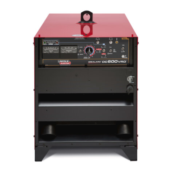
Equipped with VRD (VOLTAGE REDUCTION DEVICE)
See Operation Section for an explanation.
• Sales and Service through Subsidiaries and Distributors Worldwide •
Cleveland, Ohio 44117-1199 U.S.A. TEL: 216.481.8100 FAX: 216.486.1751 WEB SITE: www.lincolnelectric.com
RETURN TO MAIN MENU
IDEALARC
11598, 11613, 11707, 11725
OPERATOR'S MANUAL
• World's Leader in Welding and Cutting Products •
DC-600 VRD
Copyright © Lincoln Global Inc.
IM10018-A
December, 2010
Advertisement
Table of Contents

Related Manuals for Lincoln Electric IDEALARC IM10018-A


Summary of Contents for Lincoln Electric IDEALARC IM10018-A
- Page 1 IDEALARC For use with machines having Code Numbers: Safety Depends on You Lincoln arc welding and cutting equipment is designed and built with safety in mind. However, your overall safety can be increased by proper installation ... and thoughtful operation on your part.
-
Page 2: Electric And Magnetic Fields
351040, Miami, Florida 33135 or CSA Standard W117.2-1974. A Free copy of “Arc Welding Safety” booklet E205 is available from the Lincoln Electric Company, 22801 St. Clair Avenue, Cleveland, Ohio 44117-1199. bE SURE THAT ALL INSTALLATION, OPERATION, MAINTENANCE AND REPAIR PROCEDURES ARE PERFORMED ONLY bY QUALIFIED INDIVIDUALS. - Page 3 SAFETY IDEALARC® DC-600 VRD...
- Page 4 SAFETY IDEALARC® DC-600 VRD...
- Page 5 IDEALARC® DC-600 VRD...
- Page 6 Electric for advice or information about their use of our products. We respond to our customers based on the best information in our posses- sion at that time. Lincoln Electric is not in a position to warrant or guarantee such advice, and assumes no liability, with respect to such infor- mation or advice.
-
Page 7: Table Of Contents
TAbLE OF CONTENTS Installation ...Section A Technical Specifications ... A-1 Safety Precautions ... A-2 Select Proper Location...A-2 Limit on Stacking ...A-2 Stacking ...A-2 Tilting ...A-2 Electrical Input Connections ... A-3 Fuses and Wire Sizes...A-3 Ground Connection ... A-3 Input Power Supply Connections...A-3 Reconnect Procedure ... - Page 8 Maintenance ...Section D Safety Precautions ...D-1 Routine and Periodic Maintenance...D-1 Troubleshooting ...Section E Safety Precautions...E-1 How to Use Troubleshooting Guide...E-1 Troubleshooting Guide ...E-2 Wiring Diagrams, Connection Diagrams and Dimension Prints...Section F Parts List ...P-631 Series TAbLE OF CONTENTS Page...
-
Page 9: Installation
TECHNICAL SPECIFICATIONS – IDEALARC® DC-600 VRD CODES Standard Voltage 11613, 11707 230/460/575/60 415/50/60 11598, 11725 Duty Cycle 100% Duty Cycle 60% Duty Cycle 50% Duty Cycle Output Range 70A/13V-780A/44V (CV) 90A/24V-780A/44V (CC) RECOMMENDED INPUT WIRE AND FUSE SIzES INPUT HERTz VOLTAGE / FREQUENCY 50/60... -
Page 10: Safety Precautions
SAFETY PRECAUTIONS Read entire Installation Section before installing the IDEALARC® DC-600 VRD. ELECTRIC SHOCK CAN KILL. WARNING • Only qualified personnel should install this machine. • Turn the input power OFF at the disconnect switch or fuse box before working on the equipment. •... -
Page 11: Fuses And Wire Sizes
ELECTRICAL INPUT CONNECTIONS Before installing the machine check that the input sup- ply voltage, phase, and frequency are the same as the voltage, phase, and frequency as specified on the welder Rating Plate located on the Case Back Assembly. Input power supply entry is through the hole in the Case Back Assembly. -
Page 12: Reconnect Procedure
RECONNECT PROCEDURE Multiple voltage machines are shipped connected to the highest input voltage listed on the machine’s rating plate. Before installing the machine, check that the Reconnect Panel in the Input Box Assembly is con- nected for the proper voltage. CAUTION Failure to follow these instructions can cause immediate failure of components within the... -
Page 13: Output Connections
OUTPUT CONNECTIONS See Table A.1 for recommended IDEALARC® DC-600 VRD cable sizes for combined lengths of electrode and work cables. IDEALARC® DC-600 VRD Cable Sizes for Combined Lengths of Copper Electrode and Work Cable Length Lengths up to 150 ft. (46m) 150 ft.(46m) to 200 ft (61m) 200 ft.(61m) to 250 ft.(76m) ELECTRODE, WORK AND #21 LEAD... -
Page 14: Auxiliary Power And Control Connections
AUXILIARY POWER AND CONTROL CON- NECTIONS Located at the left side of the front of the welder behind a hinged cover is a 115VAC duplex receptacle for auxiliary power (60 Hertz Models only). On the right side of the case front is a 14 Pin MS type receptacle for connection of auxiliary equipment such as wire feeders. -
Page 15: Operation
SAFETY PRECAUTIONS Read this entire section of operating instructions before operating the machine. -DC manual (stick) welder. -AC welder with reduced voltage control. • Do not operate with panels removed. • Disconnect input power before servicing. ------------------------------------------------------------------------ • Use ventilation or exhaust at the arc, or both, to keep fumes and gases from your breathing zone and general area. -
Page 16: General Description
GENERAL DESCRIPTION The IDEALARC® DC-600 VRD includes a proprietary design which is available in certain arc welding power sources such as the DC 600 and 400. This internal circuitry applies a high frequency, low voltage signal through the Electrode and Work terminals, while disabling the output of the power source. -
Page 17: Welding Capability
WELDING CAPAbILITY The IDEALARC® DC-600 VRD has the following Output and Duty Cycle based on operation for a 10 minute period: 600 Amps, 44 Volts at 100% 680 Amps, 44 Volts at 60% 750 Amps, 44 Volts at 50% MEANINGS OF GRAPHICAL SYMbOLS ON CASE FRONT Input POWER ON/OFF Switch SYMbOL MEANING... -
Page 18: Meaning Of Graphical Symbols On Rating Plate
MEANING OF GRAPHICAL SYMbOLS ON RATING PLATE (LOCATED ON CASE bACK) Designates welder complies with National Electrical Manufacturers NEMA EW 1 (100%) Association requirements EW 1 Class I with 100% duty cycle at 600Amps output. Three Phase Input Power 3 Phase transformer with rectified DC output Line Connection Gas Metal Arc Welding (GMAW) -
Page 19: Auxiliary Power In Ms - Receptacle
3. OUTPUT CONTROL This control provides continuous control of the machine’s output voltage and current from mini- mum to maximum (typical full pot range between 15 to 44 volts and 90 to 750 amps) as it is rotated clock-wise. Voltage or current control is deter- mined by setting of Mode Switch (CV or CC). -
Page 20: Overload, Overcurrent And Fault Protection
OVERLOAD, OVERCURRENT, AND FAULT PROTECTION This welder has thermostatic protection from exces- sive duty cycles, overloads, loss of cooling, and high ambient temperatures. When the welder is subjected to an overload or loss of cooling, a thermostat will open. The input contactor will open and remain open until the machine cools;... -
Page 21: Operating Steps
The Lincoln VRD circuit meets the requirements of AS1674.2-2007, Safety in welding and allied processes - Electrical, for Category C environments. Category C environments include coffer dams, trenches, mines, in rain, etc. The Lincoln VRD circuit also meets recommendation of ANSI Z49.1- 2005, Safety in Welding, Cutting and Allied Processes, for use in electrically hazardous conditions ( in damp locations or while wearing wet clothing;... -
Page 22: Semi-Automatic And Automatic Wire Feeding
3. Air/Carbon Arc Cutting (AAC) / Stick Welding (SMAW) / High Current, Large Puddle Submerged Arc Welding (SAW): Use the CC STICK mode. When the IDEALARC® DC-600 VRD is used for Air/Carbon Arc cutting, the OUTPUT CONTROL potentiometer should be set to "9" initially. Based on the size of the carbon being used or the process, turn the potentiometer to a lower setting as required by the process. - Page 23 ARC STRIKING WITH IDEALARC® DC-600 VRD AND THE NA-3 START bOARD When electrical strikeouts exceed 1 3/4” (44.4mm) an NA-3 Start Board may be required to improve arc strik- ing. When the NA-3 Start Board is used to improve arc strik- ing, use the following procedures: 1.
-
Page 24: Accessories
WIRE FEEDERS AND TRACTORS The IDEALARC® DC-600 VRD can be used to power any of the following Lincoln Wire Feeders and Tractors: Semi-Automatic Wire Feeders: DH-10 LN-9 LN-7 LN-9 GMA LN-7 GMA LN-23P LN-742 LN-25 LN-8 LN-10 Automatic Wire Feeders: NA-3 NA-5R NA-5... - Page 25 The MULTI-PROCESS SWITCH has two sets of out- put terminals. You connect the wire feeder unit cables to the set of terminals on the left side of the box and the stick or air/carbon arc cables to the set of termi- nals on the right side (facing the front of the machine) as shown in Figure C.1.
-
Page 26: Connections For Semi-Automatic Or Automatic Wire Feeder Control
12. Connect stick or air/carbon arc electrode and work cable. See Figure C.2. • Insert the electrode and work cables through the strain relief loop on the right side (facing the front of the machine) of the IDEALARC® DC-600 VRD. •... -
Page 27: Maintenance
SAFETY PRECAUTIONS Turn the input power OFF at the disconnect switch or fuse box before working on this equip- ment. Do not touch electrically hot parts. ROUTINE AND PERIODIC MAINTENANCE 1. Disconnect input AC power supply lines to the machine before performing periodic maintenance, tightening, cleaning, or replacing parts. -
Page 28: Troubleshooting
HOW TO USE TROUbLESHOOTING GUIDE Service and Repair should only be performed by Lincoln Electric Factory Trained Personnel. Unauthorized repairs performed on this equipment may result in danger to the technician and machine operator and will invalidate your factory warranty. For your safety and to avoid Electrical Shock, please observe all safety notes and precautions detailed throughout this manual. - Page 29 • If the P.C. Board uses protective shorting jumpers, don’t remove them until installation is complete. • If you return a P.C. Board to The Lincoln Electric Company for credit, it must be in the static-shield- ing bag. This will prevent further damage and allow proper failure analysis.
- Page 30 Local Lincoln Authorized Field Service Facility for technical troubleshooting assistance before you proceed. TROUbLESHOOTING POSSIbLE CAUSE OUTPUT PRObLEMS Contact the Lincoln Electric Service Dept. (216) 383-2531 or 1-800- 833-9353 (WELD) 1. Check for blown or missing fuses in input lines.
- Page 31 Observe all Safety Guidelines detailed throughout this manual PRObLEMS (SYMPTOMS) Input contactor (CR1) chatters. Variable or sluggish welding arc. Output Control Pot. not functioning in “LOCAL” control. No output control in “REMOTE” control. 115VAC duplex receptacle not working. (60HZ machines only) If for any reason you do not understand the test procedures or are unable to perform the tests/repairs safely, contact your Local Lincoln Authorized Field Service Facility for technical troubleshooting assistance before you proceed.
- Page 32 Observe all Safety Guidelines detailed throughout this manual PRObLEMS (SYMPTOMS) Machine input contactor operates machine weld output.Fan runs and pilot light glows. Red and Green lights do not come on for approximately 5 seconds when switching to or powering up in CC mode.
- Page 33 Observe all Safety Guidelines detailed throughout this manual PRObLEMS (SYMPTOMS) Machine has maximum weld out- put and no control. VRD passes self test and green light is on, but machine will not Weld. If for any reason you do not understand the test procedures or are unable to perform the tests/repairs safely, contact your Local Lincoln Authorized Field Service Facility for technical troubleshooting assistance before you proceed.
- Page 34 Observe all Safety Guidelines detailed throughout this manual PRObLEMS (SYMPTOMS) Machine has minimum output and no control. The machine does not have maxi- mum weld output. If for any reason you do not understand the test procedures or are unable to perform the tests/repairs safely, contact your Local Lincoln Authorized Field Service Facility for technical troubleshooting assistance before you proceed.
- Page 35 Observe all Safety Guidelines detailed throughout this manual PRObLEMS (SYMPTOMS) Machine shuts off (input contactor drops out) when the welder output terminals are made electrically "hot". (#2 to #4 closure at terminal strip.) or OUTPUT TERMINALS switch is in ON position. The DC600 will NOT shut off when the Power Switch is turned to OFF.
- Page 36 Observe all Safety Guidelines detailed throughout this manual PRObLEMS (SYMPTOMS) The weld output terminals are always electrically "hot". If for any reason you do not understand the test procedures or are unable to perform the tests/repairs safely, contact your Local Lincoln Authorized Field Service Facility for technical troubleshooting assistance before you proceed. TROUbLESHOOTING POSSIbLE CAUSE...
- Page 37 E-10 Observe all Safety Guidelines detailed throughout this manual PRObLEMS (SYMPTOMS) Poor arc starting when the IDE- ALARC® DC-600 VRD is in the CV Sub-Arc or CV Innershield Modes. Machine has output but trips off immediately when wire feed unit trigger is activated If for any reason you do not understand the test procedures or are unable to perform the tests/repairs safely, contact your Local Lincoln Authorized Field Service Facility for technical troubleshooting assistance before you proceed.
- Page 38 E-11 Observe all Safety Guidelines detailed throughout this manual PRObLEMS (SYMPTOMS) Poor arc characteristics in all processes. If for any reason you do not understand the test procedures or are unable to perform the tests/repairs safely, contact your Local Lincoln Authorized Field Service Facility for technical troubleshooting assistance before you proceed. TROUbLESHOOTING POSSIbLE CAUSE...
-
Page 39: Troubleshooting Guide
E-12 Observe all Safety Guidelines detailed throughout this manual P.C. bOARD TROUbLESHOOTING GUIDE FIRING P.C. bOARD 1. All 10 LED’s must be ON when the POWER SOURCE is turned “ON” and the trigger circuit* is closed. 2. LED’s 7, 8, and 9 indicate AC power being supplied to the P.C. - Page 40 E-13 Observe all Safety Guidelines detailed throughout this manual CHECKING POWER ON/OFF SWITCH (S1) 1. Turn off the machine input power (" SW1 has 115 volts across it when the input power is connected. 2. Isolate the switch to be tested by removing all co- nnecting leads.
- Page 41 DIAGRAMS IDEALARC® DC-600 VRD...
- Page 42 DIAGRAMS IDEALARC® DC-600 VRD...
- Page 43 DIAGRAMS IDEALARC® DC-600 VRD...
- Page 44 DIAGRAMS IDEALARC® DC-600 VRD...
- Page 45 DIAGRAMS IDEALARC® DC-600 VRD...
- Page 46 DIAGRAMS IDEALARC® DC-600 VRD...
- Page 47 DIAGRAMS IDEALARC® DC-600 VRD...
- Page 48 DIAGRAMS IDEALARC® DC-600 VRD...
- Page 49 DIAGRAMS IDEALARC® DC-600 VRD...
- Page 50 F-10 F-10 DIAGRAMS IDEALARC® DC-600 VRD...
- Page 51 F-11 F-11 DIAGRAMS IDEALARC® DC-600 VRD...
- Page 52 F-12 F-12 DIAGRAMS IDEALARC® DC-600 VRD...
- Page 55 • World's Leader in Welding and Cutting Products • • Sales and Service through Subsidiaries and Distributors Worldwide • Cleveland, Ohio 44117-1199 U.S.A. TEL: 216.481.8100 FAX: 216.486.1751 WEB SITE: www.lincolnelectric.com...
Need help?
Do you have a question about the IDEALARC IM10018-A and is the answer not in the manual?
Questions and answers