Advertisement
Quick Links
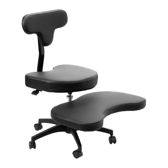
Cross Legged Chair with Wheels
Instruction Manual
SKU: CHAIR-CL02B
Scan the QR code with your mobile device or follow the link
for helpful videos and specifications related to this product.
https://vivo-us.com/products/chair-cl02b
GET IN TOUCH | Monday-Friday from 7:00am-7:00pm CST
help@vivo-us.com
www.vivo-us.com
Chat live with an agent!
309-278-5303
Advertisement

Subscribe to Our Youtube Channel
Related Manuals for Vivo CHAIR-CL02B


Summary of Contents for Vivo CHAIR-CL02B
- Page 1 Cross Legged Chair with Wheels Instruction Manual SKU: CHAIR-CL02B Scan the QR code with your mobile device or follow the link for helpful videos and specifications related to this product. https://vivo-us.com/products/chair-cl02b GET IN TOUCH | Monday-Friday from 7:00am-7:00pm CST help@vivo-us.com www.vivo-us.com...
-
Page 2: Package Contents
WARNING! If you do not understand these directions, or if you have any doubts about the safety of the installation, please call a qualified technician. Check carefully to make sure there are no missing or defective parts. Improper installation may cause damage or serious injury. -
Page 3: Assembly Steps
ASSEMBLY STEPS STEP 1 Connect Casters (J) to underside of Base (A). STEP 2 Secure the Foot Pad (H) to the Lower Support (C) using the M6x20mm Screws (S-A) and 5mm Allen Wrench (T-A). - Page 4 STEP 3 Slide the Gas Spring (B) through the Lower Support (C). Secure using the M8x22mm Screws (S-C) and 5mm Allen Wrench (T-A). Note: The position of the pre-installed collar on Gas Spring (B) should not adjusted. STEP 4 Insert the lower chair assembly into Base (A).
- Page 5 STEP 5 Slide the Back Rest Support (E) into the bracket on the underside of the Seat Pad (G). Choose one of the available mounting positions and secure the Back Rest Support (E) using the M8x30mm Screws (S-D) and 5mm Allen Wrench (T-A). The hole set closer to the middle of the Seat Pad (G) will position the back rest further up, and the rear-set hole position will set the back rest further back.
- Page 6 STEP 7 Attach Back Rest Bracket (I) to Back Rest Pad (F) using M6x16mm Screws (S-B) and 5mm Allen Wrench (T-A). Choose your preferred height on Back Rest Support (E) and secure assembled back rest using Adjustment Screw (D).
- Page 7 STEP 8 Adjust the height of the seat by pulling the handle below the Seat Pad (G). The height of the Foot Pad (H) can be adjusted by loosening the screws on Lower Support (C) using the 5mm Allen Wrench (T-A).
- Page 8 AVG. RESPONSE TIME (within office hrs) - 23% within < 15m - 38% within < 30m - 61% within < 1hr - 83% within < 2hr - 92% within < 3hr FOR MORE VIVO PRODUCTS, CHECK OUT OUR WEBSITE AT: www.vivo-us.com...
Need help?
Do you have a question about the CHAIR-CL02B and is the answer not in the manual?
Questions and answers