
Related Manuals for Texas Instruments BQ24702/03 EVM


Summary of Contents for Texas Instruments BQ24702/03 EVM
- Page 1 bq24702/03 EVM for Multi Chemistry Battery Charge Controller and System Power Selector User’s Guide April 2003 PMP EVMs SLUU160...
- Page 2 IMPORTANT NOTICE Texas Instruments Incorporated and its subsidiaries (TI) reserve the right to make corrections, modifications, enhancements, improvements, and other changes to its products and services at any time and to discontinue any product or service without notice. Customers should obtain the latest relevant information before placing orders and should verify that such information is current and complete.
- Page 3 EVM IMPORTANT NOTICE Texas Instruments (TI) provides the enclosed product(s) under the following conditions: This evaluation kit being sold by TI is intended for use for ENGINEERING DEVELOPMENT OR EVALUATION PURPOSES ONLY and is not considered by TI to be fit for commercial use. As such, the goods being provided may not be complete in terms of required design-, marketing-, and/or manufacturing-related protective considerations, including product safety measures typically found in the end product incorporating the goods.
- Page 4 EVM schematic located in the EVM User’s Guide. When placing measurement probes near these devices during operation, please be aware that these devices may be very warm to the touch. Mailing Address: Texas Instruments Post Office Box 655303 Dallas, Texas 75265 Copyright 2003, Texas Instruments Incorporated...
- Page 5 Information About Cautions and Warnings Preface Read This First About This Manual The bq24702/3 is a highly integrated battery charge controller designed to work with external host commands. It has an integrated PWM charger and system power selector. The charge voltage, charge current, and other system parameters are programmable.
- Page 6 Trademarks The TI Logo is a trademark of Texas Instruments.
-
Page 7: Table Of Contents
Contents Contents Introduction ..............EVM Features . - Page 8 Contents...
-
Page 9: Introduction
Chapter 1 Introduction The bq24702/3 evaluation module is a complete charger module for evaluating a multi-chemistry charge solution using the bq24702/3 devices. It is designed to deliver up to 3 A of current to Li-Ion applications (3 or 4 cells) and NiMH applications (5–10 cells). -
Page 10: Evm Features
EVM Features 1.1 EVM Features Programmable up to 3-A charge current Programmable charge voltage, charge current, battery depleted, system break before make, and ac-adapter detection levels Supports single chemistry and multi-chemistry applications Status outputs: battery depleted and ac-adapter detection TTL-level controls: charge enable and selector mode 1.2 Contents Evaluation module and support documentation Condition... -
Page 11: Optional Components
Optional Components 1.4 Optional Components The bq24702/3 EVM has all components required for robust operation on a wide range of different operating conditions and ac adapter/load transients. However , some of its components might not be required or can be of distinct value, depending on the application condition. -
Page 13: Test Summary
Chapter 2 TEST SUMMARY This chapter provides details on board configurations. Topic Page I/O Description ..........Controls and Adjustable Resistors . -
Page 14: I/O Description
I/O Description 2.1 I/O Description Jack Description J1–POS AC adapter, positive output J1–GND AC adapter, negative output J2–VPUP ALARM/ACPRES pullup input voltage J2–5V Internal 5-V reference output voltage J5–ACPRES ACPRES pin output voltage (ac detection) J5–ALARM ALARM pin output voltage (battery depleted) J5–GNDSNS Kelvin GND connection to EVM clean ground plane J5–SRSET (see Note 3) -
Page 15: Controls And Adjustable Resistors
Controls and Adjustable Resistors 2.2 Controls and Adjustable Resistors Jack Description Factory Setting Charge control, ON at charge disabled Charge disabled System power selector configuration, ON at AC adapter to system battery connected to system Charge voltage reference Internal reference selected 1–2 at external reference 2–3 at internal reference System break before make function, ON at... -
Page 16: Configuration Procedure
Configuration Procedure 2.3 Configuration Procedure This procedure details how to configure the evaluation board, using the EVM as a stand-alone unit, in case the factory settings have to be modified. The board was originally configured as shown in section 2.2. External power sources (20 V, 3 A) , battery pack, 100-Ω/5-W resistor and current load are required to evaluate the board. - Page 17 Configuration Procedure Configuration steps: Step 1: Adjust AC Detection Threshold Set jumpers as follows → J3 ON (charge off) J4 OFF (ac adapter to system) 1) VBAT (J8) open. Connect external supply set to 0 V to J1 (POS/GND), connect 100-Ω resistor between J8 VSYS/GND. 2) Increase supply voltage to desired ac-detection threshold.
- Page 18 Configuration Procedure Step 2: Adjust Battery Depleted Threshold Set jumpers as follows → J3 ON (charge off) J4 OFF (ac adapter to system) 1) Connect external supply set above ac-detection threshold programmed in 1) to J1 (POS/GND). Connect 100-Ω resistor between J8 VSYS/GND.
- Page 19 Configuration Procedure Step 3: Current Limit Setting Set jumpers as follows → J3 ON (charge off) J4 OFF (ac adapter to system) 1) Connect external supply set above ac detection threshold programmed in 1) to J1 (POS/GND). 2) Adjust R10 monitoring V(SRSET) to program the charge current limit: Note: ICHG (typ) = [V(SRSET) / 25] / (0.025) 3) Adjust R8 monitoring V(ACSET) to program the ac adapter...
- Page 20 Configuration Procedure 7) Set J3 ON (charge disabled). Verify → Charge is off, I(VBAT) < 0 (battery sourcing current) → AC adapter switched to VSYS , V(TP1)=VSYS 8) Set J3 OFF (charge enabled) and J4 ON (battery to system). Verify → Charge is off →...
-
Page 21: Using Additional Functions
Chapter 3 Using Additional Functions This chapter describes the use of the break-before-make function (VS pin). Topic Page System Break-Before-Make ........External Pullup for ALARM/ACPRES Outputs . -
Page 22: System Break-Before-Make
System Break-Before-Make 3.1 System Break-Before-Make The system break-before-make function (VS pin) can be enabled by: → Setting J9 open (break-before-make enabled). The configuration procedure to set the break-before-make threshold is as follows: 1) Connect power supply to J8 between VBAT and GND. V(POS) (J1) open 2) Adjust VBAT = programmed break-before-make threshold 3) Adjust R28 until V(TP17) = 1.196 V. -
Page 23: Example: Configuring Bq24702/3 For A 3-Cell Li-Ion Pack
Chapter 4 Example: Configuring bq24702/3 for a 3-Cell Li-Ion Pack This chapter describes the configuring the bq24702/3 for a 3-cell Li-Ion Pack. Design parameters: Charge current limit = 2 A DPM current limit = 3 A AC adapter threshold = 16 V Battery depleted threshold = 9 V System break-before-make threshold equal to pack voltage Topic... -
Page 24: Configuration Procedure
Configuration Procedure 4.1 Configuration Procedure Step 1: Adjust AC Detection Threshold Set jumpers as follows → J3 ON (charge off) J4 OFF (ac adapter to system) 1) VBAT (J8) open. 100-Ω resistor between J8 VSYS/GND, V(POS) = 16 V. 2) Adjust R12 to obtain V(TP2)=1.23 V ±1 mV. 3) V(POS) = 14 V, Measure →... - Page 25 Configuration Procedure Step 4: Charge Voltage Setting Set jumpers as follows → J3 ON (charge off) J4 OFF (ac adapter to system) 1) V(VBAT) = 12.6 V, V(VPOS) = open, no load at VSYS. 2) Adjust R25 until V(TP14)=1.196 V ±1 mV 3) V(POS) = 18 V, V(VBAT) = open, no load at VSYS.
- Page 26 Configuration Procedure Step 6: System Break-Before-Make Set jumpers as follows → J3 ON (charge off) J4 OFF (ac adapter to system) 1) J9 open (break-before-make enabled) 2) V(POS) = 18 V, V(VBAT) = 12.6 V ±1 mV, no load at VSYS 3) Adjust R28 until V(TP17) = 1.196 V Measure: →...
-
Page 27: Bill Of Materials, Board Layout, And Schematics
Chapter 5 Bill of Materials, Board Layout, and Schematics Topic Page Bill of Materials ..........Board Layout . -
Page 28: Bill Of Materials
Bill of Materials 5.1 Bill of Materials COUNT RefDes DESCRIPTION SIZE PART NUMBER Capacitor, tantalum, 4.7 µF, 16 V, C1, C5 TANTALUM-A Panasonic ECS–T1EX475R Capacitor, ceramic, 180 pF, 50 V, Kemet C0805C181J5GACTU X7R, 10% Capacitor, aluminum, 22 µF, 35 V, 0.335 ×... - Page 29 Bill of Materials COUNT RefDes DESCRIPTION SIZE PART NUMBER Resistor, chip, 0.00 Ω, 1/10–W Resistor, chip, 10, 1/10–W, 5% Resistor, chip, 750 Ω, 1W, 5% 2512 Vishay CRCW2512751J R2, R3, R4, Resistor, chip, 100 K, 1/10–W, 1% Vishay CRCW0805–1003–F R5, R6, R7, R9, R26 Resistor, chip, 750 Ω, 1/10W, 1% Vishay...
-
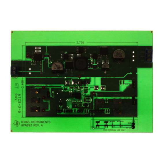
Page 30: Board Layout
Board Layout 5.2 Board Layout 4.750 TP16 TP13 TP12 3.400 R219 TP17 C7 C8 TP15 TP10 TP14 TP11 Top Assembly 4.750 3.400 Layer 1... - Page 31 TP14 CURRENT LIMIT VOLTAGE EXT ON INT ON BATT. DEPLETED AC ADAPTER CURRENT LIMIT CHGOFF BAT SYS TP11 ALARM ACPRESS TEXAS INSTRUMENTS bq24702/bq24703 EVM HPA006 REV. A FOR EXTERNAL USE ONLY Silk Screen Bill of Materials, Board Layout, and Schematics...
- Page 32 Board Layout 4.750 3.400 HPA006 REV.A BOTTOM ASSY Bottom...
- Page 33 Schematics 5.3 Schematics The schematic is shown on the following page. Bill of Materials, Board Layout, and Schematics...
Need help?
Do you have a question about the BQ24702/03 EVM and is the answer not in the manual?
Questions and answers