
Related Manuals for Bionet CardioCare2000


Summary of Contents for Bionet CardioCare2000
- Page 1 CardioCare2000 Operation Manual Ver. 3.22 2022.01.18 www.ebionet.com Copyright © 2022 By Bionet CO., LTD. All rights reserved...
- Page 2 V 3.22 Warranty - This product was made through strict quality control and examination. The repair and compensation standards follow the consumer damage compensation regulations of the Ministry of Finance and Economy. - The warranty for this product runs for 1 year. (2 years in EU) But the warranty for accessories runs for 6 months.
- Page 3 Email: infor@cmcmedicaldevices.com Website: http://www.cmcmedicaldevices.com/ ※ In the event of a malfunction or failure, contact Service Dept. Of Bionet Co., Ltd . along with the model name, serial number, date of purchase and explanation of failure. 2022. 01 3 / 79...
- Page 4 V 3.22 Fee-Based Service If you wish to make a claim when the product is damaged thr ough misuse, we charge repair fees. Please read the manual before you make a claim. - For simple inspection without giving instruction or Fee charged: From the disassembling the product second time...
- Page 5 V 3.22 Definition of WARNING, CAUTIONS and NOTE In order to stress the contents of this manual, we define the terms as below. ⚫ Please follow the warning and cautions instruction. ⚫ The manufacturer or service agents are not responsible for damage resulting from inappropriate use or carelessness.
- Page 6 V 3.22 Environment Instructions Please do NOT use or place the product in such environments explained below. Steamy environment. Do not use the Direct sunlight. product with wet hands. Place where the temperature and humidity condition are extreme Near electronic (Use the equipment heaters between the ambient...
- Page 7 It is not proper to use this product near a flammable anesthetic or solvent. Continuous operation. IEC/EN60601-1-2 (Electromagnetic Compatibility Requirements) standard: Class A NOTE Diagnosis provided by CardioCare2000 must be confirmed by a qualified medical professional. 2022. 01 7 / 79 Doc. # : BN-CC2-OPM...
- Page 8 V 3.22 NOTE Additional equipment connected to medical electrical equipment must comply with the respective IEC or ISO standards (e.g. IEC 60950 for data processing equipment). Furthermore, all configurations shall comply with the requirements for medical electrical systems (see IEC 60601-1-1 or clause 16 of the 3 Ed. of IEC 60601-1, respectively).
- Page 9 WARNING Portable RF communications equipment (including peripherals such as antenna cables and external antennas) should be used no closer than 30 cm (12 inches) to any part of the CardioCare2000, including cables specified by the manufacturer. NOTE The EMISSIONS characteristics of this equipment make it suitable for use in industrial areas and hospitals (CISPR 11 class A).
- Page 10 V 3.22 Safety Symbols Symbols Contents ATTENTION: Consult accompanying documents Consult instructions for use: This symbol advises the reader to consult the operating instructions for information needed for the proper use of the device. Safety Sign: To signify that the instruction manual must be read. Reading the instruction manual before starting work or before operating equipment.
- Page 11 V 3.22 Symbols Contents Local Area Network (LAN) Connector Power Off Power On Battery Operation Indicator AC Power Connection Indicator Manufacturer name and address Authorized European representative Waste of electrical and electronic equipment must not be disposed as unsorted municipal waste and must be collected separately. Please contact an authorized representative of the manufacturer for information concerning the decommissioning of your equipment.
-
Page 12: Table Of Contents
V 3.22 Contents Chapter 1. General Information .......... 13 1) Product Overview ..............14 2) Indication for Use ..............14 3) Recording ECGs during Defibrillation ........15 4) Product Features ............... 15 5) Product Configuration .............. 16 6) System Installation ..............28 7) Menu Structure ................ -
Page 13: Chapter 1. General Information
V 3.22 Chapter 1. General Information 1) Product Overview 2) Indications for Use 3) Recording ECGs during defibrillation 4) Product Features 5) Product Configuration Basic Components and Accessories Optional components Body Configuration LCD Panel Control Panel Power 6) System Installation Precautions for Installation Power Connection Patient Cable Connection... -
Page 14: Product Overview
QRS and P wave portions of the electrocardiogram. Transmission and reception of ECG data to and from a central ECG cardiovascular information system is optional. The CardioCare2000 is intended to be used under the direct supervision of a licensed healthcare practitioner, by trained operators in a hospital or medical professional’s facility. -
Page 15: Recording Ecgs During Defibrillation
V 3.22 infarction as well. In addition to its usefulness in ischemic coronary disease, the ECG, in conjunction with ambulatory ECG monitoring, is of particular use in the diagnosis of disorders of the cardiac rhythm and the evaluation of syncope. Contraindications No absolute contraindications to performing an electrocardiogram, other than patient refusal, exist. -
Page 16: Product Configuration
V 3.22 5) Product Configuration The CardioCare2000 system consists of the items below. Unpack the package and check the items below are included. Also, be sure to check for any damage to the body and accessories. Basic Components and Accessories ①... - Page 17 V 3.22 Optional components ① ① Battery (1 EA): Replaceable and Rechargeable, Lithium ion, 3BL335-BIO-4 (10.8V, 3250mAh) CAUTIONS You may have distortion or signal noise when you use nonstandard or other brand accessories. We strongly recommend you use only the authorized accessories which we supply.
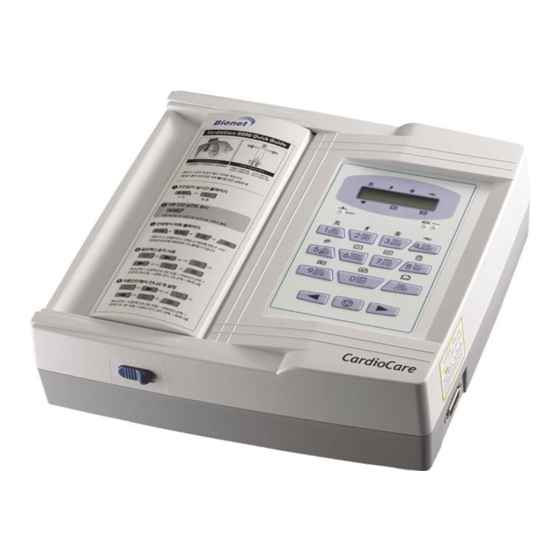
- Page 18 V 3.22 Body Configuration ▣ Top View ① ② ③ ④ ⑤ ① Handle ② Printer Cover ③ Printer Cover Switch ④ LCD ⑤ Control Panel 2022. 01 18 / 79 Doc. # : BN-CC2-OPM...
- Page 19 V 3.22 ▣ Front View ① ① Printer Cover Switch ▣ Rear View ① ② ③ ④ ⑤ ① Protective Ground Terminal ② Power Switch ③ AC Power Connection Port (+ Fuse (250V, 3.15AL) x 2) ④ USB Port (Use for equipment upgrades only) ⑤...
- Page 20 Do not use the product and immediately ask the manufacturer and the seller for repair NOTE To avoid an expected electric shock, do not open the equipment cover or disassemble the equipment. Refer servicing to Bionet, Inc. 2022. 01 20 / 79 Doc. # : BN-CC2-OPM...
- Page 21 V 3.22 LCD Panel LCD panel displays system setting status after indicating the version of the system and manufacturer name for 2 seconds when power is turned on. Displayed items on the LCD are as follows. ① ② ③ ④ ⑤...
- Page 22 V 3.22 Control Panel ▣ Indicator Lamp I Indicate the lead connection status. If LED is illuminated green, connection status is good. If LED is off, connection status is bad. In this case, check off which one of lead connection is in lead-off status through monitor mode output.
- Page 23 V 3.22 ▣ Short Key Select signal level(mm/mV) out of 5, 10, 20, aut (I-aVF:10, V1-V6:5) Select printing speed(mm/sec) out of 12.5, 25, 50 Select off, 0.05, 0.1, 0.2Hz whether or not to activate the filter that eliminates baseline drift Select on or off whether or not to activate the filter that eliminates EMG.
- Page 24 V 3.22 Move the selected focus to the left in menu mode Move the selected focus to the right in menu mode 2022. 01 24 / 79 Doc. # : BN-CC2-OPM...
- Page 25 V 3.22 Power ▣ AC Power When AC power is supplied to the equipment, AC power indicator lamp at the front side is illuminated green and battery is being charged automatically. Battery charge AC Power indicator lamp indicator lamp If no battery is installed, battery indicator lamp will be off. Once a battery is plugged in and the device is powered on, it will change its power mode to supply power to the battery.
- Page 26 When AC power is connected in the monitor equipment, the battery doesn't work and doesn't supply power. Battery life may be less than 12 months. Bionet recommends it should be kept separate from the equipment during the moving.
- Page 27 V 3.22 Battery recycles Replace the battery when it is no longer charged. This battery is a regenerative product. Remove the battery from the system and put it in a separate bin. WARNING Don't keep at high temperatures or burned of a battery due to there is a risk of explosion. You can wear serious injuries resulting from the explosion.
-
Page 28: System Installation
Paper Installation - Push the printer cover release switch to the right to open the printer door of the CardioCare2000. Install ECG paper with the side to be recorded appearing on top. Close the cover to finish the paper installation process. - Page 29 - If the device is used as a layer-2-switch or layer-3-switch, the port settings must be configured on the network switch. “Bionet device” must be configured so that the network settings are compatible with the specifications of the operating organization.
-
Page 30: Menu Structure
V 3.22 7) Menu Structure CardioCare2000 system provides 3 basic modes with preparation mode, output mode, and menu mode. Preparation mode is an initial condition when system starts operating. LCD displays system settings and heart rate. In preparation mode, system setting can be changed by pressing each short key SENS, SPD, BASE, MUSC, FORM, LEAD, PAT, MON, REC, COPY of the control panel. -
Page 31: System Setting
V 3.22 8) System Setting Initial Setting Press 7key of the control panel for 3 seconds to initialize the system at the factory preset. After 5 seconds, following window message appears on the LCD for 1sec and system sets to initialize. * FACTORY MODE * initialize Initialized details are as follows:... - Page 32 To set the time of CardioCare2000, move the menu to SYS → TIME → * TIME SETUP * as shown above. Then enter the time in the same way date is entered. 2022. 01 32 / 79 Doc.
- Page 33 V 3.22 User Identification User identification is to enter the hospital name and doctor name that operates the system. To enter the hospital name, move the menu to * ENTER HOSP. * as following steps. PAT FLT PRN SYS < SYStem setup > SYS select -- DATE TIME HOSP>>...
- Page 34 V 3.22 QRS Sound Setup In this menu, users can set the device to ring an alarm sound when a QRS beat has generated while it is in waiting mode. To set the QRS Sound, moves the menu to QRS as following steps.
- Page 35 V 3.22 Lead fault LED Setting When the connection between the patient and Leads is improper, lead fault can occur. In that case, you can choose whether to have the lead fault LED on the device or not. To set the lead fault LED, moves the menu to L/F as following steps. PAT FLT PRN SYS <...
- Page 36 V 3.22 Network Setting User identification is to enter the hospital name that operates the system. To enter the hospital name, move the menu to IP as following steps. PAT FLT PRN SYS < SYStem setup > SYS select -- <<...
- Page 37 V 3.22 Language To set a language for CardioCare2000, move the menu to LANG as following steps. PAT FLT PRN SYS < SYStem setup > SYS select -- << LANG UPGRADE ENGLISH Language select -- key switches language. (English, English-US, Chinese, German, French, Russian, Spanish, Italian, Turkish, Polish, Romanian and Portuguese) 2022.
-
Page 38: Chapter 2. Preparation For Ecgs Recording
V 3.22 Chapter 2. Preparation for ECGs Recording 1) Electrode positions 2) Electrode Connection Patient Cable Connection How to Attach Electrodes Countermeasures for Bad Lead Connection 2022. 01 38 / 79 Doc. # : BN-CC2-OPM... -
Page 39: Location Of Electrodes
V 3.22 1) Location of Electrodes Attach electrodes to the patient’s body to record an electrocardiogram of twelve standard leads [ I, II, III, aVR, aVL, aVF, V1, V2, V3, V4, V5, V6], as shown below. Limb electrodes are located as follows. - RL (N): Right Leg - LL (F): Left Leg - RA (R): Right Arm... -
Page 40: Electrode Connection
ECG signals. WARNING Use only electrodes and patient cables provided from Bionet, Inc. Bionet America, Inc. will take no responsibility for any accidents involving 3 party accessories. - Page 41 - Second case, signal conductivity between leads and the patient’s body is low. In this case, replace the electrodes. If the two above cases have been performed and the operator is still experiencing noise or lead fault conditions, the patient cable may be faulty. Please contact the Bionet service center. 2022. 01 41 / 79 Doc.
-
Page 42: Chapter 3. Recording Of Ecgs
V 3.22 Chapter 3. Recording of ECGs 1) Introduction 2) Basic Setting General Information Signal Level Setting Signal Speed Setting Filter Setting Channel form Setting Rhythm Channel Setting Grid Setting Monitoring form Setting Monitoring Channel Setting Diagnosis On/Off Setting Enter Patient Data 3) Monitor Mode Output Output Method Output Form... -
Page 43: Introduction
V 3.22 1) Introduction 1. Turn the power switch on after connecting leads to the patient according to preparation for ECGs recording of Chapter 2. 2. Set the filter, signal level, display speed, channel form, rhythm lead according to “Basic Setting” of Chapter3. 3. -
Page 44: Basic Setting
V 3.22 2) Basic setting General Information LCD displays current system setting in the order of signal level, printing speed, baseline filter, EMG filter, heart rate, channel form, rhythm channel when system is turned on. These settings can be changed by two kinds of methods. First method is to use short keys. System setting can be easily changed by pressing short keys of control panel that accord with the icons displayed on the LCD screen. - Page 45 V 3.22 Filter Setting AC power noise, baseline drift caused by breathing, EMG signal can be recorded along with the output ECG signal. To set the AC noise filter, move to “FLT” menu to call up “AC” menu and press key.
- Page 46 V 3.22 Channel form Setting Channel form setting is to adjust the numbers of channel of output form. This system provides four kinds of channel form of 3ch+1rhy, 6ch+1rhy, 12ch rhy, 60s 1rhy. As for 3ch+1rhy, 10 seconds of ECG data are recorded in four consecutive segments of 2.5 seconds such as I, II, III for first 2.5 seconds time segment, aVR, aVL, aVF for second 2.5 seconds time segment, V1,V2, V3 for third 2.5 seconds time segment, V4, V5, V6 for last 2.5 seconds segment.
- Page 47 Grid is marked with solid line of 5mm X 5mm and with dot of 1mm X 1mm position. In case of using standard ECG recording paper supplied from Bionet Co. Ltd instead of using fax sheet, grid setting should be off because grid is already marked on recording paper.
- Page 48 V 3.22 Monitoring form Setting You can set up the real time printing size. To set the monitoring form, moves the menu to * MONI * as following steps. PAT FLT PRN SYS < PRiNter setup > FORM LEAD MONI CONTINUE key switches continue or A4 report.
- Page 49 V 3.22 Monitoring Channel Setting Monitoring channel setting is to adjust the numbers of channel of monitoring form. This system provides four kinds of channel form of 3ch, 6ch, 12ch. To set the monitoring channel, moves the menu to * M-CH * as following steps. PAT FLT PRN SYS <...
- Page 50 V 3.22 Diagnosis On/Off Setting When you print out the diagnosis report, you can choose the result of diagnosis is printed out or not on the report. To set the diagnosis, moves the menu to * DIAG * as following steps. PAT FLT PRN SYS <...
- Page 51 V 3.22 Enter Patient Data Patient information including patient ID, name, age, sex, height, weight can be entered. There are two methods to enter patient data. First, move the menu to patient data menu by pressing PAT key. Second, move the menu to “ID” as following steps. PAT FLT PRN SYS <...
- Page 52 V 3.22 All the other patient data are deleted with selecting yes and then move the menu to “ENTER ID” for new patient data entry. Previous patient data are displayed on the LCD as follows with selecting no: New Patient? Select No ID NAME AGE >>...
- Page 53 V 3.22 Patient ID can be entered in up to 16 characters. ID number is entered by pressing 0, …, 9 numeric keys in the current cursor position. Wrongly typed number can be deleted with ◁ key. Use ▷ key to enter ‘–‘. ID entry can be combined with numbers of 123-456-789 and ‘-’.
- Page 54 V 3.22 To enter age, move the menu to “ENTER AGE” as following step: PAT FLT PRN SYS < PATient info. > PAT Select ID NAME AGE > > Select Age * Enter AGE* years Age can be entered in up to 3 figures. Age is entered by the unit of year. Age is entered with pressing 0, …, 9 numeric keys in the current cursor position and cursor automatically moves to the right.
- Page 55 V 3.22 To enter sex, move the menu to “ENTER SEX” as following steps: PAT FLT PRN SYS < PATient info. > Select PAT << SEX HEI WEI Select SEX * Enter Sex * male female Sex can be selected between male and female with ◁▷ key. To exit sex press key or ESC key that moves to the menu above.
- Page 56 V 3.22 To enter weight, move the menu to “ENTER WEIGHT” as following steps: PAT FLT PRN SYS < PATient info. > Select PAT << SEX HEI WEI Select WEI * Enter Weight * Weight can be entered in up to 3 figures. Weight is entered by the unit of kg. Weight is entered with pressing 0, …, 9 numeric keys in the current cursor position and cursor automatically moves to the right.
-
Page 57: Monitor Mode Output
V 3.22 3) Monitor mode output In monitor mode output, the measured ECGs is displayed in real-time. This output function can be used for the purpose of checking out that the entire channel signal is active before recording ECGs and monitoring ECGs of the patient for long time. Printing speed can be set to 12.5 mm/s, 25mm/s, 50mm/s and signal level can be set to 5mm/mV, 10mm/mV, 20mm/mV, aut. -
Page 58: Record Mode Output
V 3.22 4) Record mode output In record mode output, ECGs is recorded on the memory first and displayed according to the selected signal level, output display speed, channel form after applying the selected filter and calculating the measurement parameter including heart rate, PR interval, QRS duration, QT/QTc, P-R-T axes of the recorded ECGs. - Page 59 V 3.22 60 seconds ECG Recording Press key when channel form is set to 60s 1rhy. Then, the system starts recording data on the selected rhythm channel for 60 seconds on the memory with the following message indicates recording time on the LCD. * RECORD(10s) * 60 sec After recording data for 60 seconds, the system starts applying the selected filter and...
- Page 60 V 3.22 Output form The printing forms are described and the example of printing form by each channel form is provided below. RHYTHM REPORT FORM 2022. 01 60 / 79 Doc. # : BN-CC2-OPM...
- Page 61 V 3.22 RECORD REPORT FORM (3ch+1rhy) 2022. 01 61 / 79 Doc. # : BN-CC2-OPM...
- Page 62 V 3.22 RECORD REPORT FORM (6ch+1rhy) 2022. 01 62 / 79 Doc. # : BN-CC2-OPM...
- Page 63 V 3.22 RECORD REPORT FORM (12ch rhy) 2022. 01 63 / 79 Doc. # : BN-CC2-OPM...
- Page 64 V 3.22 RECORD REPORT FORM (60s 1rhy) Output form These are the explanation of the output form and examples according to each channel form. 2022. 01 64 / 79 Doc. # : BN-CC2-OPM...
-
Page 65: Copy Mode Output
V 3.22 5) Copy mode output Copy mode output function is to print the same report as previously printed one or print after changing setting such as filter, signal level, output display speed, channel form, rhythm cannel of previously recorded ECG data. System starts printing the same report as previously printed one with the following message on the LCD by pressing key after record mode printing. - Page 66 Use the provided ECG patient cable for measuring ECG in the operating room. Patient cable cannot be used for measuring respiration. CAUTIONS Do not use CardioCare2000 in combination with any Electro-Surgical (ES) equipment. CAUTIONS Users must use same type of electrode or any other biocompatibility certified ones that have been proved by International Standard.
-
Page 67: Chapter 4. System Management
V 3.22 Chapter 4. System Management 1) Maintenance and Cleaning 2) Regular Check-up 3) Trouble Shooting 4) Manufacturer Declaration 2022. 01 67 / 79 Doc. # : BN-CC2-OPM... -
Page 68: Maintenance And Cleaning
V 3.22 1) Maintenance and Cleaning There are many ways to clean CardioCare2000, but it is best to use our recommendation to avoid damage or sanitary issues. The warranty does not cover problems resulting from the use of harmful substances (unauthorized substances). -
Page 69: Trouble Shooting
V 3.22 3) Trouble Shooting 1. In case that buzzer alarms for 1 second during printing and following message appears on the LCD: * RECORD * Paper empty! This indicates that printer run out of printing paper. Operate again after replacing printing paper. -
Page 70: Manufacturer Declaration
V 3.22 4) Manufacturer Declaration Electromagnetic Compatibility Information Basic EMC Phenomenon standard or test Test level/requirement method Mains terminal CISPR 11 Group1, Class A disturbance voltage Radiated disturbance CISPR 11 Group1, Class A Harmonic Current Emission IEC 61000-3-2 Class A Pst: 1 Voltage change, Plt: 0.65... - Page 71 Electromagnetic compatibility - Guidance and manufacturer's declaration Guidance and manufacturer’s declaration – electromagnetic emissions The CardioCare2000 is intended for use in the electromagnetic environment specified below. The customer or the user of the CardioCare2000 should assure that it is used in such an environment. Emissions test...
- Page 72 V 3.22 Guidance and manufacturer’s declaration – electromagnetic immunity The CardioCare2000 is intended for use in the electromagnetic environment specified below. The customer or the user of the CardioCare2000 should assure that it is used in such an environment. IMMUNITY...
- Page 73 V 3.22 Guidance and manufacturer’s declaration – electromagnetic immunity The CardioCare2000 is intended for use in the electromagnetic environment specified below. The customer or the user of the CardioCare2000 should assure that it is used in such an environment. IEC 60601...
- Page 74 RF transmitters, an electromagnetic site survey should be considered. If the measured field strength in the location in which the CardioCare2000 is used exceeds the applicable RF compliance level above, the CardioCare2000 should be observed to verify normal operation.
- Page 75 V 3.22 For transmitters rated at a maximum output power not listed above, the recommended separation distance d in meters (m) can be estimated using the equation applicable to the frequency of the transmitter, where P is the maximum output power rating of the transmitter in watts (W) according to the transmitter manufacturer.
-
Page 76: Chapter 5. Specification
V 3.22 Chapter 5. Specification ECG Leads Simultaneous 12 Leads Resting ECG Recording Channel 3CH+1RHY, 6CH+1RHY, 12CH, 1CH Long Time (1min) Gain 5, 10, 20, Auto (I~aVF: 10, V1~V6: 5) mm/mV Printing Speed 12.5, 25, 50 mm/sec Sampling Rate Analysis Sampling Rate – 500sample/sec Digital Sampling Rate - 8,000sample/sec Filters AC (50/60Hz, -20dB or better),... - Page 77 V 3.22 Communication Safety Conformity Class I, Type CF Defibrillation-proof applied Part. Environ Operation Ambient Temperature: 10~40℃ mental Relative Humidity: 30~85%RH Atmospheric Pressure: 70~106KPa Storge/Ship Ambient Temperature: -20~60℃ Relative Humidity: 10~95%RH Atmospheric Pressure: 50~106KPa Dimensions 300(W) x 290(D) 97(H)mm, Approx. 3.0kg (Main Body) Standard Accessory Patient Cable (1 EA), Limbs Electrodes (1 SET), Chest Electrodes (1 SET), ECG Paper (1 EA),...
- Page 78 Contact No: Seller’s Name Manufacturer’s Name Bionet Co., Ltd ※ Thanks for purchasing CardioCare2000. ※ This product is a medical machine. ※ This product meets the strict quality requirements thoroughly. ※ The repairing and compensation standards follow the consumer damage compensation regulations of the Ministry of Finance and Economy.
- Page 79 Authorized European representative CMC Medical Devices & Drugs S.L.: Horacio Legno N° 18, CP 29006, Malaga, Spain Tel: +34-951-214-054/ Fax: +34-952-330-100 / e-mail: infor@cmcmedicaldevices.com Website: http://www.cmcmedicaldevices.com/ Bionet Co., Ltd Model Name: CardioCare2000 2022. 01 79 / 79 Doc. # : BN-CC2-OPM...
Need help?
Do you have a question about the CardioCare2000 and is the answer not in the manual?
Questions and answers