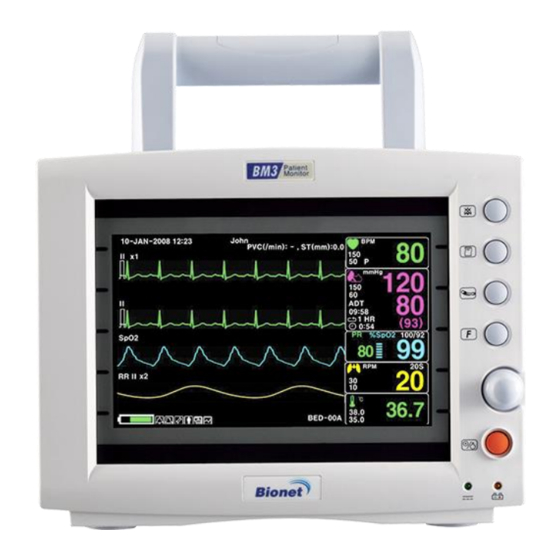
Bionet BM3 User Manual
Patient monitor
Hide thumbs
Also See for BM3:
- User manual (235 pages) ,
- Operation manual (226 pages) ,
- Service manual (62 pages)

Related Manuals for Bionet BM3


Summary of Contents for Bionet BM3
- Page 1 BM3 User’s Manual User’s Manual Patient Monitor Rev. 3.0 2019.11.22 Warning To ensure proper use of this medical equipment, you must read and comply with this user manual.
- Page 2 Reproduction in any manner, in whole or in part, except for brief excerpts in reviews and scientific papers, is prohibited without prior written permission of Bionet, Co., Ltd. Before using Bionet devices, read all the manual that are provided with your device carefully. Patient monitoring equipment, regardless of the complexity of the equipment, should never be used as a substitute for the patient care, attention, and critical judgment that only trained health care professionals can provide.
-
Page 3: Table Of Contents
BM3 User’s Manual Table of Contents Intended Use ............................... 9 General Description ............................9 Patient Classification ........................... 10 Functional safety ............................10 Warning, Caution, Note ..........................11 Define groups ..............................12 General precaution on environment ....................13 Electromagnetic Compatibility ....................... 14 1. - Page 4 BM3 User’s Manual Monitor configuration ..........................34 Main menu setup ............................35 3. Network ................................. 41 Overview ................................ 41 Network connection ..........................41 Remote View ............................... 42 Display Mode .............................. 44 4. Admission and Discharge ........................46 Overview ................................ 46 Patient admission .............................
- Page 5 BM3 User’s Manual 7. ECG ................................... 67 Overview ................................ 67 ECG Precaution ............................68 Patient preparation ..........................71 ECG lead ................................. 72 ECG signal processing and display....................73 ST signal processing and display ..................... 74 Alarm and alarm status ......................... 74 Display................................
- Page 6 BM3 User’s Manual RESP precaution............................90 Patient Preparation ..........................91 Display................................93 RESP Settings .............................. 94 OxyCRG monitoring ..........................94 11. NIBP ................................97 Overview ................................ 97 Display................................99 NIBP Settings ............................100 Measurement Limitations ........................103 Status Messages ............................105 12.
- Page 7 BM3 User’s Manual Thermal Paper Storage ........................128 Paper Change ............................129 15. Maintenance and Troubleshooting ................... 130 Inspection Equipment ........................... 130 Inspection Cables ............................ 130 Maintenance Task and Test Schedule ..................131 Noise in ECG .............................. 133 SpO2 malfunction ........................... 134 Temperature malfunction ........................
- Page 8 BM3 User’s Manual Guidance and manufacturer’s declaration - electromagnetic immunity ....152 System Specification ..........................154 Adult & Pediatric-ICU Mode ........................160 Alarm level ..............................160 Neonate-ICU Mode ............................161 Alarm level ..............................161 Parameter Limits ............................162 Display ................................163 Abbreviations and Symbols ........................
-
Page 9: Intended Use
This equipment is connected via BM central. Note All Bionet hardwares and screenshots in this user guide are for illustration purposes only. Actual products or screens may vary slightly. General Description... -
Page 10: Patient Classification
BM3 User’s Manual Patient Classification BM3 monitors are designed for use by adults, pediatrics and neonates. At this time, cardiac output, ST segment analysis and arrhythmia should be used for adults and pediatrics only. Functional safety The essential performance of the patient monitor is to provide the clinician with meaningful parameter values and to sound an alarm when the established parameter value is exceeded or the function that provides the value is not working properly. -
Page 11: Warning, Caution, Note
BM3 User’s Manual Warning, Caution, Note The following terms are defined in the User Guide to emphasize the agreement as follows: The user must follow all warnings and precautions. The specifications and functions shown in this manual are subject to change without prior notice. -
Page 12: Define Groups
BM3 User’s Manual Define groups The define groups for this product are users, service personnel, and experts. Define groups should read the user manual before using the product and be trained in the use, installation, reprocessing, maintenance and repair of the product. -
Page 13: General Precaution On Environment
BM3 User’s Manual General precaution on environment Do not keep or operate the equipment in the environment listed below. Avoid placing in an area exposed to moist. Avoid exposure to Do not touch the direct sunlight equipment with wet hand. -
Page 14: Electromagnetic Compatibility
The monitor complies with the following standards pertaining to EMI emissions and susceptibility: EN60601-1-2. To reduce possible problems caused by electromagnetic interference, we recommend the following: Use only Bionet approved accessories. Ensure that other products used in areas where patient monitoring and life ... -
Page 15: Basic
Please check the following before using the product. 1. Be sure that AC power supply line is appropriate to use. (AC100 - 240V) 2. Be sure that the power source is the one supplied from Bionet.(DC18V, 2.8A, BPM050 Made in BridgePower Co., Ltd.) 3. - Page 16 Note BM3 is classified as follows: - BM3 classifies as Class II, BF & CF concerning electric shock. It is not proper to operate this Equipment around combustible anesthetic or dissolvent. - Noise level is A class regarding IEC/EN 60601-1 and the subject of Nose is A level concerning IEC/EN60601-1-2.
-
Page 17: Biocompatibility
If you have questions about this matter, please contact Bionet or its representatives. Product Configuration 1. Main body of BM3 Monitor 1 EA 2. -
Page 18: Option Product
Warning In order to avoid electrical shock, do not open the cover. Disassembling of the equipment should be done only by the service personnel authorized by Bionet Warning Users must pay attention on connection any auxiliary device via LAN port or nurse calling. -
Page 19: Basic Unit
BM3 User’s Manual Basic Unit Front view Alarm lamp handle Home key Alarm control key Rotary knob key Printer key Power ON/OFF Key Blood-pressure measurement key Battery status indicator --------------------------------------------------------------------------------------------------------------------------------------- Rev. 3.0... - Page 20 BM3 User’s Manual Right side view ECG connector Blood pressure Hose connector SpO2 connector Temperature connector EtCO2 connector --------------------------------------------------------------------------------------------------------------------------------------- Rev. 3.0...
- Page 21 BM3 User’s Manual Left side view Printer --------------------------------------------------------------------------------------------------------------------------------------- Rev. 3.0...
- Page 22 BM3 User’s Manual Back side view Potential equivalent NURSE CALL connector USB connector (USB 2.0 5Vdc / Max. 500mA), DC input Service port connector Network connector HDMI output --------------------------------------------------------------------------------------------------------------------------------------- Rev. 3.0...
- Page 23 BM3 User’s Manual Warning USB Compatible The BM3 is compatible with external USB memory drives up to 64GB. We recommend brands products listed in the manual (Sandisk, PNY, Transcend, Samsung). When using a product with high power consumption, such as an external hard ...
-
Page 24: Device Markings
BM3 User’s Manual Device Markings Caution : Ground terminal Consult accompanying documents TYPE CF APPLIED PART TYPE BF APPLIED PART Printer Auxiliary Port LAN port HDMI HDMI external port DC Input Indicator USB port Battery Operation indicator DC input connector... -
Page 25: Power
BM3 User’s Manual Power The BM3 monitor uses a DC adapter (100-240 VAC / 18VDC 2.8A). In the event of a power outage or cable shortage, the monitor automatically switches to battery power to continue patient monitoring without data loss. The built-in battery is intended for back- up use only during power-off. - Page 26 BM3 User’s Manual Operation 1. Battery Power LED is lighted on when the machine is in use. 2. Battery is automatically charged when the machine is connected to DC Power Supply. The charging status is displayed at the top right of the screen 3.
- Page 27 To maximize the charge for transport, keep the monitor connected until you are ready to transport the patient. Reconnect the monitor immediately after transport. Bionet recommends replacing the lithium ion battery after 24 months of use. Battery life depends on usage. If battery life continues, battery life will ...
- Page 28 Warning Be careful of the polarity when replacing the battery. We strongly recommend that you use the battery supplied by Bionet. Using unauthorized batteries may damage the equipment 5. Presence of battery: When the battery is disconnected from the equipment and it malfunctions, it shows 'X' as shown below.
-
Page 29: How To Replace The Battery
BM3 User’s Manual How to replace the battery Please assemble and replace as shown below. The Impact of Lithium-Ion Battery Technology on the Battery The following are the key points you should know about Lithium-Ion battery technology: The battery will discharge on its own, even when it is not installed in a monitor. This discharge is the result of the Lithium-Ion cells and the bias current required for the integrated electronics. - Page 30 12 months. Bionet recommends that you remove the battery and store it near the monitor until it is needed for transport.
-
Page 31: Getting Started
BM3 User’s Manual Getting Started Starting the monitor: Press the power key (O) at the bottom right of the monitor front panel. The power light on the monitor lights up, the alarm bar lights up, the power is turned off, the screen lights up, the main screen is displayed after running the self-test. - Page 32 BM3 User’s Manual The parameter box displays values, alarm limits and icons for the selected parameter. You can set the parameters and their associated waveforms so that they are easy to distinguish. The message appears at the top of the screen. The patient name bed label is displayed in the upper left corner of the screen.
- Page 33 BM3 User’s Manual Function key On the right side of the monitor's front panel, the touch screen icon on the touch screen allows you to perform frequently-used functions. Fixed key Description Fixed key Description Opens a table where you This is an alarm mode key, so...
-
Page 34: Setup
BM3 User’s Manual 2. SETUP Overview This chapter describes how to configure your monitor and how to upgrade your software. Monitor configuration Setup Menu tree Parameter menu tree --------------------------------------------------------------------------------------------------------------------------------------- Rev. 3.0... -
Page 35: Main Menu Setup
BM3 User’s Manual Main menu setup The Setup menu allows the user to access submenus, display screens, and perform specific monitor setup functions. 1. To display the Settings menu, click the Settings icon to open the submenu. 2. Click the desired setting to access the submenu that performs the desired function or goes one step further down. - Page 36 BM3 User’s Manual A. SETUP menu MENU Description Available settings A-1. PARAMETER SETUP measurement on the monitor PARAMETER enable Parameter selection and color setting ON/OFF menu:ECG,SPO2,RESP,NIBP,TEMP, PARAMETER COLOR ETCO2 setup A-2. PARAMETER UNITS Unit setting menu used for monitor measurement A-2-1.
- Page 37 BM3 User’s Manual A-3-2. BED # Set device number 1~300 A-3-3. KEY Sound Set Key activation ON / OFF A-3-4. KEY Volume Set Key sound OFF ~ 100% A-3-5. AC FILTER Power filter settings OFF, 50Hz, 60Hz A-3-6. SCREEN BRIGHTNESS...
- Page 38 BM3 User’s Manual A-6-2. CENTRAL Remote Communication menu ON/OFF A-6-3. Server IP Remote PC IP address setting XXX.XXX.XXX.XXX A-7. HL7 Network message settings A-7-1. Communication version A-7-2. Server Remote PC IP address setup XXX.XXX.XXX.XXX A-7-3. PORT Remote PC PORT address XXXX A-7-4.
- Page 39 BM3 User’s Manual A-10-2. Address 1 Address information 1 A-10-3. Address 2 Address information 2 A-10-4. Postal Code Set postal Code B. BIOSIGNAL CALIBRATION Set calibration menu B-1. ECG & RESP B-1-1. ECG Calibration ECG calibration menu 10mm/mV input calibration display B-1-2.
- Page 40 BM3 User’s Manual Parameter color Parameter Basic color Selectable colors Green, light blue, yellow, purple, blue, sky blue, orange, gray, light green, pink, white, red, light yellow ECG (ST) Green SpO2 Blue RESP Yellow NIBP Purple TEMP Green ETCO2 Yellow --------------------------------------------------------------------------------------------------------------------------------------- Rev.
-
Page 41: Network
BM3 User’s Manual 3. Network Overview When you connect the monitor to the network, you can access patient information from another monitor or central station connected to the network. These devices provide main screen information for remote viewing from each other. -
Page 42: Remote View
Upgrading or updating devices connected to the network Warning Recommendations for wireless connections BM3 has a change in the number of equipment connections depending on wireless AP (Access Point) performance. When using a general AP, it is recommended to connect 8 units to the same network. - Page 43 BM3 User’s Manual MENU Description Available Settings B2B VIEW MONITOR LIST sub menu REFRESH Menu to update monitor list connected to network Move to upper list DOWN Move to lower list MONITOR LIST List of monitor information connected to the network...
-
Page 44: Display Mode
BM3 User’s Manual Display Mode Wave and Numeric Mode Numeric Mode --------------------------------------------------------------------------------------------------------------------------------------- Rev. 3.0... - Page 45 BM3 User’s Manual MENU Description Available settings A-1 SELECT WAVE Waveform selection menu to view ECG, SPO2, RESP,ETCO2, The waveform selection menu for A-1-1. TRACE I TRACE I in the B2B View window The waveform selection menu for ECG, SPO2, RESP,ETCO2 A-1-2.
-
Page 46: Admission And Discharge
BM3 User’s Manual 4. Admission and Discharge Overview The Patient admit menu allows you to enter and edit a patient’s personal data (name, ID, Birthday, Height, Weight). If your monitor is operating in a network monitoring, you can also review or change the monitor’s care unit and bed label assignments. -
Page 47: Patient Discharge
BM3 User’s Manual Patient discharge The patient should be discharged before the other patient is admitted. Otherwise The monitor attaches the existing data to the patient in the back of the hospital. How to discharge a patient: 1. Press the Discharge. fixed key. - Page 48 BM3 User’s Manual Main menu Sub menu A.Admit / Discharge B.Patient Information B-1. Patient Information C.Default Setting D.User Drug Change E.Drug Calculation E-1. Setting E-2. Titration Table MENU Description Available Settings A. Admit / Discharge Admission and discharge setting B. Patient Information B-1.
- Page 49 BM3 User’s Manual E-1-1. DRUG TYPE Choose Drug Type in the List(21) AMINOPHYLLINE BRETYLIUM LIDOCAINE PROCAINAMIDE EPINEPHRINE LEVOPHED ISOPROTERENOL DOPAMINE DOBUTAMINE NITROGLYCERINE NITROPRUSSIDE INOCOR HEPARIN INSULIN STREPTOKINASE DRUG-1~5 E-1-2. Drug Quantity Set Drug Quantity E-1-3 Solution Volume E-1-4. Dose Quantity Set Dose Quantity E-1-5.
- Page 50 BM3 User’s Manual Refer drug list E-2-5. Inflation Rate bellow. Refer drug list E-2-6. WEIGHT bellow. Refer drug list E-2-7. DOSE STEP bellow. The table shows the formula for calculating the dosage of drugs below. Unit NameUnit Equation Dose ( mg/hr ) × SolutionVolume(ml)
- Page 51 BM3 User’s Manual Shows each unit setting range. Dose Drug QTY Unit Proper Range Unit Proper Range mg/hr mg/min mg/kg/hr mg/kg/min 0.01 to 500 0.01 to 2000 mcg/hr mcg/min mcg/kg/hr mcg/kg/min units/hr 10 to 15000 Units 100 to 150000 IU/hr...
-
Page 52: Registration Of Patient Id Using Barcode
BM3 User’s Manual Registration of patient ID using barcode This product can input the PATIENT ID in barcode format to the device using USB barcode scanner. First, connect the barcode scanner to the USB HOST connector on the left as shown in the figure below. -
Page 53: Alarm
BM3 User’s Manual 5. Alarm Overview The monitor displays the alarm limit (parameter threshold) and can be configured by the user to raise an alarm if exceeded. Limits are displayed both in the alarm limits table and in the parameter box. If this limit is exceeded, a visual or audible alarm will occur. - Page 54 BM3 User’s Manual Alarm priority Alarm sound Alarm Color Alarm printer Alarm lamp HIGH 2.0 Times/Sec Blinking MEDIUM 0.5 Times/Sec Blinking Non Blinking MESSAGE : Alarm sounds : Red Lamp is turned on. : Waves are printed out : Red color alarm indicator on the screen is blinked...
-
Page 55: Alarm Management
BM3 User’s Manual Alarm management You can use the lock key on the front of the monitor to hold the alarm. To change Alarm Mode: A short press of the alarm control key circulates through the Normal / Audio_Paused / Alarm_Paused alarm modes. Press and hold the key for more than 3 seconds to... -
Page 56: Alarm Settings
BM3 User’s Manual Note Audio Paused and Audio Off modes only stop the audible alarm sound and touch or key sound is activated always. To adjust the Touch or Key Sound, use the Key Sound menu in Setup. ... -
Page 57: Alarm Event
BM3 User’s Manual to 10% to 100%. A-4-2. Alarm Pause Time No sound for 5minutes, Release on 1,2,3,5,10,15min alarm again A-5. Nurse call User Settings menu. NURSE CALL function ON / OFF; After ON/OFF A-5-1. Nurse call on Alarm setting ON, check if relay sound is heard in ALARM situation. -
Page 58: Trend
BM3 User’s Manual 6. TREND Overview The monitor stores trend data for all connected signals. Users can request trend recording and can also print the screen of trends displayed. Triggered alarm events are displayed in red inverted triangles on the Event List and... - Page 59 BM3 User’s Manual MENU Description Available settings A. Trend Setup menu A-1. Popup Trend A-1-1. Time Period Show time interval setting menu 30min, 60min, 90min, 3hour, 6hour A-1-2. Configure Parameters B. Graphic Trend menu B-1. Graphic Trend B-1-1. Event List Saved data can be viewed graphically B-1-2.
- Page 60 BM3 User’s Manual C-1-1. Event List C-1-2. Time Period Time period setting 1min, 5min, 10min, 15min, 30min, 1hour, 2hour C-1-3. Display Group C-1-4. Print Tabular trend print output C-2. Graphic Trend C-2-1. Event List C-2-2. Time Period Time period setting...
-
Page 61: Graphical Trend
BM3 User’s Manual Graphical trend Trend graph shows saved trend data as individual graph type for each parameter. These graphs show that the displayed parameters are active over a significant period of time Shows five channels at a time. Confirmation color and scale Meter labels and numbers are displayed on the left side of the trend channel. -
Page 62: Tabular Trend
BM3 User’s Manual Parameter selection menu to show ⑨ Printer menu ⑩ Parameter window selection menu ⑪ Tabular trend The Trends table displays the trend data in an easy-to-read table format. Up to six are displayed, updated every minute. The time stamp above each column indicates the interval at which the data in that column was trended. -
Page 63: File Export
BM3 User’s Manual Patient ID ⑤ Numeric Parameter window ⑥ Selection Navigation window ⑦ Trend interval setting menu ⑧ Parameter selection menu ⑨ Printer menu ⑩ Parameter select window menu ⑪ File export The file extract function can transfer trend to a file using USB memory. - Page 64 BM3 User’s Manual Warning USB Compatible The BM3 is compatible with external USB memory drives up to 64GB. We recommend brands products listed in the manual (Sandisk, PNY, Transcend, Samsung). When using a product with high power consumption, such as an external hard drive, be ...
-
Page 65: Popup Trend
BM3 User’s Manual Popup trend The user can continue to monitor the main screen waveform and parameter box while displaying trend data for up to 5 parameters for up to 6 hours. The pop-up trend graph follows the display order indicated by each parameter in the trend setup and is updated with new trend data every 60seconds. - Page 66 BM3 User’s Manual Popup ST window Popup enlarge trend window You can change the size of the popup menu by pressing and releasing the center of the popup menu for at least 1second. --------------------------------------------------------------------------------------------------------------------------------------- Rev. 3.0...
-
Page 67: Ecg
BM3 User’s Manual 7. ECG Overview The monitor can calculate heart rate, detect arrhythmia (adult and pediatric patients), and display ECG data. The electrocardiogram screen provides 1 channel display. It calculates the heart rate by detecting the electrocardiogram signal of the patient and alarms according to the set upper and lower limit of alarm. -
Page 68: Ecg Precaution
BM3 User’s Manual 5. Connect the lead of the electrode and the wire of the monitor 6. Fix the electrode to the skin, and secure the cable with the remaining length between the instrument and the electrode with surgical tape. This fixation prevents the electrode from moving. - Page 69 BM3 User’s Manual do not come into contact with other grounded, conductive parts when connected to the isolated patient input of the device. Such contact would bridge the patient's isolation and cancel the protection provided by the isolated input. In particular, there must be no contact of the neutral electrode and ground.
- Page 70 BM3 User’s Manual be complied with. Electro surgery Unit Electrosurgical unit (ESU) emits a lot of RF interference. If the monitor is used with an ESU, RF interference may affect the monitor operation. Locate the monitor as far as possible from the ESU. Locate them on opposite sides of ...
-
Page 71: Patient Preparation
There are a variety of reusable and disposable electrodes available. Choose the electrode that best fits your monitoring situation. Bionet recommends Ag / AgCl disposable electrodes. If you are using an electrode with a gel beforehand, make sure that the electrode is sufficiently gelled. -
Page 72: Ecg Lead
BM3 User’s Manual ECG lead 5 LEAD electrode placement 3 LEAD electrode placement How to attach neonate electrodes --------------------------------------------------------------------------------------------------------------------------------------- Rev. 3.0... -
Page 73: Ecg Signal Processing And Display
BM3 User’s Manual Cable color and size AHA:American Heart Association (U.S.A. standard) IEC:International Electro technical Commission (Europe standard) 3LEAD / 5LEAD Lead wire Color code Label Color code Label Right arm White Left arm Black Yellow Right leg Green Black... -
Page 74: St Signal Processing And Display
BM3 User’s Manual change accordingly. If you select Basic, you can display three basic arrhythmias called ASYS, VFIB, and VTAC. If Full is selected, a separate ARR parameter box will be displayed next to the HR parameter box (for details on selecting the arrhythmia mode, refer to the Arrhythmia setting chapter). -
Page 75: Display
BM3 User’s Manual Display ① ② ③ ④ ⑤ Heart rate detector: It detects heart rate and flickers simultaneously. ① Pace maker: Pace maker signal is detected and flashes simultaneously. ② HR Alarm limits: Heart rate threshold is display. ③... - Page 76 BM3 User’s Manual A. ECG menu MENU Description Available settings A-1. Alarm ECG alarm setting menu A-1-1. PARAMETER ALARM HR, ST, PVC parameter alarm limits, LIMIT level, activation setup menu. A-1-2. TECHNICAL ALARM ECG-LEADFAULT CONDITION ECG-CHECKELECTRODE ECG-HR-SEARCH A-2. QRS VOLUME OFF, 0%~100% QRS detection volume setting menu.
- Page 77 BM3 User’s Manual waveform. The ECG channel is selectable from I to I, II, III, aVR, aVL, aVF, V1,V2,V3,V4,V5,V6 3 When using the lead cable selection, A-3-6. TRACE 1 only TRACE I can select I, II, III. 5 lead cable selection I, II, III, aVR, aVL, aVF, V can be selected.
-
Page 78: Trouble Shooting
BM3 User’s Manual Trouble shooting Problem: Inaccurate heart rate and/or false asystole. Solution: Check ECG signal from patient: 1. Check/adjust lead placement. 2. Check/perform skin preparation. 3. Check/replace electrodes. Check amplitude of ECG waveform: 1. Select ECG parameter label. 2. Select DISPLAY LEAD, 3. - Page 79 BM3 User’s Manual Problem: Inaccurate pacemaker detection Solution: Use pacemaker processing: 1. Select ECG parameter label. 2. Display the lead of ECG with the greatest amplitude in the top waveform position. 3. Select Pace Maker. 4. SELECT PACE MAKER ON.
-
Page 80: Arrhythmia Monitoring(*)
BM3 User’s Manual 8. Arrhythmia Monitoring(*) Overview On supported models only(*), Arrhythmia monitoring is available for adult and pediatric patients. The selected mode (Lethal or OFF) determines which events are processed. Arrhythmia monitoring is not available for newborns. Arrhythmia monitoring is available for adult and pediatric patients only. -
Page 81: Arrhythmia Settings
BM3 User’s Manual Arrhythmia Settings A. ECG menu MENU Description Available Settings A-1. Arrhythmia ARRHYTHMIA parameter alarm, level, Activation setup menu. A-1-1. Arrhythmia Type Sets up ON/OFF to indicate OFF, LETHAL detection of diagnosis (Asys, VTAC/VFIB and VTAC). OFF: Do not perform arrhythmia diagnosis. - Page 82 BM3 User’s Manual Warning VENTRICULAR ARRHYTHMISAS The arrhythmia analysis program is intended to detect ventricular arrhythmia. This program is not designed to detect trial or supra ventricular arrhythmias. In some cases, it may not be possible to distinguish the presence or absence of arrhythmias.
-
Page 83: Spo2
If skin conditions change, move the sensor to another location. Change the application site every 4 hours at least. Use only Bionet-designated sensors. Other sensors may not provide adequate protection against defibrillation or may put the patient at risk. -
Page 84: Patient Preparation
If you use your fingers as a monitoring site, remove the nail polish. Cut the patient's fingernail if needed to improve placement of the sensor. Only use sensors provided by Bionet and apply them according to manufacturer's recommendations on a per-sensor basis. -
Page 85: Display
BM3 User’s Manual SpO2 measurement Cable Note The signal input is a high-insulation port and it is defibrillator proof ( The insulated input ensures patient safety and protects the device during defibrillation and electro surgery. Display ② ① % S pO2 100 / ③... - Page 86 BM3 User’s Manual SpO2 Alarm limits display ③ SpO2 strength indicator ④ %SpO2 Value display ⑤ The current SPO2 value and the derived pulse rate (RATE) are displayed. The block sets indicate the strength of the signal (twenty block bars indicate the strongest signal). The SPO2 measurements are averaged over a 6-second period of time.
-
Page 87: Quality Of Spo2 Waveform
BM3 User’s Manual Quality of SPO2 Waveform Under normal conditions, the SPO2 waveform corresponds to (but is not proportional to) the arterial pressure waveform. The typical SPO2 waveform indicates not only a good waveform, but helps the user find a probe placement with the least noise spikes present. The figure below represents an SPO2 waveform of good quality. -
Page 88: Spo2 Settings
BM3 User’s Manual WARNING In the monitoring of patients the coincidence of adverse conditions may lead to a disturbed signal going unnoticed. In this situation artifacts are capable of simulating a plausible parameter reading, so that the monitor fails to sound an alarm. In order to ensure reliable patient monitoring, the proper application of the probe and the signal quality must be checked at regular intervals. -
Page 89: Status Messages
BM3 User’s Manual Status messages Below is a list of system status alarm messages which may be displayed in the SPO2 parameter window during monitoring. CHECK PROBE Reusable finger probe is off the patient. Check the probe. The factory default for this alarm is MESSAGE ALARM. -
Page 90: Respiration
Impedance breath monitoring should not be considered the only way to detect breathing stops. Bionet recommends monitoring of additional parameters, such as EtCO2 and SpO2, that indicate the patient's oxygen supply status. • If you use an ESU block or cable, the impedance breath monitor may not work and the ... -
Page 91: Patient Preparation
BM3 User’s Manual Patient Preparation Skin preparation and electrode placement must be properly and carefully monitored in impedance breath monitoring. You can produce reliable results. Follow the same recommendations as ECG monitoring Please. In general, the electrodes should be placed as clean as possible with the 60Hz noise minimized Make it possible to generate a signal. - Page 92 BM3 User’s Manual Respiration connector and measurement cable Respiration connector Connector Respiration cable Note Respiration Rate measures the cable and connector will be used as the ECG and common. --------------------------------------------------------------------------------------------------------------------------------------- Rev. 3.0...
-
Page 93: Display
BM3 User’s Manual Display Breathe indicator: indicates the detected breath ① Breathing number : displays the number of respiration per minute ② Respiration alarm limit: indicates respiration limits ③ Apnea limit Setting: Apnea limit sign ④ --------------------------------------------------------------------------------------------------------------------------------------- Rev. 3.0... -
Page 94: Resp Settings
BM3 User’s Manual RESP Settings A. RESP menu Menu Description Available Settings A-1. Alarm RESP Alarm setting menu A-1-1. PARAMETER ALARM RR, APNEA Parameter alarm , LIMIT level ,Activation setup menu RESP-CABLE OFF A-1-2. TECHNICAL ALARM CONDITION RESP-LEAD FAULT RESP-CHECK ELETRODE This is for changing the reference LEAD A-2. - Page 95 BM3 User’s Manual 1. Set patient type to Neonatal 2. Connect SpO2 sensor, HR lead and breath or etCO2 lead. 3. Set the apnea time in the RESP menu. 4. Press the TREND icon key. 5. Click OxyCRG to display the OxyCRG screen.
- Page 96 BM3 User’s Manual Setup menu OxyCRG MENU Description Available Settings ECG AUTO SCALE ECG RANGE AUTO SCALE setup ON/OFF ECG MANUAL SCALE ECG RANGE MANUAL SCALE setup PARAMETER TYPE RESP, ETCO2 parameter setup menu RESP ETCO2 --------------------------------------------------------------------------------------------------------------------------------------- Rev. 3.0...
-
Page 97: Nibp
BM3 User’s Manual 11. NIBP Overview The monitor can acquire and process non-invasive blood pressure (NIBP) signals and display the output. Blood pressure measurements are determined by the oscillometric method and are equivalent to those obtained by intra-arterial methods, within the limits prescribed by the Association for Advancement of Medical Instrumentation, Electronic Automated Sphygmomanometers (AAMI/ANSI SP-10). - Page 98 BM3 User’s Manual Adult Cuff Optional accessory list Big Adult NIBP Cuff Thigh Adult Cuff Size : 458 * 143 Arm circumference : 45 to 56.5Cm Option Big Adult NIBP Cuff Big Adult Cuff Size : 458 * 143 Arm circumference : 35.5 to 46 Cm Option...
-
Page 99: Display
BM3 User’s Manual NIBP Disposable Cuff Neonate 2 (4.2~7.1cm) Option NIBP Disposable Cuff Neonate 3 (5.0~10.5cm) Option NIBP Disposable Cuff Neonate 4 (6.9~11.7cm) Option Note The NIBP should be set in the menu because the measured value differs depending on the patient's age and gender. -
Page 100: Nibp Settings
BM3 User’s Manual Systolic Alarm limit: Indicates alarm limit of blood pressure. ⑥ Interval Time: indicates interval time when measures the blood pressure ⑦ periodically. Systolic blood pressure: Indicates the maximum limit of blood pressure. ⑧ Diastolic blood pressure: Indicates the maximum limit of blood pressure. - Page 101 BM3 User’s Manual turned on and pressurized to the 80 – 170mmHg maximum pressure range at the initial NEO : pressurization. 60 – 140mmHg Default Settings value: ADT : 170 mmHg PED : 140mmHg NEO : 120mmHg A-4. SETTING TIME Once, How to apply pressure value setting.
- Page 102 BM3 User’s Manual Warning Check periodically to see if the circulation from the cuff to the distal part of the patient's arm is good. 1minute and 2minute intervals When using automatic measurement, check the patient's condition frequently. It is not recommended for measuring blood pressure for a long time after the measurement time period is set to 10minutes or less.
-
Page 103: Measurement Limitations
BM3 User’s Manual It recommended PATIENT position in NORMAL measurement, as below; 1) Comfortably seated 2) Legs uncrossed 3) Feet flat on the floor 4) Back and arm supported 5) Middle of the CUFF at the level of the right atrium of the heart... - Page 104 BM3 User’s Manual marked on the cuff. Measure the circumference of your patient’s limb. Use only Bionet cuffs with your monitor. Warning Non-invasive blood pressure monitoring is not recommended for patients with hypotension, hypertension, arrhythmias or extremely high or low heart rate. The software algorithm cannot accurately compute NIBP or patients with these conditions.
-
Page 105: Status Messages
BM3 User’s Manual Status Messages If the cuff hose is not connected properly INFLATION FAILURE CHECK CUFF When the cuff pressure is excessive OVER PRESSURE When the cuff breaks and cannot exhaust DEFLATION FAILURE When the cuff pressure exceeds the set time ... -
Page 106: Etco2(*)
BM3 User’s Manual 12. EtCO2(*) Overview On supported models only(*), the BM Series monitor measures concentrations of end-tidal CO2 (EtCO2) when this option is enabled and the EtCO2 module is connected to your monitor. The EtCO2 module can perform mainstream measurements in all monitoring modes and sidestream measurements in the adult and pediatric monitoring modes. - Page 107 BM3 User’s Manual Sidestream EtCO2 Accessories Intubation Sidestream accessories PART FIGURE Description type 3468ADU-00 Nasal CO Sampling Cannula Adult 3468PED-00 Nasal CO Sampling Cannula Child 3468INF-00 Nasal CO Sampling Cannula Neonate Oral/Nasal CO Sampling Cannula 3470ADU-00 Adult 3470PED-00 Oral/Nasal CO...
- Page 108 BM3 User’s Manual Nasal CO Sampling Cannula w/ O 3469INF-00 Neonate Delivery Oral/Nasal CO Sampling Cannula w/ O 3471ADU-00 Adult Delivery Oral/Nasal CO Sampling Cannula w/ O 3471PED-00 Child Delivery Intubation accessories Airway Adapter Kit w/ Dehumidification Adult /chid 3473ADU-00 Tubing (ET Tube Size >4.0 mm)
- Page 109 BM3 User’s Manual EtCO2 Placements and Accessories (Mainstream, Respironics) EtCO2 connector CAPNOSTAT 5 mainstream CO2 sensor and connector Mainstream Sensor Mainstream Sensor Connector --------------------------------------------------------------------------------------------------------------------------------------- Rev. 3.0...
- Page 110 BM3 User’s Manual Mainstream EtCO2 Accessories Intubation patient Airway adaptor Model Picture Description 6063-00 Adult/Neonate(disposable) 312-00 Neonate(Disposable) 7007-00 Adult/Neonate (Reusable) 7053-00 Neonate( Reusable) --------------------------------------------------------------------------------------------------------------------------------------- Rev. 3.0...
-
Page 111: Precaution
BM3 User’s Manual Precaution Warning The safety and efficacy of breath measurement methods for apnea detection, especially apnea of premature babies and apnea of infants, have not yet been established. Patient monitors that measure CO2, anesthetics, and / or respiratory mechanics ... -
Page 112: Sampling Method
BM3 User’s Manual Sampling method Connecting the CAPNOSTAT® 5 CO2 Sensor to the Host System 1. Insert the CAPNOSTAT 5 CO Sensor connector into the receptacle of the host monitor as shown in Figure 1. 2. Make sure the arrows on the connector are at the top of the connector and line up the two keys of the connector with the receptacle and insert. - Page 113 BM3 User’s Manual Connecting the LoFlo Sample Kit 1. The sample cell of the sampling kit must be inserted into the sample cell receptacle of the LoFlo CO Module as shown in Figure 1. A “click” will be heard when the sample cell is properly inserted.
-
Page 114: Display
BM3 User’s Manual Display ① ② A W R R E tC O 2 F iC O 2 5 0 / 3 0 S ③ ④ ⑤ EtCO2 CO2 concentration alarm upper and lower limit value display ① Apnea alarm set time in seconds ②... - Page 115 BM3 User’s Manual ETCO2-CO2 INVALID ETCO2-OVER RANGE ETCO2-ZERO REQUIRED ETCO2-SYSTEM FAULT ETCO2-TEMP UNSTABLE A-2. DISPLAY OPTION EtCO2 Parameter Wave Display Setup Menu A-2-1. SWEEP SPEED Waveform sweep speed setup 6.25mm/s, 12.5mm/s, 25mm/s A-2-2. SCALE Display waveform scale setup. 40mmHg (5.3 vol%) The selectable value is the maximum 50mmHg (6.6 vol%)
- Page 116 BM3 User’s Manual A-3. APNEA DETECT APNEA detection menu ON/OFF A-4. MODULE INFORMATION A-4-1. SENSOR PN PNXXXXXX The sensor part number A-4-2. OEM ID The id is a 7bit identifier which is set 0X01 at the factory to a unique value for each OEM.
- Page 117 BM3 User’s Manual the measurement. the type of gas that is mixed with the HELIUM breathing gas measuring A-5-3. SLEEP MODE Sleep mode is used to save power NORMAL MODE when the host monitor is in standby TURNOFF MODE mode. There are two sleep modes POWER SAVING available for the Capnostat.
- Page 118 BM3 User’s Manual (the default). Only change to nitrogen ) when performing a zero on 100% gas; this is provided for use in a laboratory environment. B-1. ZEROING This function is used to initiate a Capnostat Zero. A zero is used to correct for differences in airway adapter types.
-
Page 119: Status Message
BM3 User’s Manual Note For best result, connect the CAPNOSTAT 5 CO2 Sensor to an adapter and wait 2minutes before performing the Adapter Zero procedure. Status Message Following is a list of some of the message that may appear on the monitor when monitoring CO2. - Page 120 BM3 User’s Manual * ZERO REQUIRED - Cause : Zero Required , Zero Error - Solution : To clear, check airway adapter and clean if necessary. If this does not correct the error, perform an adapter zero. If you must adapter zero more than once, a possible hardware error may exist.
- Page 121 BM3 User’s Manual Note In the following monitoring conditions, the measured values may be inaccurate. Read the measured values carefully. 1. When using this in an environment of using nitrous oxide gas of high concentration 2. When using this in an environment where abrupt temperature change takes place 3.
-
Page 122: Temperature
BM3 User’s Manual 13. Temperature Overview This function is used to indicate the changes of resistance generated by the changes of temperature in numbers. The function involves the process of transferring the changes into electric signals. Temperature Connector and Measuring Cable... -
Page 123: Display
BM3 User’s Manual Note Temperature probe is correctly positioned and fixed to do not disconnect on the patient. Temperature cable is attached to the monitor. Display Temperature alarm limit display ① Temperature value display ② Temperature unit display ③ Note... -
Page 124: Temperature Settings
BM3 User’s Manual Warning To measure the ambient temperature, connect the probe to your ankle or wrist. If the patient is sweating or moving heavily, fix the pads with surgical tape. Temperature settings A. Temp menu MENU Description Available Settings A-1. -
Page 125: Printer
BM3 User’s Manual 14. Printer Overview The monitor in order to print out monitoring data, including trends and alarm data. Recordings of waveforms are either timed or continuous and print at a recording speed of 25mm/s. All recordings are identified by the patient’s name, ID as well as the date and time of the recording request. -
Page 126: Printer Settings
This is configuration of printed time in normal printing. Delay (5sec) If the print out is not stopped in manual by PRINTER KEY, BM3 print out for setup time after starting print out with PRINTER KEY. REAL TIME: Prints the data from the point where the PRINTER key was pressed. - Page 127 BM3 User’s Manual DELAY: Prints data before 5seconds when PRINTER key is pressed A-1-7. Time Interval Continue, 10sec, Set the time for printing the printout on normal printout. If you do not stop 20sec, 30sec manually after pressing the PRINTER KEY, the output will be output only for the following period of time.
-
Page 128: Thermal Paper Storage
BM3 User’s Manual Thermal Paper Storage To avoid print quality degradation or attenuation of printouts, follow these precautions: Note These precautions apply to both unused paper as well as paper that has already been run through the printer. • Store in cool, dark locations. Temperature must be below 27°C (80°F). Relative humidity must be between 40% and 65%. -
Page 129: Paper Change
BM3 User’s Manual when properly imaged and stored for about 3-5 years. If your retention requirements exceed these guidelines, we recommend you consider alternate image storage techniques. Paper Change Open the window of the printer. Insert the paper roll offered with the product into the printing unit. -
Page 130: Maintenance And Troubleshooting
Examine all system cables, the power plug for damage. Make sure that the prongs of the plug do not move in the adaptor. If damaged, replace it with an appropriate Bionet power cord and adaptor. Inspect the parameter cable and ensure that it makes good connection with the ... -
Page 131: Maintenance Task And Test Schedule
BM3 User’s Manual Monitor. Make sure that there are no breaks in the insulation. Apply the transducer or electrodes to the patient, and with the monitor switched on, flex the Patient cables near each end to make sure that there are no intermittent faults... - Page 132 BM3 User’s Manual Parameter Module Tests Performance assurance for all measurements At least once every two years, or if you suspect not listed below. the measurement values are incorrect. Parameter Module Maintenance NBP calibration At least once every two years, or as specified by local laws.
-
Page 133: Noise In Ecg
BM3 User’s Manual Noise in ECG Gel is dry - Electrodes does not stick well to skin Apply ECG gel or water to the area of The patient's skin contact then use the electrode is extremely dry Relpace the electrodes... -
Page 134: Spo2 Malfunction
BM3 User’s Manual SpO2 malfunction Connectors of the equipment’s are in bad condition? The extension cables Replace extension cables Are disconnected The finger probe is Replace the finger probe in bad condition? Repair the ECG B/D Temperature malfunction - If the temperature cannot be measured, check the connection with the equipment... -
Page 135: Nibp Malfunction
BM3 User’s Manual NIBP malfunction - Connector connection status, confirmation that the hose is normally connected Are leaks from the hose Replace the horse of cuff connector of cuff? Repair the NIBP B/D Abnormality in NIBP measurements Make sure the patient stay... -
Page 136: Etco2 Malfunction
BM3 User’s Manual EtCO2 malfunction The extension cables Replace extension cables Are disconnected The module is Replace the module in bad condition? Repair the adaptor Failure in battery recharge (the battery does not fully recharge in 6 hours or more) -
Page 137: Power Failure
BM3 User’s Manual Power failure Replace the adapter The adapter connector is in bad condition The output voltage of the adpateris lower Replace the adapter than 18V Repair the power B/D Data storage failure Execute the "admit" function "Admit" has been selected in the menu... -
Page 138: Periodic Noises
BM3 User’s Manual Periodic noises All alarm has been turned off Turn functions not in use off Display lead fault (Mode display set para) Message appears Replace the printer The printer function abnormally Repair the accompanying Equipment Print failure Shut the cover tight... -
Page 139: Clean And Care
We recommend the following cleaning solution and procedures. To avoid contamination and unnecessary damage to the equipment, follow the instructions below. Bionet does not claim the right to the following chemical efficacy, disinfectant method, the ability of the drug to inhibit bacterial infection, environmental impact, safe handling or precautions related to use. - Page 140 BM3 User’s Manual liquid stick to the edge of the screen. Patient’s Cable Clean the patient cables with a gauze pad moistened with a soap solution. To disinfect patient cables, wipe the cables with a gauze moistened with diluted alcohol ...
- Page 141 BM3 User’s Manual Wipe the sensor surface and sensor window with a damp cloth. Do not attempt to wet the sensor or disinfect it with hot water. Allow to dry completely with a lint-free cloth. Make sure the sensor window is clean and dry before use.
- Page 142 BM3 User’s Manual Clean the exterior of the equipment at least once a month using a soft cloth moistened with lukewarm water or alcohol. Do not use lockers, thinners, ethylene, or oxidizers that could damage the equipment. Make sure that the cables and accessories are free from dust and dirt, then wipe them with a soft cloth moistened with 40 °...
-
Page 143: Technical Specification
The device is to be used by trained health care professionals. The monitor is intended for use in health care facilities; the BM3 Monitor is additionally intended for use in transport situations within the hospital setting. - Page 144 For example, a Bluetooth-compliant device using the 2.4 GHz frequency band may interfere with the wireless communication of the patient monitor. For more information on wireless deployment, please contact your Bionet representative. Low amplitude signals such as EEG and ECG are particularly sensitive to interference ...
-
Page 145: Manufacturer's Declaration - Electromagnetic Emission
BM3 User’s Manual Manufacturer’s declaration - electromagnetic emission The BM3 system is intended for use in the electromagnetic environment specified below. The customer or the user of BM3 system should assure that it is used in such an environment Emission test Compliance... -
Page 146: Manufacturer's Declaration - Electromagnetic Immunity
Manufacturer’s declaration - electromagnetic immunity The BM3 system is intended for use in the electromagnetic environment specified below. The customer or the user of the BM3 system should assure that it is used in such an environment Immunity test IEC 60601... - Page 147 0.5cycle rcial or hospital environmen Interruptions an for 0.5cycle t. If the user of the BM3 system requires continued o 40% Uт (60% dip in Uт ) Voltage variation peration during power main 40% Uт...
- Page 148 BM3 User’s Manual The BM3 system is intended for use in the electromagnetic environment specified below. The customer or the user of the BM3 system should assure that it is used in such an environment Immunity test IEC 60601 Compliance level...
- Page 149 BM3 User’s Manual Radiated RF 3 V/m 3 V/m Recommended separation distance 80.0 MHz to 2.5 G 80.0 MHz to 2.5 G IEC 61000-4-3 Where P is the maximum output power r ating of the transmitter in watts (W) acco...
- Page 150 Recommended Separation Distances Between Portable and Mobile RF Communications Equipment and the BM3 system. The BM3 system is intended for use in an electromagnetic environment in which radiated RF disturbances are controlled. The user of the BM3 system can help prevent electromagnetic interference...
- Page 151 BM3 User’s Manual Note 1: At 80 MHz and 800 MHz, the separation distance for the higher frequency range applies Note 2: These guidelines may not apply in all situations. Electromagnetic propagation is affected b y absorption and reflection from structures, objects, and people.
-
Page 152: Guidance And Manufacturer's Declaration - Electromagnetic Immunity
Guidance and manufacturer’s declaration - electromagnetic immunity The BM3 system is intended for use in the electromagnetic environment specified below. The customer or the user of the BM3 system should assure that it is used in such an environment Immunity test... - Page 153 BM3 User’s Manual a- Field strengths from fixed transmitters, such as base stations for radio (cellular/cordless) telepho nes and land mobile radios, amateur radio, AM and FM radio broadcast and TV broadcast cannot be predicted theoretically with accuracy. To assess the electromagnetic environment due to fixed RF transmitters, an electromagnetic site survey should be considered.
-
Page 154: System Specification
BM3 User’s Manual System Specification Physical Dimension (H x W x D) 250 x 238 x 163 mm Weight Approx. 3.1kg Indicator 3 LED Cooling Air flow Interface RJ45 , USB , HDMI Power AC 100-240V (50/60Hz) Adapter 18 V, 2.8 A Power consumption <... - Page 155 BM3 User’s Manual Indicator Categorized alarms (3 priority levels), Visual alarm lamp handle SpO2 pulse pitch tone, Battery status, External power LED Interface DC input connector : 18VDC, 2.8A Defibrillator Sync. Output : - Signal Level : 0 to 5V pulse - Pulse width : 100 ±...
- Page 156 BM3 User’s Manual Lead type 3-lead, 5-lead(option) Lead Selection 3-lead : I, II, III 5-lead : I, II, III, aVR, aVL, aVF, V ECG waveforms 3-lead : 1 channel 5-lead : 1 channel Heart Rate Range Adult : 30 – 300 bpm Neonate/Pediatric : 30 –...
- Page 157 BM3 User’s Manual Saturation accuracy 70 to 100% ±2 digits 0 to 69% unspecified Pulse rate range 30 to 254 bpm Pulse rate accuracy ±2 bpm NIBP Performance Method Oscillometry with linear deflation Operation Mode Manual/Automatic/Continuous Measurement range Adult Pressure : 20 to 260 mmHg...
- Page 158 TB : 23 ~ 45℃ TI : 0 ~ 27℃ Alarm range 23 ~ 45℃ Product Configuration 1. Main body of BM3 Monitor 1 EA 2. 3-Lead patient Cable 3. Disposable electrodes 10 EA 4. NIBP extension horse 5. Reusable Adult NIBP Cuff 6.
- Page 159 BM3 User’s Manual Option Product 1. Reusable Temperature Probe (Surface/Skin, TEMPSENS-430) 1 EA 2. Sidestream EtCO2 Module (Respironics) 1 SET 3. Mainstream EtCO2 Module (Respironics) 1 SET 4. Sidestream EtCO2 airway adapter sampling kit 1 EA 5. Mainstream EtCO2 airway adapter 1 EA 6.
-
Page 160: Adult & Pediatric-Icu Mode
BM3 User’s Manual Adult & Pediatric-ICU Mode Alarm level High Medium Message Asystole VTAC/VFIB VTAC PVC Count NIBP - S NIBP - M NIBP - D NIBP- PR -Rate RR-Apnea T1( ْ ◌ C) EtCO2 FiCO2 AWRR LEAD FAULT CABLE OFF... -
Page 161: Neonate-Icu Mode
BM3 User’s Manual Neonate-ICU Mode Alarm level High Medium Message Asystole VTAC/VFIB VTAC PVC Count NIBP - S NIBP - M NIBP - D NIBP- PR -Rate RR-Apnea T1( ْ ◌ C) EtCO2 FiCO2 AWRR LEAD FAULT CABLE OFF BATTERY --------------------------------------------------------------------------------------------------------------------------------------- Rev. -
Page 162: Parameter Limits
BM3 User’s Manual Parameter Limits Adult Pediatric Neonate 50 – 150 50 – 160 50 – 170 NIBP-S 80 – 200 60 – 160 40 – 100 NIBP-M 40 – 140 40 – 120 30 – 70 NIBP-D 20 – 120 30 –... -
Page 163: Display
BM3 User’s Manual Display Patient Age Adult PEDIATRIC NEONATE Primary ECG Arrhythmia LETHAL LETHAL LETHAL Detect Pace Print Waveform1 LEAD II LEAD II LEAD II Print Waveform2 SpO2 SpO2 SpO2 Print Waveform3 Resp Resp Resp Alarm Print NIBP Interval NIBP Cuff Size... -
Page 164: Abbreviations And Symbols
BM3 User’s Manual Abbreviations and Symbols Abbreviations and symbols are alphabetized by reference, which can be read while reading the manual or using the equipment. Abbreviations amps alternating current adult ARRYTHM arrhythmia ASYS asystole Auto, AUTO automatic Auxiliary left foot augmented lead... - Page 165 BM3 User’s Manual diastolic direct current DEFIB, Defib defibrillator diastolic electrocardiograph electromagnetic compatibility electromagnetic interference electrosurgical cautery unit Fahrenheit gram heart rate, hour hertz intensive care unit incorporated --------------------------------------------------------------------------------------------------------------------------------------- Rev. 3.0...
- Page 166 BM3 User’s Manual kg, KG kilogram kilopascal liter, left left arm, left atrial pounds liquid crystal display light emitting diode left leg M mean, minute meter MIN, minminute MM, mm millimeters MM/S millimeters per second MMHG, mmHg millimeters of mercury...
- Page 167 BM3 User’s Manual operating room pediatric premature ventricular complex interval of ventricular depolarization right arm, right atrial RESP respiration right leg respiration rate systolic second SpO2 arterial oxygen saturation from pulse oximetry SYNC, Sync synchronization systolic Temp, TEMP temperature ---------------------------------------------------------------------------------------------------------------------------------------...
- Page 168 BM3 User’s Manual precordial lead volt V-Fib, VFIB ventricular fibrillation VTAC ventricular tachycardia multiplier when used with a number (2X) Symbols & ° degree(s) > greater than < less than – minus number percent ± plus orminus --------------------------------------------------------------------------------------------------------------------------------------- Rev. 3.0...
-
Page 169: Product Warranty
Phone : Sales Agency Manufacturer * Thank you for purchasing BM3 * The product is manufactured and passed through strict quality control and through inspection. * Compensation standard concerning repair, replacement, refund of the product complies with “Consumer’s Protection Law” noticed by Korea Fair Trade Commission. -
Page 170: International Sales & Service Contact
BM3 User’s Manual International Sales & Service Contact Bionet Co., Ltd. : #5F, 61 Digital-ro 31 gil, Guro-gu, Seoul, REPUBLIC OF KOREA Tel : +82-2-6300-6418 / Fax : +82-2-6300-6454 / e-mail: sales@ebionet.com Website: www.ebionet.com U.S.A sales & service representative Bionet America, Inc. : 2691, Dow Ave, Suite B Tustin, CA 92780 U.S.A.
Need help?
Do you have a question about the BM3 and is the answer not in the manual?
Questions and answers
hello we have a BM 3 vet Bio Net , and we need it to print a darker ekg, it like we are running out of ink