
Related Manuals for Giersch GU20


Summary of Contents for Giersch GU20
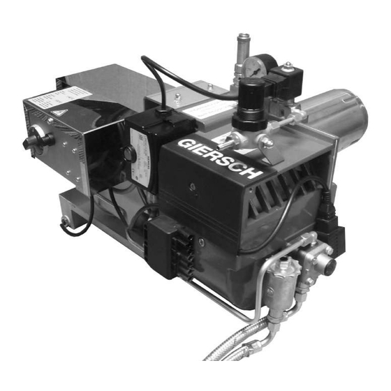
- Page 1 Technical Information • Installation Instructions Universal Oil Burner GU20 June 2021 edition In the interests of continuous product improvement, technical specifications are subject to change without prior notice.
-
Page 2: Table Of Contents
Contents General information ........................3 Checking scope of supply and electrical ratings ................ 3 Operating instructions ........................ 3 Instruction ..........................3 Maintenance and customer service ................... 3 Technical specifications ......................4 Functional description ........................ 4 Air/oil flow schematic........................4 Installing flange and burner......................5 Connecting to power supply....................... -
Page 3: General Information
2. Checking scope of supply and electrical ratings Before installing the GIERSCH universal oil burner please check the items supplied for completeness. Scope of supply: burner, mounting unit, separate operating instructions, technical information, flange seal. -
Page 4: Technical Specifications
Technical specifications 6. Technical specifications Burner type Technical specifications GU20 Output, fuel oil 33 - 52 Oil throughput, fuel oil kg/h 2.8 - 4.4 Output, rapeseed oil 27 - 40 Oil throughput, rapeseed oil kg/h 2.7 - 4.0 Compressor output Primary air connection 0.4-0.8... -
Page 5: Installing Flange And Burner
Install flange and burner 9.Install flange and burner Attach the burner flange and the seal to the heat generator. 10.Connect to power supply 7-pin • Connect the burner to the power supply using the supplied connector unit as indicated in the wiring diagram. -
Page 6: Oil Pump
Oil pump 12. Oil pump The oil pumps serve as delivery units, pumping oil into the burner tank. The atomisation of the oil is not dependent on the oil pressure. Oil pump: = feed = return = pressure pipe connection ... -
Page 7: Control Unit Lmo
Function testing the control unit 15. Function testing the control unit Testing the control unit for proper functioning Danger of fatal injury from electric shocks! Disconnect electrical cable from power supply before carrying out any work on live parts! Troubleshooting may only be carried out by authorised and trained personnel! Unlocking may only be carried out by an authorised specialist. - Page 8 Function testing the control unit Diagnostics of the cause of fault After lockout, the red fault signal lamp remains steady on. In that condition, the visual diagnostics of the cause of fault according to the error code table can be activated by pressing the lockout reset button for more than 3 seconds.
-
Page 9: Table Of Settings
If the oil level is too high, the float switch will switch off the burner. If the oil level is too low, the heating cartridge will become encrusted or damaged. Adjustment table for rapeseed oil Burner type GU20 Output in kW Oil throughput in kg/h Primary air in bar Secondary air 11.0... -
Page 10: Settings For Primary Airflow
Settings for primary airflow 17. Settings for primary airflow The primary airflow should be set using the pressure regulator (1) according to the required burner output. The information given in the diagram can be used as guide values. Higher-viscosity fuels require higher air pressures. 18. -
Page 11: Flue Connection
Flue connection 19. Flue connection The prerequisite for perfect operation of the furnace is a correctly dimensioned flue. Dimensioning is effected in accordance with DIN 4705 in consideration of DIN 18160 and based on the boiler and burner outputs. For operation on a sliding basis, provide flues as per DIN 18160 part, group 1. The flue gas mass flow of the total rated heat output must be factored into the calculation. -
Page 12: Wiring Diagram
SP_1-1066 E.04.2000 • G. 29.06.21... -
Page 13: Possible Errors
Troubleshooting 23. Troubleshooting Observation Cause Remedy Open the water drain cock on the burner tank, Oil not combustible due to sludge and / or water drain off sludge and water or use a higher-grade heating oil Refill tank with oil Oil tank empty Oil level in burner tank too high Correct the oil level by draining off oil by means... -
Page 14: Exploded View Drawing / Parts List
Exploded view drawing / spare parts list 24. Exploded view drawing / spare parts list... - Page 15 Exploded view drawing / spare parts list Position Designation Pack qty. Art. No. Burner pipe 47-90-22291 Mounting flange seal 47-50-26127 Diaphragm plate compl. with holder 47-90-22826 Delavan SNA nozzle 47-90-22804 Nozzle assembly compl. with ignition electrodes 47-90-22357 Ignition electrode 47-50-22381 Ignition cable pair 47-90-22278 Oil tank - nozzle assembly connecting tube...
-
Page 16: Burner Dimensions / Boiler Connecting Dimensions
Subject to change. Enertech GmbH • Brenner und Heizsysteme Adjutantenkamp 18 • D-58675 Hemer • Telephone 02372/965-0 • Telefax 02372/61240 Email: info@giersch.de • Internet: http://www.giersch.de...
Need help?
Do you have a question about the GU20 and is the answer not in the manual?
Questions and answers
HELLO YOU I HAVE A GIERSCH G 40-150 OIL BURNER AND I NEED THE ELECTRICAL MANUAL THE WIRING IN THE BASE OF THE TF 834 CONTROL HAS BEEN SHORTED. THANK YOU