
Related Manuals for Giersch G20


Summary of Contents for Giersch G20
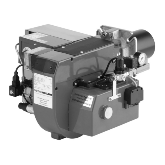
- Page 1 Technical Information • Installation Instructions Universal oil burner G July 2009 edition In the interests of continuous product improvement, technical specifications are subject to change without prior notice!
-
Page 2: Table Of Contents
Contents General information ........................3 Checking scope of supply and electrical ratings ................ 3 Operating instructions ........................ 3 Instruction ..........................3 Maintenance and customer service ................... 3 Technical specifications ......................4 Functional description ........................ 4 Air/oil flow schematic........................4 Installing flange and burner......................5 Connecting to power supply....................... -
Page 3: General Information
The design and degree of protection of the burner make it suitable for operation in en- closed rooms. 2. Checking scope of supply and electrical ratings Before installing the GIERSCH universal oil burner please check the items supplied for completeness. Scope of supply: burner, mounting unit, separate operating instructions, technical information, flange seal. -
Page 4: Technical Specifications
Technical specifications 6. Technical specifications Burner type Technical specifications G100 G150 G200 Output 32.0 Oil throughput kg/h 13.0 16.5 Compressor output 11.5 Primary air connection 0.4-0.8 0.4-0.8 0.45-0.65 0.5-0.8 0.4-0.8 0.4-0.8 Motor output Heating element 1100 Voltage 1/N/PE ~50 Hz 220 - 240 V Weight 12.5 7. -
Page 5: Installing Flange And Burner
Installing flange and burner 9.Installing flange and burner Attach the burner flange and the seal to the heat gen- erator. G55-100 G150-200 7-pin 10. Connecting to power supply • Connect the burner to the power supply using the supplied connector unit as indicated in the wiring diagram. -
Page 6: Oil Pump
Oil pump 12.Oil pump The oil pumps serve as delivery units, pumping oil into the burner tank. The atomisation of the oil is not dependent on the oil pressure. Oil pump SP25 for G20: = supply Π= return ... -
Page 7: Setting The Ignition Electrodes
Setting the ignition electrodes 14. Setting the ignition electrodes The ignition electrodes are preset. The specified dimensions (Fig.) are for checking purposes. G55/70/100 G150/200... -
Page 8: Control Unit
Function test of control box 15.Function test of control box Carry out the following checks after commissioning and each time after the burner has been serviced: • Restarting with a covered flame detector: the control unit must go into fault mode on expiration of the safety period. •... -
Page 9: Table Of Settings
Adjustment tables Measuring the photocurrent (MZ 770S only) To measure the photocurrent, disconnect the plug unit from the flame failure controller and install the Control unit bottom section pair of measuring cables* between the plug and socket unit. Both measuring connections should be 500µA 200µA connected to the measuring instrument. -
Page 10: Settings For Primary Airflow
Settings for primary airflow 17. Settings for primary airflow The primary airflow should be set using the pressure regula- tor (1) according to the required burner output. The informa- tion given in the diagram can be used as guide values. Higher-viscosity fuels require higher air pressures. -
Page 11: Flue Connection
Flue connection 19. Flue connection The prerequisite for perfect operation of the furnace is a correctly dimensioned flue. Dimensioning is effected in accordance with DIN 4705 in consideration of DIN 18160 and based on the boiler and burner outputs. For operation on a sliding basis, provide flues as per DIN 18160 part, group 1. The exhaust gas mass flow of the total rated heat output must be factored into the calculation. -
Page 12: Wiring Diagrams
Wiring diagrams 22.Wiring diagrams Boiler control Flame detector MZ770 = blue Heating coil 1100 W br = brown Ext. fuse ge = yellow Control thermostat gr = grey Ext. temperature control grü = green Ext. safety temperature limiter sw = black Ext. - Page 13 Wiring diagrams G55/70/100 Boiler control Flame detector MZ770 = blue Heating coil 1100 W br = brown Ext. fuse ge = yellow Control thermostat gr = grey Ext. temperature control grü = green Ext. safety temperature limiter sw = black Ext.
- Page 14 Wiring diagrams G150-200 Boiler control Flame detector MZ770 = blue Heating coil 1100 W br = brown Ext. fuse ge = yellow Control thermostat gr = grey Ext. temperature control grü = green Ext. safety temperature limiter sw = black Ext.
-
Page 15: Troubleshooting
Troubleshooting 23.Troubleshooting Observation Cause Remedy Open the water drain cock on the burner tank, Oil not combustible due to sludge and / or water drain off sludge and water or use a higher- grade heating oil Refill tank with oil Oil tank empty Correct the oil level by draining off oil by means Oil level in burner tank too high... -
Page 16: Explosion Drawing / Parts List
Explosion drawing / parts list 24. Explosion drawing / parts list GG20... - Page 17 Explosion drawing / parts list Position Designation Art. No. Burner pipe 47-90-22291 Mounting flange seal 47-50-26127 Diaphragm plate with holder compl. 47-90-22826 Delavan SNA nozzle 47-90-22804 Nozzle assembly compl. with Diaphragm plate/ignition electrodes 47-90-22357 Ignition electrode 47-50-22381 Ignition cables 47-90-22278 Oil-tank-nozzle assembly connecting tube 47-90-25370 Heating coil 1100W...
- Page 18 Explosion drawing / parts list GG55...
- Page 19 Explosion drawing / parts list Position Designation Art. No. Burner pipe 37-10-12112 Mounting flange seal 47-50-12094 Mounting flange compl. 47-30-12093 Diaphragm plate with holder compl. 41-30-20848 Delavan DA 2 nozzle 59-20-50449 Ignition electrodes (left + right) 47-90-26037 Nozzle assembly compl. 37-30-11391 Ignition cable 47-50-10564...
- Page 20 Explosion drawing / parts list G100...
- Page 21 Explosion drawing / parts list G100 Position Designation Art. No. Burner pipe 37-10-12112 Mounting flange seal 47-50-12094 Mounting flange compl. 47-30-12093 Diaphragm plate with holder compl. 41-30-20849 Delavan DA 2 nozzle 59-20-50449 Ignition electrodes (left + right) 47-90-26054 Nozzle assembly compl. 37-30-11391 Ignition cable 47-50-10564...
- Page 22 Explosion drawing / parts list G200...
- Page 23 Explosion drawing / parts list G200 Position Designation Art. No. Burner pipe 47-10-10774 Mounting flange seal 47-50-12094 Swivel flange, compl. preassembled 47-30-26181 Diaphragm plate with holder compl. 41-30-20850 Delavan DA 2 nozzle 59-20-50449 Ignition electrodes (left + right) 47-90-26511 Nozzle assembly compl. 37-30-12156 Ignition cable 47-50-12160...
-
Page 24: Burner Dimensions / Boiler Connecting Dimensions
Subject to alterations. Enertech GmbH • Brenner und Heizsysteme Adjutantenkamp 18 • D-58675 Hemer • Telephone +49 (0)2372/965-0 • Telefax +49 (0)2372/61240 E-mail: kontakt@giersch.de • Website: http://www.giersch.de...
Need help?
Do you have a question about the G20 and is the answer not in the manual?
Questions and answers