
Subscribe to Our Youtube Channel
Related Manuals for Giersch M3 Series


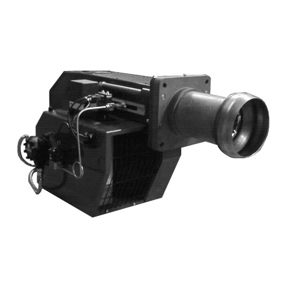
Summary of Contents for Giersch M3 Series
- Page 1 Technical Information • Installation Instructions Issued August 2007 Right reserved to effect technical changes in the interest of product improvement !
-
Page 2: Table Of Contents
Contents 1. General information ......................3 2. Standard Specifications......................3 3. Maintenance and customer service..................3 4. Operating Instructions ......................3 5. Instruction of operating personnel ..................3 6. Key for code designation ...................... 3 7. Technical specifications ......................4 8. -
Page 3: General Information
The burner must not be operated in rooms with high levels of air humidity (laundry rooms), dust or corro- sive vapours. 2. Standard Specifications Before installing the GIERSCH Series M3 oil burner, please check that al items included in the standard specifications are present. Items included in supply: burner, fixing unit, separate operating instructions, technical information leaflet, flange gasket, one 7-pin and one 4-pin connector (Wieland connector). -
Page 4: Technical Specifications
7. Technical data Burner type Technical data M3.12 M3.22 M3.32 Min. burner output in kW 1213 Max. burner output in kW 1494 2094 2503 Min. oil throughput kg/h Max. oil throughput kg/h Fuel oil Type EL, to DIN 51603 Method of operation 2-level, 2 nozzles Voltage 230 / 400 V - 50 Hz... -
Page 5: Installation Of Flange
9. Installation of flange The boiler connection plate must be prepared for the connection dimensions specified in "Boiler Connec- tion Dimensions". The flange gasket can be used as a marking template. First of all, loosen the size 17 nuts (2) and the cap nuts on the guide rods. -
Page 6: Inserting The Nozzles
12. Inserting the nozzles After removing the two M10 nuts (spanner size 17) the burner can be drawn back on the guide rods. It is now in the servicing position. Undo the screw and withdraw the flame ring forwards. Unscrew the plastic dust screw from the nozzle holder. When doing so, it is essential to ensure that the sealing face is not damaged. -
Page 7: Adjusting The Nozzle Assembly (Dimension "A")
14. Adjustment of the nozzle assembly (dimension "A“) The dimension "A" indicates the position of the nozzle assembly and flame ring in the burner blast tube taper. With the aid of the presetting table the burner can be set to the relevant output. In the case of boilers with a higher/lower furnace pressure, dimension "A"... -
Page 8: Oil Pump
Single-line system Nozzle 14 (gph) 20 (gph) 30 (gph) 45 (gph) .∅ mm H (m) L (m) L (m) L (m) L (m) L (m) L (m) L (m) L (m) L (m) L (m) L (m) L (m) L (m) L (m) L (m) -0.5... -
Page 9: Electrical Connections
Remove the return pipe and connection fitting. Uns- crew the bypass plug from the return pipe connec- tion and seal off with a plug. The intake volume of the pump is then the same as the nozzle flow rate. 1 = feed line 2 = return line 3 = nozzle output 4 = pressure adjuster... -
Page 10: Air Flap Positioning Motor
Upon completion of the connection work check the wiring and briefly actuate the motor contactor with an electrician's insulated screwdriver to check the direc- tion of rotation of the burner motor (not on the star-del- ta version, though). The direction of rotation is correct if the fan turns to- ward the boiler (see the arrow on the motor flange). -
Page 11: Automatic Oil Firing Control Devices
Please note the following when adjusting the switch cams: – Do not set cam position for ST1 higher than ST2. – Set cam position MV2 roughly 10°-20° above cam position ST1. – Check cam position for MV2 after correcting cam position for ST1. –... -
Page 12: Start-Up
23. Start-up • Screw in oil pressure gauge for measuring pump pressure. • Preset the burner in accordance with the nozzle selection table on page 13 to the appropriate boiler out- put. – Nozzle size – Dimension "A“ – Air valve position for level 1/level 2 •... -
Page 13: Control Device Landis&Gyr Lal 1.25
25. Control device Landis&Gyr LAL 1.25 In the event of faults the programming mechanism always stops. The symbol above the indicator's read- off mark identifies the type of fault: No start, e.g., because the CLOSED signal from the end changeover switch «Z» (or auxiliary switch «M») is missing at terminal 8 or because contact has not been made at terminals 4 and 5. -
Page 14: Nozzle Selection Diagram
27. Nozzle selection diagram If the desired output deviates from the values specified in the tables, the nozzle size and pump pressure can be determined with the aid of the following diagram. Öl- durch- Brenner- Düsen- Burner output Oil throughput satz Nozzle size größe... -
Page 15: Circuit Diagram M3
28. Circuit diagram M3 Switchboard Flame failure controller Ext. fuses 16 AT Protective motor switch Ext. ON lamp, level 1 Ext. operating lamp 2nd level Ext. fault message lamp Mains voltage operating lamp Motor contactor Burner motor Ext. time meter level 1 Ext. -
Page 16: Circuit Diagram M3 With Star-Delta Circuit
29. Circuit diagram M3 with star-delta circuit Switchboard Flame failure controller Ext. fuses 16 AT Protective motor switch H11 Ext. ON lamp, level 1 H12 Ext. operating lamp level 2 H13 Ext. fault message lamp Mains voltage operating lamp Motor contactor Burner motor P11 Ext. -
Page 17: Exploded Illustration M3
30. Exploded illustration M3... -
Page 18: Spare Parts List
31. Spare parts list Item Designation M3.12-Z-L M3.22-Z-L M3.32-Z-L Burner pipe 46-10-12726 46-10-12970 46-10-12971 Burner pipe with 100 mm elongation 47-10-21934 46-10-21935 46-10-12991 Flange gasket 46-10-12738 47-10-12911 47-10-12911 Mounting flange with guide rods 46-30-21871 47-30-12909 47-30-12909 Diaphragm plate with ignition electrode compl. 47-30-22618 47-30-22619 47-30-22619... - Page 19 E. 30.05.01 • G.06.08.07...
-
Page 20: Working Ranges
M3.32 34. Declaration of conformity We declare that the Giersch M3 oil blower burner meets the basic requirements of the following directives: • "Low Voltage Directive" according to 73/23/EEC in conjunction with DIN VDE 0700 Part 1 / Ed. 04.88 and DIN VDE 0722 / Ed.
Need help?
Do you have a question about the M3 Series and is the answer not in the manual?
Questions and answers