
Related Manuals for Giersch GG35


Summary of Contents for Giersch GG35
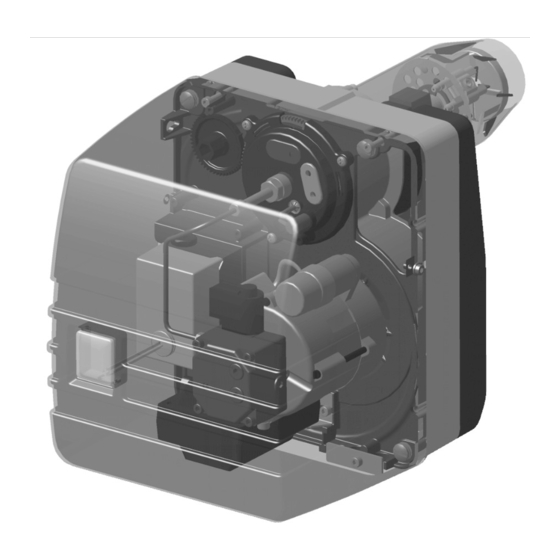
- Page 1 Brenner und Heizsysteme Technical Information • Installation Instructions GG35/55/80 1IIKA .A>HK=HO Right reserved to effect techn. modifications in the interest of product improvement !
-
Page 2: Table Of Contents
Servicing is required annually. We recommend that you conclude a service contract with an approved spe- cialized company. 3. Conformity declaration We declare that the Giersch GG35/55/80 oil blow burner meets the basic requirements of the following direc- tives: • "Low-Voltage Directives" in compliance with 73/23/ EEC in conjunction with DIN VDE 0700 part 1/ issue 04.88 and DIN VDE 0722/issue 04.83... -
Page 3: Technical Specifications
4. Technical specifications GG 35-V GG 35 GG 55-V GG 55 GG 80 Burner output in kg/h 1.00-3.35 1.20-3.35 1.00-5.05 1.20-5.05 3.35-6.75 in kW 12-40 14-40 12-60 14-60 40-80 Recommended boiler output in kW 13,5-38 16,5-38 11-57 13-57 37-73.5 Voltage 230 V/ 50 Hz Power consumption in W (max.) -
Page 4: Oil Pump
7. Oil pump The pump pressure must be adjusted to suit the relevant output (see Table of settings on p. 14). The specified pump pressures are only guide values and may deviate depending on plant conditions. To do so: • Unscrew and remove the pressure measuring connection •... -
Page 5: Service Position
9. Service position -Release the quick-action fasteners -Pull the mounting plate out of the housing -Hook the mounting plate by its retaining straps onto the two top screws (service position). To reassemble insert the mounting plate into the housing and secure with the quick-action fasteners. -
Page 6: Adjustment Of The Air Volume Dimension "B" And Dimension "A
12. Adjustment of the air volume dimension "B" and dimension "A" Dimension "B" The scale serves as an orientation aid for easier adjustment of the air volume. The air volume is altered by means of a hexagon spanner (size 17) depending on the output in com- Zero mark Scale pliance with the table of settings. -
Page 7: Operability Check
13.Operability check of the flame monitoring control device Carry out the following checks after commissioning and each time after the burner has been serviced: 1 Restart with covered up flame failure controller: The control device must switch to fault upon expiry of the safety period. 2. -
Page 8: Oil Preheating
Set the measuring instrument to ampere metering for DC, measuring range up to approx. 200 µA ! Useful measuring accessory Digital measuring instrument art. no. 59-20-50263 14.Oil preheating (GG35/55-V only) The oil preheating is upline from the burner program sequence and remains in operation until the oil burner is switched off by the control thermostat. - Page 9 The following functions can be displayed: Function Display Momentary consump- 0000.00 tion ◊ Oil volume 0000.00 (resettable) Oil volume 000000 (total) Total operating hours 000000 Number of 000000 burner startups Reduced throughput (see Service function) Service Resetting the oil volume counter Resetting of the oil volume counter can be effected in the mode ◊.: =>...
-
Page 10: Boiler/Burner Conditioning
= green Main heating switch = black Automatic firing unit Satronic TF830/832 or LOA 24 = red for hot air generators with DKW 972 f. GG35/55/80 = white for hot air generators with DKW 976 f. GG35/55-V Oil control (optional) -
Page 11: Circuit Diagram
19.Circuit diagram Boiler control Burner GG35/55/80 with TF830/832 Boiler control Burner GG35/55-V with TF830/832... - Page 12 Boiler control Burner GG35/55/80 with LOA 24 Boiler control Burner GG35/55-V with LOA 24...
-
Page 13: Troubleshooting
20.Troubleshooting Defect determined Cause Remedy Fuse defective Replace Safety thermostat disabled Enable Controller temperature setting exceeded Once temperature dropped, repeat start attempt Burner motor not opera- Control device defective Replace ting Motor defective Replace Oil preheater: heater or enabling thermostat Replace defective Motor–pump coupling defective... -
Page 14: Table Of Settings
19-21 2.0-2.2 18.5 17.0 0.45 19.5-20.5 26-28 2.0-2.2 20.5 18.5 0.50 20-21 30-33 2.1-2.3 24.5 22.5 0.55 22-23 37-40 2.2-2.4 GG35-V 27.0 25.0 0.60 23-24 42-45 2.2-2.4 31.5 29.0 0.65 24-25 53-57 2.3-2.5 34.5 32.0 0.75 25-26 67-72 2.3-2.6 38.0 35.0... -
Page 15: Burner Cross-Section And Spare Parts List
47-20-22085 Retarding disc with retainer and twin electrode 47-30-22035 47-30-22086 Twin electrode 47-20-22087 Nozzle stock cpl. 47-20-22062 Nozzle stock cpl. with oil preheater and cable (GG35/55-V) 47-20-21979 Ignition cable, length 600 mm 47-50-10385 Sliding flange 31-20-10103 Flange gasket 31-50-10104 Air regulation sleeve... -
Page 16: Burner Overall Dimensions / Boiler Connection Dimensions
Right reserved to effect modifications. GIERSCH GmbH • Brenner und Heizsysteme Postfach 3063 • D-58662 Hemer • Telephone 02372/965-0 • Fax 02372/61240 E-mail: kontakt@giersch.de • Internet: http://www.giersch.de...
Need help?
Do you have a question about the GG35 and is the answer not in the manual?
Questions and answers