Table of Contents
Advertisement
Quick Links
Advertisement
Table of Contents

Related Manuals for Advantech SOM-7533


Summary of Contents for Advantech SOM-7533
- Page 1 User Manual SOM-7533 CPU Computer on Module...
- Page 2 No part of this manual may be reproduced, copied, translated, or transmitted in any form or by any means without the prior written permission of Advantech Co., Ltd. The information provided in this manual is intended to be accurate and reliable.
- Page 3 This product has passed the CE test for environmental specifications when shielded cables are used for external wiring. We recommend the use of shielded cables. This type of cable is available from Advantech. Please contact your local supplier for ordering information.
- Page 4 Document Feedback To assist us with improving this manual, we welcome all comments and constructive criticism. Please send all feedback in writing to support@advantech.com. Safety Precautions - Static Electricity Follow these simple precautions to protect yourself from harm and the products from damage.
- Page 5 In accordance with IEC 704-1:1982 specifications, the sound pressure level at the operator’s position should not exceed 70 dB (A). DISCLAIMER: This set of instructions is given according to IEC 704-1. Advantech disclaims all responsibility for the accuracy of any statements contained herein.
- Page 6 SOM-7533 User Manual...
-
Page 7: Table Of Contents
Power Management..............9 1.3.10 Environment................10 1.3.11 MTBF ..................10 1.3.12 OS Support ................. 10 1.3.13 Advantech iManager ..............10 1.3.14 Power Consumption..............11 Table 1.9: Power Consumption Table (Watts)......11 1.3.15 Selection Guide w/ P/N ............... 11 Table 1.10:Selection Guide w/ P/N..........11 1.3.16 Packing list.................. - Page 8 Figure 3.36Security Configuration ..........55 Figure 3.37HD Audio Subsystem Configuration Settings... 56 Figure 3.38SerialIo Configuration..........57 Figure 3.39Serial IO I2C2 Settings..........58 Figure 3.40Serial IO I2C4 Settings..........59 Figure 3.41Serial IO UART0 Settings......... 60 Figure 3.42SCS Configuration............ 61 SOM-7533 User Manual viii...
- Page 9 Other OS..................68 Advantech iManager ................69 Appendix A Pin Assignment .........71 SOM-7533 Pin Assignment..............72 Table A.1: SOM-7533 Rows A, B ..........72 Appendix B Watchdog Timer ........77 Programming the Watchdog Timer ............78 Table B.1: Programming the Watchdog Timer......78...
- Page 10 SOM-7533 User Manual...
-
Page 11: Chapter 1 General Information
Chapter General Information This chapter gives background information on the SOM-7533 CPU Computer on Module. Sections include: Introduction Functional Block Diagram Product Specifications... -
Page 12: Introduction
Introduction SOM-7533 is a COM Express Compact module with pin-out Type 10 that fully com- plies with the PICMG (PCI Industrial Computer Manufactures Group) COM R3.1 specifications. The CPU module utilizes Intel® i3 & N-series and Atom® x7000E Series Processors (formally called Alder Lake N) in a mini-sized 55x84mm COM Express form factor, featuring a 15-watt thermal design power (TDP) rating. - Page 13 Serial Presence Detect – refers to serial EEPROM on DRAM that has DRAM Module configuration information Trusted Platform Module, chip to enhance the security features of a com- puter system UEFI Unified Extensible Firmware Interface Watchdog Timer SOM-7533 User Manual...
-
Page 14: Functional Block Diagram
Functional Block Diagram SOM-7533 User Manual... -
Page 15: Product Specifications
General Purpose I/O (GPIO) 8 Watchdog Timer Output Speaker Out External BIOS ROM Support 1 Power Button Support Power Good VCC_5V_SBY Contacts Sleep Thermal Protection Lid Input Battery Low Alarm Suspend/Wake Signals Fan PWM/Tachometer Trusted Platform Modules USB 3.0 SOM-7533 User Manual... -
Page 16: Processor System
PCI Express x1: Supported by default: 4 x PCIe x1 compliant with PCIe Gen3 (8.0 GT/s) specifications, configurable to PCIe x4 or PCIe x2. Several configurable combi- nations may need BIOS modification. Please contact the Advantech sales or FAE for more details. -
Page 17: Serial Bus
1.3.8.3 USB 3.2 / USB 2.0 SOM-7533 supports 2 x USB 3.2 Gen 2 (10 Gbps) and 8 x USB 2.0 (480 Mbps) which are reverse compatible to USB 1.x. For USB 3.2, the product supports LPM (U0, U1, U2, and U3) for power efficiency. - Page 18 SPI_CS0# to Carrier Board, SPI_CS1# to Module SPI_CS0# to Module, SPI_CS1# to Carrier Board Note: If system COMS is cleared, Advantech strongly suggests going to the BIOS setup menu and loading default settings on the first bootup. SOM-7533 User Manual...
-
Page 19: Power Management
Wake-on-LAN(WOL): Wake to S0 from S3/S4/S5 USB Wake: Wake to S0 from S3 PCIe Device Wake: depends on user inquiry and may need customized BIOS LPC Wake: depends on user inquiry and may need customized BIOS SOM-7533 User Manual... -
Page 20: Environment
1.3.12 OS Support The mission of Advantech Embedded Software Services is to "Enhance quality of life with Advantech platforms and Microsoft Windows Embedded technology." We enable Windows Embedded software products on Advantech platforms to more effectively support the embedded computing community. -
Page 21: Power Consumption
Idle mode: DUT power management off and not running any programs. OS: Windows 10 Enterprise 1.3.14.1 Performance To compare performance or benchmark data with other modules, please refer to the “Advantech COM Performance & Power Consumption Table.” 1.3.15 Selection Guide w/ P/N Table 1.10: Selection Guide w/ P/N Max. -
Page 22: Packing List
COMe Devel. Board COMe R3.1 Type6 pin-out (LVDS) 0 ~ 60°C SOM-DB5830A-00A3 COMe Devel. Board COMe R3.1 Type6 pin-out (eDP) 0 ~ 60°C Note: SOM-7533 needs to have the middle board EA00 assembly. Then the pin out will map to Type 10 with SOM-DB5830. 1.3.18 Optional Accessory Table 1.13: Optional Accessory... -
Page 23: Chapter 2 Mechanical Information
Chapter Mechanical Information This chapter gives mechanical information for the SOM-7533 CPU Computer on Module. Sections include: Board Information Mechanical Diagrams Assembly Diagrams... -
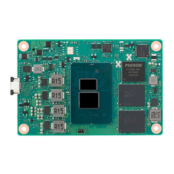
Page 24: Board Information
Board Information The figures below indicate the main chips on the SOM-7533 Computer-on-Module. Please be aware of these positions when designing a customer’s carrier board to avoid mechanical interference and thermal solution contacts for best thermal dissipa- tion performance. Intel® i3 & N-series, Atom®... -
Page 25: Mechanical Diagrams
Mechanical Diagrams For more details on 2D/3D models, please find them on the Advantech COM support service website: http://com.advantech.com. Figure 2.3 Board Mechanical Diagram – Front Figure 2.4 Board Mechanical Diagram – Rear Figure 2.5 Board Mechanical Diagram – Side... -
Page 26: Assembly Diagrams
These figures demonstrate the order of assembly for attaching the thermal module and COM module to the carrier board. Figure 2.6 Assembly Diagram There are 4 reserved screw holes for SOM-7533 to be pre-assembled with a heat spreader. SOM-7533 User Manual... -
Page 27: Assembly Diagram
Assembly Diagram Please consider the CPU and chip height tolerance when designing your thermal solution. Figure 2.7 CPU Height and Tolerance SOM-7533 User Manual... - Page 28 SOM-7533 User Manual...
-
Page 29: Chapter 3 Ami Bios
Chapter AMI BIOS This chapter provides BIOS setup information for the SOM-7533 CPU Computer on Module. Sections include: Introduction Entering Setup Hot/Operation Keys Exiting the BIOS Setup Utility... -
Page 30: Introduction
This information is stored in flash ROM so it retains the setup information when the power is turned off. Entering Setup Turn on the computer and then press <DEL> or <ESC> to enter the Setup menu. SOM-7533 User Manual... -
Page 31: Main Setup
System Date using the <Arrow> keys. Enter new values through the keyboard. Press the <Tab> key or the <Arrow> keys to move between fields. The date must be entered in MM/DD/YY format. The time must be entered in HH:MM:SS format. SOM-7533 User Manual... -
Page 32: Advanced Bios Features Setup
Advanced BIOS Features Setup Select the Advanced tab from the SOM-7533 setup screen to enter the Advanced BIOS Setup screen. Users can select any item in the left frame of the screen, such as CPU Configuration, to go to the sub-menu for that item. Users can display an Advanced BIOS Setup option by highlighting it using the <Arrow>... -
Page 33: Cpu Configuration
Enable/Disable CPU Flex Ratio programming. Active Efficient-cores Numbers of E-cores to enable in each processor package. Note: The number of Cores and E-cores are looked at together. When both are {0,0}, Pcode will enable all cores. SOM-7533 User Manual... -
Page 34: Power & Performance
3.4.2 Power & Performance Figure 3.5 Power & Performance CPU - Power Management Control CPU - Power Management Control Options. GT - Power Management Control GT - Power Management Control Options. SOM-7533 User Manual... - Page 35 Enable/Disable processor Turbo Mode (requires EMTTM enabled too). AUTO means enabled. Config TDP Configurations Configurable Processor Base Power (cTDP) Configurations. C states Enable/Disable CPU Power Management. Allows CPU to go to C states when it is not 100% utilized. SOM-7533 User Manual...
- Page 36 Power Limit2 in milliwatts. BIOS will round to the nearest 1/8W when program- ming. 0=no custom override. For 12.50W, enter 12500. The processor applies control policies such that the package power does not exceed this limit. SOM-7533 User Manual...
- Page 37 Custom value for the Turbo Activation Ratio. It needs to be configured with valid values from LFM to Max Turbo. 0 means it does not use a custom value. 3.4.2.2 GT - Power Management Control Figure 3.8 GT - Power Management Control SOM-7533 User Manual...
-
Page 38: Pch-Fw Configuration
When Disabled, ME will be put into ME Temporarily Disabled Mode. ME Unconfig on RTC Clear When Disabled, ME will not be unconfigured on RTC clear. Firmware Update Configuration Configure Management Engine Technology Parameters. SOM-7533 User Manual... - Page 39 3.4.3.1 Firmware Update Configuration Figure 3.10 Firmware Update Configuration Me FW Image Re-Flash Enable/Disable the Me FW Image Re-Flash function. FW Update Enable/Disable the ME FW Update function. SOM-7533 User Manual...
-
Page 40: Trusted Computing
TPM 1.2 will restrict support to TPM 1.2 devices. TPM 2.0 will restrict support to TPM 2.0 devices. Auto will support both with the default set to TPM 2.0 devices if not found. TPM 1.2 devices will be enumerated. SOM-7533 User Manual... -
Page 41: Acpi Settings
Enable or Disable the System’s ability to Hibernate (OS/S4 Sleep State). This option may be not effective with some OS. ACPI Sleep State Select the highest ACPI sleep state the system will enter when the SUSPEND button is pressed. SOM-7533 User Manual... -
Page 42: Embedded Controller
Set Parameters of Serial Port 2 (COMB). Hardware Monitor Monitor hardware status. CAN0 Control Enable/Disable CAN0 controller on RDC-IS200. I2C0 Control Enable/Disable I2C0 controller on RDC-IS200. SMBus0 Control Enable/Disable SMBus0 controller on RDC-IS200. SOM-7533 User Manual... - Page 43 3.4.6.1 Serial Port 1 Configuration Figure 3.14 Serial Port 1 Configuration Serial Port Enable or Disable Serial Port (COM). Change Settings Select an optimal setting for a Super IO Device. SOM-7533 User Manual...
- Page 44 3.4.6.2 Serial Port 2 Configuration Figure 3.15 Serial Port 2 Configuration Serial Port Enable or Disable Serial Port (COM). Change Settings Select optimal settings for a Super IO Device. SOM-7533 User Manual...
- Page 45 3.4.6.3 Hardware Monitor Figure 3.16 Hardware Monitor SOM-7533 User Manual...
-
Page 46: Serial Port Console Redirection
Serial Port Console Redirection Figure 3.17 Serial Port console Redirection COM1 Console Redirection Console Redirection Enable or Disable. Legacy Console Redirection Settings Legacy Console Redirection Settings. Console Redirection EMS Console Redirection Enable or Disable. SOM-7533 User Manual... -
Page 47: Usb Configuration
Maximum time the device will take before it properly reports itself to the Host Controller. 'Auto' uses the default value: for a Root port it is 100 ms, for a Hub port the delay is taken from the Hub descriptor. SOM-7533 User Manual... -
Page 48: Oem Configuration
3.4.9 OEM Configuration Figure 3.19 OEM Configuration SATA_LED/SPKR Pin Control Select GPP_B14 pin function to Serial ATA LED or Speaker Output. Hybrid: SPKR in pre-boot, SATA LED in runtime. SOM-7533 User Manual... -
Page 49: Network Stack Configuration
3.4.10 Network Stack Configuration Figure 3.20 Network Stack Configuration Network Stack Enable/Disable UEFI Network Stack. SOM-7533 User Manual... -
Page 50: Compatibility Support Module Configuration
3.4.11 Compatibility Support Module Configuration Figure 3.21 Compatibility Support Module Configuration CSM Support Enable/Disable CSM Support. SOM-7533 User Manual... -
Page 51: Chipset Setup
Chipset Setup Figure 3.22 Chipset Setup System Agent (SA) Configuration System Agent Parameters. PCH-I0 Configuration PCH parameters. SOM-7533 User Manual... -
Page 52: System Agent (Sa) Configuration
Memory Configuration Parameters. Graphics Configuration Graphics Configuration. VT-d VT-d capability. Above 4GB MMIO BIOS assignment Enable/Disable above 4GB memory mapped IO BIOS assignment. This is enabled automatically when aperture size is set to 2048MB. SOM-7533 User Manual... - Page 53 3.5.1.1 Memory Configuration Figure 3.24 Memory Configuration SOM-7533 User Manual...
- Page 54 Select the GTT size. Aperture Size Select the aperture size. Note: Above 4GB MMIO BIOS assignment is automat- ically enabled when selecting 2048MB aperture. To use this feature, please dis- able CSM support. LCD Control LCD Control. SOM-7533 User Manual...
- Page 55 Figure 3.26 LCD Control – LCD Panel Type Select the LCD panel used by the Internal Graphics Device by selecting the appropriate setup item. Panel Scaling – Select the LCD panel scaling option used by the Internal Graphics Device. SOM-7533 User Manual...
-
Page 56: Pch-Io Configuration
SATA device option settings. USB Configuration USB Configuration settings. Security Configuration Security Configuration settings. HD Audio Configuration HD audio subsystem configuration settings. SerialIo Configuration SerialIo configuration settings. SCS Configuration Storage and Communication Subsystem (SCS) Configuration. SOM-7533 User Manual... - Page 57 PCI Express Root Port Settings. PCI Express Root Port 7 PCI Express Root Port Settings. PCI Express Root Port 9 PCI Express Root Port Settings. PCI Express Root Port 10 PCI Express Root Port Settings. SOM-7533 User Manual...
- Page 58 ASPM Set the ASPM Level: Force L0s – Force all links to L0s State AUTO – BIOS auto configure DISABLE – Disables ASPM. – Hot Plug PCI Express Hot Plug Enable/Disable. – PCIe Speed Configure PCIe Speed. SOM-7533 User Manual...
- Page 59 ASPM Set the ASPM Level: Force L0s – Force all links to L0s State AUTO – BIOS auto configure DISABLE – Disables ASPM. – Hot Plug PCI Express Hot Plug Enable/Disable. – PCIe Speed Configure PCIe Speed. SOM-7533 User Manual...
- Page 60 ASPM Set the ASPM Level: Force L0s – Force all links to L0s State AUTO – BIOS auto configure DISABLE – Disables ASPM. – Hot Plug PCI Express Hot Plug Enable/Disable. – PCIe Speed Configure PCIe Speed. SOM-7533 User Manual...
- Page 61 ASPM Set the ASPM Level: Force L0s – Force all links to L0s State AUTO – BIOS auto configure DISABLE – Disables ASPM. – Hot Plug PCI Express Hot Plug Enable/Disable. – PCIe Speed Configure PCIe Speed. SOM-7533 User Manual...
- Page 62 ASPM Set the ASPM Level: Force L0s – Force all links to L0s State AUTO – BIOS auto configure DISABLE – Disables ASPM. – Hot Plug PCI Express Hot Plug Enable/Disable. – PCIe Speed Configure PCIe Speed. SOM-7533 User Manual...
- Page 63 SATA Controller(s) Enable/Disable an SATA Device. SATA Controller Speed Indicates the maximum speed the SATA controller can support. Port 0 Enable or Disable the SATA Port. Port 1 Enable or Disable the SATA Port. SOM-7533 User Manual...
- Page 64 3.5.2.3 USB Configuration Figure 3.35 USB Configuration xDCI Support Enable/Disable xDCI (USB OTG Device). USB Port Disable Override Selectively Enable/Disable the corresponding USB port from reporting a Device Connection to the controller. SOM-7533 User Manual...
- Page 65 Enable/Disable the PCH BIOS Lock Enable feature. It is required to be enabled to ensure SMM protection of flash. Force unlock on all GPIO pads If Enabled, BIOS will force all GPIO pads to be in the unlocked state. SOM-7533 User Manual...
- Page 66 3.5.2.5 HD Audio Subsystem Configuration Settings Figure 3.37 HD Audio Subsystem Configuration Settings HD Audio Control Detection of the HD-Audio device. Disabled=HDA will be unconditionally disabled. Enabled=HDA will be unconditionally enabled. SOM-7533 User Manual...
- Page 67 0 in a multifunction device. The following devices depend on each other: I2C0 and I2C1,2,3 UART0 and UART1,SPI0,1 UART2 and I2C4,5 UART 0 (00:30:00) cannot be disabled when: 1. Child device is enabled like CNVi Bluetooth (\_SB.PC00.UA00.BTH0) SOM-7533 User Manual...
- Page 68 SerialIO timing parameters Enables additional timing parameters for all SerialIo controllers. Defaults can be changed in each controller setting. A platform restart is required to apply changes. Serial IO I2C2 Settings Figure 3.39 Serial IO I2C2 Settings SOM-7533 User Manual...
- Page 69 Serial IO I2C4 Settings Figure 3.40 Serial IO I2C4 Settings SOM-7533 User Manual...
- Page 70 Disabled: No _PS0 _PS3 support, device is left in D0, after initialization Enabled: _PS0 _PS3 supports getting the device out of reset Auto: _PS0 and _PS3 detection through ACPI if the device was initialized prior to first PG. If it was used, (DBG2) PG is disabled. SOM-7533 User Manual...
- Page 71 Enable HS400 software tuning Software tuning should improve eMMC HS400 stability at the expense of boot time. Driver Strength Sets I/O driver strength. UFS 2.0 Controller 1 Enable or Disable the UFS 2.0 Controller. SOM-7533 User Manual...
-
Page 72: Security Chipset
Security Chipset Figure 3.43 Security Chipset Administrator Password Set Setup Administrator Password. User Password Set User Password. Secure Boot Secure Boot Configuration. SOM-7533 User Manual... -
Page 73: Secure Boot
System is in User mode. The mode change requires a plat- form reset. Secure Boot Mode Secure Boot mode options: Standard or Custom. In Custom mode, Secure Boot Policy variables can be configured by a physi- cally present user without full authentication. SOM-7533 User Manual... -
Page 74: Boot Setup
Number of seconds to wait for the setup activation key. 65535(0xFFFF) means indefinite waiting. Bootup NumLock State Select the keyboard NumLock state. Quiet Boot Enable or Disable the Quiet Boot option. Boot Option #1 Sets the system boot order. SOM-7533 User Manual... -
Page 75: Save & Exit
Restore/Load default values for all the setup options. Save as User Defaults Save the changes done so far as User Defaults. Restore User Defaults Restore the user defaults to all the setup options. Boot Override SOM-7533 User Manual... - Page 76 SOM-7533 User Manual...
-
Page 77: S/W Introduction & Installation
Chapter S/W Introduction & Installation S/W Introduction Driver Installation Advantech iManager... -
Page 78: S/W Introduction
S/W Introduction The mission of Advantech Embedded Software Services is to "Enhance quality of life with Advantech platforms and Microsoft Windows embedded technology." We enable Windows Embedded software products on Advantech platforms to more effectively support the embedded computing community. Customers are freed from the hassle of dealing with multiple vendors (Hardware suppliers, System integrators, Embedded OS distributor) for projects. -
Page 79: Advantech Imanager
Advantech iManager Advantech’s platforms come equipped with iManager, a micro-controller that provides embedded features for system integrators. Embedded features have been moved from the OS/BIOS level to the board level to increase reliability and simplify integra- tion. iManager runs whether the operating system is running or not; it can count the boot times and running hours of the device, monitor device health, and provide an advanced watchdog to handle errors just as they happen. - Page 80 SOM-7533 User Manual...
-
Page 81: Appendix A Pin Assignment
Appendix Pin Assignment This appendix gives you the infor- mation about the hardware pin assignments for the SOM-7533 CPU System on Module. Sections include: SOM-7533 Type 10 Pin Assign- ment... -
Page 82: Som-7533 Pin Assignment
This section shows the SOM-7533 pin assignment on the COM Express connector, which is compliant with COMR.0 R3.1 Type 10 pin-out definitions. For more details about how to use these pins and for design reference, please contact Advantech for a design guide, checklist, reference schematic, and other hardware/software support. - Page 83 Table A.1: SOM-7533 Rows A, B USB4+ USB5+ GND (FIXED) GND (FIXED) USB2- USB3- USB2+ USB3+ USB_2_3_OC# USB_0_1_OC# USB0- USB1- USB0+ USB1+ VCC_RTC ESPI_EN# CB_RSMRST# LAN0_SDP0 SYS_RESET# LPC_SERIRQ CB_RESET#(PLTRST#) GND (FIXED) GND (FIXED) RSVD RSVD RSVD RSVD GPI0 GPO1 GP_SPI_CS#...
- Page 84 Table A.1: SOM-7533 Rows A, B RSVD VCC_5V_SBY eDP_HPD VCC_5V_SBY PCIE0_CK_REF+ BIOS_DIS1# PCIE0_CK_REF- DDI0_HPD GND (FIXED) GND (FIXED) SPI_POWER SPI_MISO GPO0 SPI_CLK SPI_MOSI DDI0_DDC_AUX_SEL TPM_PP TYPE10# SPI_CS# SER0_TX DDI0_CTRLCLK_AUX+ SER0_RX DDI0_CTRLDATA_AUX- A100 GND (FIXED) B100 GND (FIXED) A101 SER1_TX B101...
- Page 85 B18 could be an optional pin reserved for ESPI_RESET#. Please contact FAE for details. B79 could be an optional pin reserved for eDP_BKLT_EN. Please contact FAE for details. B83 could be an optional pin reserved for eDP_BKLT_CTRL. Please contact FAE for details. SOM-7533 User Manual...
- Page 86 SOM-7533 User Manual...
-
Page 87: Appendix B Watchdog Timer
Appendix Watchdog Timer This appendix gives you informa- tion about programming the watchdog timer on the SOM-7533 CPU System on Module. Sections include: Watchdog Timer Programming... -
Page 88: Programming The Watchdog Timer
BIOS, and then sets it to EC. Only Win10 supports it. In other OS, it will still use the IRQ number from the BIOS settings as usual. For details, please refer to iManager and the Software API User Manual. SOM-7533 User Manual... -
Page 89: Appendix C Programming Gpio
Appendix Programming GPIO This appendix illustrates the Gen- eral Purpose Input and Output pin settings. Sections include: GPIO Register... -
Page 90: Gpio Register
Table C.1: GPIO Register GPIO Byte Mapping H/W Pin Name BIT0 GPI0 BIT1 GPI1 BIT2 GPI2 BIT3 GPI3 BIT4 GPO0 BIT5 GPO1 BIT6 GPO2 BIT7 GPO4 For details, please refer to iManager and the Software API User Manual. SOM-7533 User Manual... -
Page 91: Appendix D System Assignments
Appendix System Assignments This appendix gives you informa- tion about system resource allo- cation on the SOM-7533 CPU System on Module. Sections include: System I/O Ports DMA Channel Assignments Interrupt Assignments 1 MB Memory Map... -
Page 92: System I/O Ports
Programmable interrupt controller 0x00000034-0x00000035 Programmable interrupt controller 0x00000038-0x00000039 Programmable interrupt controller 0x0000003C-0x0000003D Programmable interrupt controller 0x000000A0-0x000000A1 Programmable interrupt controller 0x000000A4-0x000000A5 Programmable interrupt controller 0x000000A8-0x000000A9 Programmable interrupt controller 0x000000AC-0x000000AD Programmable interrupt controller 0x000000B0-0x000000B1 Programmable interrupt controller 0x000000B4-0x000000B5 Programmable interrupt controller SOM-7533 User Manual... -
Page 93: Interrupt Assignments
IRQ 4294967291 Intel® UHD Graphics IRQ 4294967292 Standard SATA AHCI Controller IRQ 4294967293 PCI Express Root Port #1 - 54B8 IRQ 4294967294 PCI Express Root Port #7 - 54BE IRQ 55-204 Microsoft ACPI-Compliant System IRQ 6 Motherboard resources SOM-7533 User Manual... -
Page 94: 1St Mb Memory Map
Intel® Serial IO GPIO Host Controller - INTC1057 0xFD690000-0xFD69FFFF Intel® Serial IO GPIO Host Controller - INTC1057 0x132A000-0x132AFFF Intel SD Host Controller 0xFFCF8000-0xFFCF8FFF Intel® Serial IO I2C Host Controller - 54EA 0x1310000-0x1317FFF Performance Monitor 0xFE010000-0xFE010FFF SPI (flash) Controller - 54A4 SOM-7533 User Manual... - Page 95 SOM-7533 User Manual...
- Page 96 No part of this publication may be reproduced in any form or by any means, such as electronically, by photocopying, recording, or otherwise, without prior written permission from the publisher. All brand and product names are trademarks or registered trademarks of their respective companies. © Advantech Co., Ltd. 2024...
Need help?
Do you have a question about the SOM-7533 and is the answer not in the manual?
Questions and answers