Table of Contents
Advertisement
Quick Links
Advertisement
Table of Contents

Related Manuals for Advantech SOM-7532


Summary of Contents for Advantech SOM-7532
- Page 1 User Manual SOM-7532 CPU Computer on Module...
- Page 2 No part of this manual may be reproduced, copied, translated, or transmitted in any form or by any means without the prior written permission of Advantech Co., Ltd. The information provided in this manual is intended to be accurate and reliable.
- Page 3 This product has passed the CE test for environmental specifications when shielded cables are used for external wiring. We recommend the use of shielded cables. This type of cable is available from Advantech. Please contact your local supplier for ordering information.
- Page 4 Document Feedback To assist us with improving this manual, we welcome all comments and constructive criticism. Please send all feedback in writing to support@advantech.com. Safety Precautions - Static Electricity Follow these simple precautions to protect yourself from harm and the products from damage.
- Page 5 In accordance with IEC 704-1:1982 specifications, the sound pressure level at the operator’s position does not exceed 70 dB (A). DISCLAIMER: This set of instructions is given according to IEC 704-1. Advantech disclaims all responsibility for the accuracy of any statements contained herein.
- Page 6 SOM-7532 User Manual...
-
Page 7: Table Of Contents
Power Management..............9 1.3.10 Environment................10 1.3.11 MTBF ..................10 1.3.12 OS Support ................. 10 1.3.13 Advantech iManager ..............11 1.3.14 Power Consumption..............11 Table 1.9: Power Consumption Table (Watt.) ......11 1.3.15 Selection Guide w/ P/N ............... 12 Table 1.10:Selection Guide w/ P/N..........12 1.3.16 Packing list.................. - Page 8 Figure 3.34USB Configuration............ 55 Figure 3.35Security Configuration ..........56 Figure 3.36HD Audio Subsystem Configuration Settings... 57 Figure 3.37SerialIo Configuration..........58 Figure 3.38Serial IO I2C2 Settings..........59 Figure 3.39Serial IO I2C4 Settings..........60 Figure 3.40SCS Configuration............ 61 SOM-7532 User Manual viii...
- Page 9 4.2.1 Windows Driver Setup ..............68 4.2.2 Other OS..................68 Advantech iManager ................69 Appendix A Pin Assignment .........71 SOM-7532 Pin Assignment..............72 Appendix B Watchdog Timer ........77 Programming the Watchdog Timer ............78 Appendix C Programming GPIO ......79 GPIO Register..................80...
- Page 10 SOM-7532 User Manual...
-
Page 11: Chapter 1 General Information
Chapter General Information This chapter gives background information on the SOM-7532 CPU Computer on Module. Sections include: Introduction Functional Block Diagram Product Specification... -
Page 12: Introduction
Introduction SOM-7532 is a COM Express Compact module with type 10 pin-out that fully com- plies with the PICMG (PCI Industrial Computer Manufactures Group) COM R3.0 ® ® ® ® specification. The CPU module is Intel Pentium /Celeron and Atom... - Page 13 Serial Presence Detect – refers to serial EEPROM on DRAMs that has DRAM Module configuration information Trusted Platform Module, chip to enhance the security features of a com- puter system UEFI Unified Extensible Firmware Interface Watch Dog Timer SOM-7532 User Manual...
-
Page 14: Functional Block Diagram
Functional Block Diagram SOM-7532 User Manual... -
Page 15: Product Specifications
SDIO (muxed on GPIO) Watchdog Timer Output Speaker Out External BIOS ROM Sup- port Power Button Support Power Good VCC_5V_SBY Contacts Sleep Thermal Protection Lid Input Battery Low Alarm Suspend/Wake Signals Fan PWM / Tachometer Trusted Platform Modules USB 3.0 SOM-7532 User Manual... -
Page 16: Processor System
PCI Express x1: Supports default 4 ports PCIe x1 compliant to PCIe Gen3 (8.0 GT/s) specifications, configurable to PCIe x4 or PCIe x2. Several configurable combina- tions may need BIOS modification. Please contact the Advantech sales or FAE for more details. -
Page 17: Serial Bus
1.3.8.3 USB3.2/USB2.0 SOM-7532 supports 2 x ports USB 3.2 Gen2 (10 Gbps) and 8 x ports USB 2.0 (480 Mbps) which are reverse compatible to USB1.x. For USB 3.2, product supports LPM (U0, U1, U2, and U3) for power efficiency. - Page 18 SPI_CS0# to Carrier Board, SPI_CS1# to Module SPI_CS0# to Module, SPI_CS1# to Carrier Board Note: If system COMS is cleared, Advantech strongly suggests going to the BIOS setup menu and loading default settings on the first boot up. SOM-7532 User Manual...
-
Page 19: Power Management
Power-good from the main power supply. A high value indicates the power level is good. This signal can be used to postpone module startup allowing Carrier-based FPGAs or other configurable devices time to be programmed. 1.3.9.3 Power Sequence According to PICMG COM Express R 3.0 specification. SOM-7532 User Manual... -
Page 20: Environment
Link: http://com.advantech.com 1.3.12 OS Support The mission of Advantech Embedded Software Services is to "Enhance quality of life with Advantech platforms and Microsoft Windows Embedded technology." We enable Windows Embedded software products on Advantech platforms to more effectively support the embedded computing community. Customers are freed from the hassle of dealing with multiple vendors (hardware suppliers, system integrators, embedded OS distributors) for projects. -
Page 21: Advantech Imanager
– Idle mode: DUT power management off and not running any program. OS: Windows 10 Enterprise 1.3.14.1 Performance To compare performance or benchmark data with other modules, please refer to “Advantech COM Performance & Power Consumption Table.” SOM-7532 User Manual... -
Page 22: Selection Guide W/ P/N
COMe Devel. Board COMe R3.0 Type6 pin-out (eDP) 0 ~ 60 °C SOM-DB5830X-00A2 COMe Devel. Board COMe R3.0 Type6 pin-out (LVDS) -40 ~ 85 °C Note: SOM-7532 need to assembly middle board EA00, then pin out will mapping to type 10 with SOM-DB5830. 1.3.18 Optional Accessory Table 1.13: Optional Accessory... -
Page 23: Pin Description
In layout checklist, it will specify the layout con- strains and recommendations for trace length, impedance, and other necessary infor- mation during design. Please contact your nearest Advantech branch office or call for getting the design documents and further advance supports. SOM-7532 User Manual... - Page 24 SOM-7532 User Manual...
-
Page 25: Chapter 2 Mechanical Information
Chapter Mechanical Information This chapter gives mechanical information on the SOM-7532 CPU Computer on Module. Sections include: Board Information Mechanical Drawing Assembly Drawing... -
Page 26: Board Information
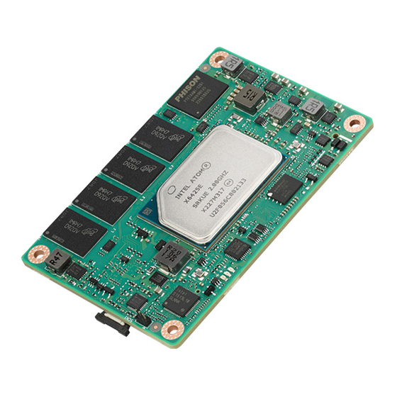
Board Information The figures below indicate the main chips on SOM-7532 Computer-on-Module. Please aware on these positions while design customer’s own carrier board to avoid mechanical violence and thermal solutions contacts for best thermal dispassion per- formance. ® ® ®... -
Page 27: Mechanical Diagram
Mechanical Diagram For more detail about 2D/3D models, please find on Advantech COM support service website http://com.advantech.com. Figure 2.3 Atom Series Board Mechanical Diagram – Front Figure 2.4 Atom Series Board Mechanical Diagram – Rear Figure 2.5 Atom Series Board Mechanical Diagram – Side... - Page 28 Figure 2.6 Pentium Series Board Mechanical Diagram – Front Figure 2.7 Pentium Series Board Mechanical Diagram – Rear Figure 2.8 Pentium Series Board Mechanical Diagram – Side SOM-7532 User Manual...
-
Page 29: Assembly Diagram
These figures demonstrate the order of assembly for attaching the thermal module and COM module to carrier board. Figure 2.9 Assembly Diagram There are 4 x reserved screw holes that enable SOM-7532 to be assembled with the heat spreader. SOM-7532 User Manual... -
Page 30: Assembly Diagram
Assembly Diagram Please consider the CPU and chip height tolerance when designing your thermal solution. Figure 2.10 CPU Height and Tolerance Figure 2.11 CPU Height and Tolerance SOM-7532 User Manual... -
Page 31: Chapter 3 Ami Bios
Chapter AMI BIOS This chapter gives BIOS setup information for the SOM-7532 CPU computer-on module. Sections include: Introduction Entering Setup Hot/Operation Key Exit BIOS Setup Utility... -
Page 32: Introduction
This information is stored in flash ROM so it retains the Setup information when the power is turned off. Entering Setup Turn on the computer and then press <DEL> or <ESC> to enter the Setup menu. SOM-7532 User Manual... -
Page 33: Main Setup
System Date using the <Arrow> keys. Enter new values through the keyboard. Press the <Tab> key or the <Arrow> keys to move between fields. The date must be entered in MM/DD/YY format. The time must be entered in HH:MM:SS format. SOM-7532 User Manual... -
Page 34: Advanced Bios Features Setup
Advanced BIOS Features Setup Select the Advanced tab from the SOM-7532 setup screen to enter the Advanced BIOS Setup screen. Users can select any item in the left frame of the screen, such as CPU Configuration, to go to the sub menu for that item. Users can display an Advanced BIOS Setup option by highlighting it using the <Arrow>... -
Page 35: Cpu Configuration
When enabled, a VMM can utilize the additional hardware capabilities provided by Vanderpool Technology. Active Processor Cores Number of cores to enable in each processor package. Enable/Disable AES(Advanced Encryption Standard) MonitorMwait Enable/Disable Monitor Mwait. SOM-7532 User Manual... -
Page 36: Power & Performance
3.4.2 Power & Performance Figure 3.5 Power & Performance CPU - Power Management Control CPU - Power Management Control Options GT - Power Management Control GT - Power Management Control Options SOM-7532 User Manual... - Page 37 CPPC v2 interface to allow for hardware controlled P-states. Turbo Mode Enable/Disable processor Turbo Mode (requires EMTTM enabled too). AUTO means enabled. C states Enable/Disable CPU Power Management. Allows CPU to go to C states when it's not 100% utilized. SOM-7532 User Manual...
- Page 38 3.4.2.2 GT - Power Management Control Figure 3.7 GT - Power Management Control RC6(Render Standby) Check to enable render standby support. SOM-7532 User Manual...
-
Page 39: Pch-Fw Configuration
ME Unconfig on RTC Clear When Disabled ME will nor unconfigured on RTC clear. Firmware Update Configuration Configure Management Engine Technology Parameters. OEM Key Revocation Configuration When enabled, BIOS will automatically send HECI command to revoke OEM keys. SOM-7532 User Manual... - Page 40 3.4.3.1 Firmware Update Configuration Figure 3.9 Firmware Update Configuration Me FW Image Re-Flash Enable/Disable Me FW Image Re-Flash function. FW Update Enable/Disable ME FW Update function. SOM-7532 User Manual...
-
Page 41: Trusted Computing
TPM 1.2 will restrict support to TPM 1.2 devices, TPM 2.0 will restrict support to TPM 2.0 devices, Auto will support both with the default set to TPM 2.0 devices if not found, TPM 1.2 devices will be enumerated. SOM-7532 User Manual... -
Page 42: Acpi Settings
Enables or Disables System ability to Hibernate (OS/S4 Sleep State). This option may be not effective with some OS. ACPI Sleep State Select the highest ACPI sleep state the system will enter when the SUSPEND button is pressed. SOM-7532 User Manual... -
Page 43: Embedded Controller
ACPI Report Method Configuration Select ACPI Reporting Method for EC Devices. CAN0 Control Enable/Disable CAN0 controller on RDC EIO-211. I2C0 Control Enable/Disable I2C0 controller on RDC EIO-211. SMBus0 Control Enable/Disable SMBus0 controller on RDC EIO-211. SOM-7532 User Manual... - Page 44 3.4.6.1 Serial Port 1 Configuration Figure 3.13 Serial Port 1 Configuration Serial Port Enable or Disable Serial Port (COM). Change Settings Select an optimal settings for Super IO Device. SOM-7532 User Manual...
- Page 45 3.4.6.2 Serial Port 2 Configuration Figure 3.14 Serial Port 2 Configuration Serial Port Enable or Disable Serial Port (COM). Change Settings Select an optimal settings for Super IO Device. SOM-7532 User Manual...
- Page 46 3.4.6.3 Hardware Monitor Figure 3.15 Hardware Monitor SOM-7532 User Manual...
-
Page 47: Serial Port Console Redirection
Console Redirection Enable or Disable. Console Redirection Settings The settings specify how the host computer and the remote computer (which the user is using) will exchange data. Both computers should have the same or compatible settings. SOM-7532 User Manual... -
Page 48: Usb Configuration
Maximum time the device will take before it properly reports itself to the Host Controller. 'Auto' uses default value: for a Root port it is 100 ms, for a Hub port the delay is taken from Hub descriptor. SOM-7532 User Manual... -
Page 49: Network Stack Configuration
Wait time in seconds to press ESC key to abort the PXE boot. Use either +/- or numeric keys to set the value. Media detect count Number of times presence of media will be checked. Use either +/- or numeric keys to set the value. SOM-7532 User Manual... -
Page 50: Nvme Configuration
3.4.10 NVME Configuration Figure 3.19 NVME Configuration SOM-7532 User Manual... -
Page 51: Sdio Configuration
Figure 3.20 SDIO Configuration SDIO Access Mode Auto Option: Access SD device in DMA mode if controller supports it, otherwise in PIO mode.DMA Option: Access SD device in DMA mode.PIO Option: Access SD device in PIO mode. SOM-7532 User Manual... -
Page 52: Chipset Setup
Chipset Setup Figure 3.21 Chipset Setup System Agent (SA) Configuration System Agent Parameters. PCH-I0 Configuration PCH parameters. SOM-7532 User Manual... -
Page 53: System Agent (Sa) Configuration
Memory Configuration Memory Configuration Parameters. Graphic Configuration VT-d VT-d capability. Above 4GB MMIO BIOS assignment Enable/Disable above 4GB memory mapped IO BIOS assignment. This is enabled automatically when aperture size is set to 2048MB. SOM-7532 User Manual... - Page 54 3.5.1.1 Memory Configuration Figure 3.23 Memory Configuration Max TOLUD Maximum value of TOLUD. Dynamic assignment would adjust TOLUD automat- ically based on the largest MMIO length of installed graphic controller. SOM-7532 User Manual...
- Page 55 DVMT Pre-Allocated Select DVMT5.0 pre-allocated (fixed) Graphics Memory size is used by the internal graphics device. DVMT Total Gfx Mem Select DVMT5.0 total graphic memory size is used by the internal graphic device. LCD Control SOM-7532 User Manual...
- Page 56 Secondary boot display selection will appear based on your selection. VGA modes will be supported only on pri- mary display. Panel Scaling – Select the LCD panel scaling option used by the Internal Graphics Device. SOM-7532 User Manual...
-
Page 57: Pch-Io Configuration
Pcie Ref Pll SSC Percentatge. AUTO - Keep hw default, no BIOS override. Range is 0.0%-0.5%. Flash Protection Range Registers (FPRR) Enable Flash Protection Range Registers. SPD Write Disable Enable/Disable setting SPD Write Disable. For security recommendations, SPD write disable bit must be set. SOM-7532 User Manual... - Page 58 Config PEG PCIe Lane 0~15 setting. PCI Express Root Port 1 PCI Express Root Port 2 PCI Express Root Port 3 PCI Express Root Port 4 PCI Express Root Port 5 SOM-7532 User Manual...
- Page 59 Figure 3.28 PCI Express Root Port 1 – PCI Express Root Port 1 Control the PCI Express Root Port. – ASPM PCI Express Active State Power Management settings. Hot Plug – PCI Express Hot Plug Enable/Disable. – PCIe Speed Configure PCIe Speed. SOM-7532 User Manual...
- Page 60 Figure 3.29 PCI Express Root Port 2 – PCI Express Root Port 2 Control the PCI Express Root Port. – ASPM PCI Express Active State Power Management settings. Hot Plug – PCI Express Hot Plug Enable/Disable. – PCIe Speed Configure PCIe Speed. SOM-7532 User Manual...
- Page 61 Figure 3.30 PCI Express Root Port 3 – PCI Express Root Port 3 Control the PCI Express Root Port. – ASPM PCI Express Active State Power Management settings. Hot Plug – PCI Express Hot Plug Enable/Disable. – PCIe Speed Configure PCIe Speed. SOM-7532 User Manual...
- Page 62 Figure 3.31 PCI Express Root Port 4 – PCI Express Root Port 4 Control the PCI Express Root Port. – ASPM PCI Express Active State Power Management settings. Hot Plug – PCI Express Hot Plug Enable/Disable. – PCIe Speed Configure PCIe Speed. SOM-7532 User Manual...
- Page 63 Figure 3.32 PCI Express Root Port 5 – PCI Express Root Port 5 Control the PCI Express Root Port. – ASPM PCI Express Active State Power Management settings. Hot Plug – PCI Express Hot Plug Enable/Disable. – PCIe Speed Configure PCIe Speed. SOM-7532 User Manual...
- Page 64 Figure 3.33 SATA Configuration SATA Controller(s) Enable/Disable SATA Device. SATA Controller Speed Indicates the maximum speed the SATA controller can support. Port 0 Enable or Disable SATA Port. Port 1 Enable or Disable SATA Port. SOM-7532 User Manual...
- Page 65 3.5.2.3 USB Configuration Figure 3.34 USB Configuration XHCI Compliance Mode Option to enable Compliance Mode. Default is to disable Compliance Mode. Change to enabled for Compliance Mode testing. SOM-7532 User Manual...
- Page 66 RTC Memory Lock Enable will lock bytes 38h-3Fh in the lower/upper 126 –byte bank of RTC RAM. BIOS Lock Enable/Disable the PCH BIOS lock enable feature. Required to be enabled to ensure SMM protection of flash. SOM-7532 User Manual...
- Page 67 3.5.2.5 HD Audio Subsystem Configuration Settings Figure 3.36 HD Audio Subsystem Configuration Settings HD Audio Control Detection of the HD-Audio device. Disabled=HDA will be unconditionally disabled. Enabled=HDA will be unconditionally enabled. SOM-7532 User Manual...
- Page 68 UART 0 (00:30:00) cannot be disabled when: 1. Child device is enabled like CNVi Bluetooth (\_SB.PC00.UA00.BTH0) UART 0 (00:30:00) cannot be enabled when: 1. I2S Audio codec is enabled (\_SB.PC00.I2C0.HDAC) Serial IO I2C2 Settings Serial IO I2C4 Settings SOM-7532 User Manual...
- Page 69 FastSpeedPlus SCL High – FastSpeedPlus SCL High – FastSpeedPlus SCL Low – FastSpeedPlus SDA Hold – HighSpeed SCL High – HighSpeed SCL Low – HighSpeed SDA Hold – D0->D3 idle timeout (screen off) – D0->D3 idle timeout (screen on) SOM-7532 User Manual...
- Page 70 FastSpeedPlus SCL High – FastSpeedPlus SCL High – FastSpeedPlus SCL Low – FastSpeedPlus SDA Hold – HighSpeed SCL High – HighSpeed SCL Low – HighSpeed SDA Hold – D0->D3 idle timeout (screen off) – D0->D3 idle timeout (screen on) SOM-7532 User Manual...
- Page 71 3.5.2.7 SCS Configuration Figure 3.40 SCS Configuration eMMC 5.1 Controller Enable or Disable SCS eMMC 5.1 Controller. SDCard 3.0 Controller Enable or Disable SCS SDHC 3.0 Controller. SOM-7532 User Manual...
-
Page 72: Security Chipset
Security Chipset Figure 3.41 Security Chipset Administrator Password Set Setup Administrator Password. User Password Set User Password. Secure Boot Secure Boot Configuration. SOM-7532 User Manual... -
Page 73: Secure Boot
System is in User mode. The mode change requires platform reset. Secure Boot Mode Secure Boot mode options: Standard or Custom. In Custom mode, Secure Boot Policy variables can be configured by a physi- cally present user without full authentication. SOM-7532 User Manual... -
Page 74: Boot Setup
Select the keyboard NumLock state. Quiet Boot Enables or disables Quiet Boot option. Boot Option #1 Sets the system boot order. Fast Boot Enable or Disable FastBoot features. Most probes are skipped to reduce time cost during boot. SOM-7532 User Manual... -
Page 75: Save & Exit
Restore/Load Default values for all the setup options. Save as User Defaults Save the changes done so far as User Defaults. Restore User Defaults Restore the User Defaults to all the setup options. Boot Override SOM-7532 User Manual... - Page 76 SOM-7532 User Manual...
-
Page 77: Chapter 4 S/W Introduction And Installation
Chapter S/W Introduction and Installation S/W Introduction Driver Installation Advantech iManager... -
Page 78: S/W Introduction
S/W Introduction The mission of Advantech Embedded Software Services is to "Enhance quality of life with Advantech platforms and Microsoft Windows embedded technology." We enable Windows Embedded software products on Advantech platforms to more effectively support the embedded computing community. Customers are freed from the hassle of dealing with multiple vendors (Hardware suppliers, System integrators, Embedded OS distributor) for projects. -
Page 79: Advantech Imanager
It makes these embedded features easier to integrate, speed up develop- ing schedule, and provide the customer’s software continuity while upgrade hard- ware. More detail of how to use the APIs and utilities, please refer to Advantech iManager2.0 Software API User Manual. - Page 80 SOM-7532 User Manual...
-
Page 81: Appendix A Pin Assignment
Appendix Pin Assignment This appendix gives you the infor- mation about the hardware pin assignment of the SOM-7532 CPU System on Module. Sections include: SOM-7532 Type 10 Pin Assign- ment... -
Page 82: Som-7532 Pin Assignment
This section gives SOM-7532 pin assignment on COM Express connector which compliant with COME R3.0 Type 10 pin-out definitions. More details about how to use these pins and get design reference, please contact to Advantech for design guide, checklist, reference schematic, and other hardware/software supports. - Page 83 GND (FIXED) LVDS_A0+ DDI0_PAIR0+ LVDS_A0- DDI0_PAIR0- LVDS_A1+ DDI0_PAIR1+ LVDS_A1- DDI0_PAIR1- LVDS_A2+ DDI0_PAIR2+ LVDS_A2- DDI0_PAIR2- LVDS_VDD_EN LVDS_A3+ LVDS_A3- LVDS_BKLT_EN GND (FIXED) GND (FIXED) LVDS_A_CK+ DDI0_PAIR3+ LVDS_A_CK- DDI0_PAIR3- LVDS_I2C_CK LVDS_BKLT_CTRL LVDS_I2C_DAT VCC_5V_SBY GPI3 VCC_5V_SBY RSVD VCC_5V_SBY eDP_HPD VCC_5V_SBY PCIE_CLK_REF+ BIOS_DIS1# SOM-7532 User Manual...
- Page 84 A73 could be an optional pin reserved for eDP_TX2-. Please contact FAE for details. A74 could be an optional pin reserved for eDP_TX1+. Please contact FAE for details. A75 could be an optional pin reserved for eDP_TX1-. Please contact FAE for details. SOM-7532 User Manual...
- Page 85 B54 could be an optional pin reserved for SD_SDIO_CMD. Please contact FAE for details. B55 could be an optional pin reserved for FUSA_ISI_MOSI. Please contact FAE for details. B56 could be an optional pin reserved for FUSA_ISI_MISO. Please contact FAE for details. SOM-7532 User Manual...
- Page 86 B79 could be an optional pin reserved for eDP_BKLT_EN. Please contact FAE for details. B83 could be an optional pin reserved for eDP_BKLT_CTRL. Please contact FAE for details. B97 could be an optional pin reserved for GSPI_CS#. Please contact FAE for details. SOM-7532 User Manual...
-
Page 87: Appendix B Watchdog Timer
Appendix Watchdog Timer This appendix gives you the infor- mation about the watchdog timer programming on the SOM-7532 CPU System on Module. Sections include: Watchdog Timer Programming... -
Page 88: Programming The Watchdog Timer
** WDT new driver support automatically select available IRQ number from BIOS, and then set to EC. Only Win10 support it. In other OS, it will still use IRQ number from BIOS setting as usual. For details, please refer to iManager & Software API User Manual. SOM-7532 User Manual... -
Page 89: Appendix C Programming Gpio
Appendix Programming GPIO This Appendix illustrates the Gen- eral Purpose Input and Output pin settings. Sections include: GPIO Register... -
Page 90: Gpio Register
GPIO Register GPIO Byte Mapping H/W Pin Name BIT0 GPI0 BIT1 GPI1 BIT2 GPI2 BIT3 GPI3 BIT4 GPO0 BIT5 GPO1 BIT6 GPO2 BIT7 GPO4 For details, please refer to the iManager and Software API User Manual. SOM-7532 User Manual... -
Page 91: Appendix D System Assignments
Appendix System Assignments This appendix gives you the infor- mation about the system resource allocation on the SOM-7532 CPU System on Module. Sections include: System I/O ports DMA Channel Assignments Interrupt Assignments 1 MB Memory Map... -
Page 92: System I/O Ports
0x00000D00-0x0000FFFF PCI Express Root Complex 0x00000020-0x00000021 Programmable interrupt controller 0x00000024-0x00000025 Programmable interrupt controller 0x00000028-0x00000029 Programmable interrupt controller 0x0000002C-0x0000002D Programmable interrupt controller 0x00000030-0x00000031 Programmable interrupt controller 0x00000034-0x00000035 Programmable interrupt controller 0x00000038-0x00000039 Programmable interrupt controller 0x0000003C-0x0000003D Programmable interrupt controller SOM-7532 User Manual... -
Page 93: Interrupt Assignments
Numeric data processor IRQ 19 Intel(R) Active Management Technology - SOL (COM3) IRQ 16 High Definition Audio Controller IRQ 4294967281 Intel(R) Ethernet Controller (3) I225-LM IRQ 4294967291 Intel(R) UHD Graphics IRQ 4294967280 Intel(R) Management Engine Interface #1 SOM-7532 User Manual... -
Page 94: 1St Mb Memory Map
Trusted Platform Module 2.0 0xFE010000-0xFE010FFF Intel(R) SPI (flash) Controller - 43A4 0xBFFFF000-0xBFFFFFFF Intel(R) Active Management Technology - SOL (COM3) 0xFFEFC000-0xFFEFFFFF High Definition Audio Controller 0xFFF00000-0xFFFFFFFF High Definition Audio Controller 0x1110000-0x111FFFF Intel(R) USB 3.10 eXtensible Host Controller - 1.20 (Microsoft) SOM-7532 User Manual... - Page 95 Table D.3: 1st MB Memory Map 0x50500000-0x505FFFFF Intel(R) Ethernet Controller (3) I225-LM 0x50600000-0x50603FFF Intel(R) Ethernet Controller (3) I225-LM 0x0000-0xFFFFFF Intel(R) UHD Graphics 0x0000-0xFFFFFFF Intel(R) UHD Graphics 0xFFEFB000-0xFFEFBFFF Intel(R) Management Engine Interface #1 0xFFEFA000-0xFFEFAFFF Intel(R) Serial IO I2C Host Controller - 43E8 SOM-7532 User Manual...
- Page 96 No part of this publication may be reproduced in any form or by any means, such as electronically, by photocopying, recording, or otherwise, without prior written permission from the publisher. All brand and product names are trademarks or registered trademarks of their respective companies. © Advantech Co., Ltd. 2023...
Need help?
Do you have a question about the SOM-7532 and is the answer not in the manual?
Questions and answers