Sign In
Upload
Manuals
Brands
Nuvoton Manuals
Motherboard
NuMaker-HMI-MA35H0-A1
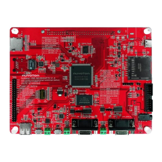
Nuvoton NuMaker-HMI-MA35H0-A1 Manuals
Manuals and User Guides for Nuvoton NuMaker-HMI-MA35H0-A1. We have
2
Nuvoton NuMaker-HMI-MA35H0-A1 manuals available for free PDF download: User Manual
Nuvoton NuMaker-HMI-MA35H0-A1 User Manual (55 pages)
Evaluation Board for NuMicro MA35H0 Series
Brand:
Nuvoton
| Category:
Motherboard
| Size: 3 MB
Table of Contents
Table of Contents
2
Overview
7
Figure 1-1 Numaker-HMI-MA35H0-A1/A2 Board from Target Chip Side
8
Figure 1-2 Numaker-HMI-MA35H0-A1 from TFT LCD Side (with RTP)
8
Figure 1-3 Numaker-HMI-MA35H0-A2 from TFT LCD Side (with CTP)
9
Numaker-HMI-MA35H04F70 Board
10
Numaker TFT-LCD7 Board
10
Figure 1-4 Numaker-HMI-MA35H04F70 Board
10
Figure 1-5 Numaker-TFT-LCD7 (RTP) Board
11
Figure 1-6 Numaker-TFT-LCD7 (CTP) Board
11
Order Number and Part Number of EVB
12
Table 1-1 Board Part Number and Information
12
Features
13
Numaker-HMI-MA35H04F70 Board Features
13
Numaker TFT-LCD7 Board Features
13
Hardware Configuration
14
Numaker-HMI-MA35H04F70 Board
14
Front View
14
Rear View
14
Figure 3-1 Front View of Numaker-HMI-MA35H04F70
14
DDR PHY and MCP DRAM Power Voltage
15
Audio Codec
15
Figure 3-2 Rear View of Numaker-HMI-MA35H04F70
15
Table 3-1 DDR PHY and MCP DRAM Power Voltage Selection
15
RMII Megabit Ethernet
16
Table 3-2 I2S0 (U21) Pin Function
16
Table 3-3 I2C0 (U21) Pin Function
16
Table 3-4 Audio Codec (U21) Control Pin Function
16
QSPI Flash
17
Table 3-5 RMII0 Pin Function
17
Table 3-6 Transformer (U17) Pin Function
17
NAND Flash
18
USB Virtual COM (VCOM) Port
18
Table 3-7 QSPI0 Flash (U11) Pin Function
18
Table 3-8 NAND Flash (U12) Pin Function
18
Powered by USB Type-C
19
Power-On Setting
19
Table 3-9 NUC123 ICE Interface (J16) Pin Funciton
19
Table 3-10 Secure Boot Options
19
Table 3-11 Booting Source QSPI0 and Sd/Emmc IO Voltage Options
19
Table 3-12 Booting Source Options
20
Table 3-13 Page Size Options for NAND Flash Booting Source
20
Table 3-14 ECC Options for NAND Flash Booting Source
20
Table 3-15 Options for SD Card 0/1 or Emmc 0/1 Device Booting Source
21
Table 3-16 4/8-Bit Options for Emmc NAND Flash Device Booting Source
21
Table 3-17 1-Bit Options for QSPI0 NAND/NOR Flash Booting Source
21
Table 3-18 Options for USBD or USBH Booting Source
21
Table 3-19 USBH Port 0/1 Options for USBH Booting Source
21
Table 3-20 Over-Current High/Low-Active Detect Options for USBH Booting Source
21
Reset and RTC Wake-Up Control
22
TFT LCD Connector
22
Table 3-21 RTC Power Control Pins of MA35H0
22
Swj
24
Table 3-22 LCM Connecor (CON14) Pin Function
24
HS USB2.0 Connectors
25
Table 3-23 SWJ Interface (CON12) Pin Funciton
25
RS232 or RS485
26
Table 3-24 RS232_6 Connector (CON24) Pin Funciton
26
Table 3-25 RS485_6 Connector (J71) Pin Funciton
26
Can Fd
27
Key Buttons and Leds
27
Table 3-26 RS232_16 Connector (CON25) Pin Funciton
27
Table 3-27 RS485_16 Connector (J65) Pin Funciton
27
Table 3-28 CAN_0 Header (J2) Pin Funciton
27
Table 3-29 Key Buttons (KEY_0, KEY_1, KEY_2) Pin Function
27
Table 3-30 Leds (LED_0, LED_1, LED_2) Pin Function
27
SD Card and Microsd Card Slot
28
Table 3-31 SD0 Microsd Card Slot (CON34) Pin Function
28
Table 3-32 SD1 Standard SD Card Slot (CON32) Pin Function
29
Table 3-33 PN11 Pin State Control for SD1 VDD_SDIO 3.3V or 1.8V Power Voltage
29
Table 3-34 PK9 or Nreset Pin State Control for SD1 Standard SD Card Power on or off
29
Numaker TFT-LCD7 Board
30
Front View
30
Rear View
30
Figure 3-3 Front View of Numaker TFT-LCD7 Board
30
Connectors
31
Figure 3-4 Rear View of Numaker TFT-LCD7 Board
31
Quick Start
32
Configure Power-On Setting
32
Figure 4-1 Power-On Setting DIP Switch (SW7)
32
Table 4-1 Secure Boot Disable Configuration
32
Power on the System
33
VCOM Port (Optional)
33
Press the RTC Wakeup Key Button
33
CTP Settings
33
Figure 4-2 USB VCOM Port (CON9)
33
Figure 4-3 RTC Wakeup Key Button (SW1)
33
Supporting Resources
35
Documents
35
Software
35
Figure 5-1 Nuvoton Website
35
Figure 5-2 MA35H0 Github Resources
36
Numaker-Hmi-Ma35H0-A1/A2 Schematics
37
Numaker-HMI-MA35H04F70 Schematic
37
Power Input Schematic
37
Figure 6-1 Power Input Schematic
37
ADC and Reset Buttons Schematic
38
Figure 6-2 ADC and Reset Buttons Schematic
38
Power-On Setting and SWJ Schematic
39
Figure 6-3 Power-On Setting and SWJ Schematic
39
Key Buttons Schematic
40
Figure 6-4 Key Buttons Schematic
40
LCM Schematic
41
Figure 6-5 LCM Schematic
41
QSPI0 and NAND Flash Schematic
42
Figure 6-6 QSPI0 and NAND Flash Schematic
42
SD0 Schematic
43
Figure 6-7 SD0 Schematic
43
SD1 Schematic
44
Figure 6-8 SD1 Schematic
44
RMII0_PF Schematic
45
Figure 6-9 RMII0 Schematic
45
GPIO Schematic
46
Figure 6-10 GPIO Schematic
46
NAU88C22 Audio Codec Schematic
47
Figure 6-11 NAU88C22 Audio Codec Schematic
47
NUC123 VCOM Schematic
48
Figure 6-12 NUC123 VCOM Schematic
48
HSUSB 0/1 Schematic
49
Figure 6-13 HSUSB 0/1 Schematic
49
LED, CAN FD, RS232 and RS485 Schematic
50
Figure 6-14 LED, CAN FD, RS232 and RS485 Schematic
50
PCB Placement
51
Figure 6-15 Front PCB Placement of Numaker-HMI-MA35H070 Board
51
Figure 6-16 Rear PCB Placement of Numaker-HMI-MA35H070 Board
52
Numaker TFT-LCD7 Board Schematic
53
Figure 6-17 Numaker TFT-LCD7 Board Schematic
53
Revision History
54
Advertisement
Nuvoton NuMaker-HMI-MA35H0-A1 User Manual (53 pages)
Arm® Cortex® -A35-based Microprocessor
Brand:
Nuvoton
| Category:
Motherboard
| Size: 3 MB
Table of Contents
Table of Contents
2
Overview
7
Figure 1-1 Numaker-HMI-MA35H0-A1 Board
8
Figure 1-2 Rear View of Numaker-HMI-MA35H0-A1
8
Numaker-HMI-MA35H04F70 Board
9
Figure 1-3 Numaker-HMI-MA35H04F70 Board
9
Numaker TFT-LCD7 Board
10
Figure 1-4 Numaker-TFT-LCD7 Board
10
Board Part Number and Information
11
Table 1-1 Board Part Number and Information
11
Features
12
Numaker-HMI-MA35H04F70 Board Features
12
Numaker TFT-LCD7 Board Features
12
Hardware Configuration
13
Numaker-HMI-MA35H04F70 Board
13
Front View
13
Rear View
13
Figure 3-1 Front View of Numaker-HMI-MA35H04F70
13
DDR PHY and MCP DRAM Power Voltage
14
Audio Codec
14
Figure 3-2 Rear View of Numaker-HMI- MA35H04F70
14
Table 3-1 DDR PHY and MCP DRAM Power Voltage Selection
14
RMII Megabit Ethernet
15
Table 3-2 I2S0 (U21) Pin Function
15
Table 3-3 I2C0 (U21) Pin Function
15
Table 3-4 Audio Codec (U21) Control Pin Function
15
QSPI Flash
16
Table 3-5 RMII0 Pin Function
16
Table 3-6 Transformer (U17) Pin Function
16
NAND Flash
17
USB Virtual COM (VCOM) Port
17
Table 3-7 QSPI0 Flash (U11) Pin Function
17
Table 3-8 NAND Flash (U12) Pin Function
17
Powered by USB Type C
18
Power-On Setting
18
Table 3-9 NUC123 ICE Interface (J16) Pin Funciton
18
Table 3-10 Secure Boot Options
18
Table 3-11 Booting Source QSPI0 and Sd/Emmc IO Voltage Options
18
Table 3-12 Booting Source Options
19
Table 3-13 Page Size Options for NAND Flash Booting Source
19
Table 3-14 ECC Options for NAND Flash Booting Source
19
Table 3-15 Options for SD Card 0/1 or Emmc 0/1 Device Booting Source
20
Table 3-16 4/8-Bit Options for Emmc NAND Flash Device Booting Source
20
Table 3-17 1-Bit Options for QSPI0 NAND/NOR Flash Booting Source
20
Table 3-18 Options for USBD or USBH Booting Source
20
Table 3-19 USBH Port 0/1 Options for USBH Booting Source
20
Table 3-20 Over-Current High/Low-Active Detect Options for USBH Booting Source
20
Reset and RTC Wake-Up Control
21
TFT LCD Connector
21
Table 3-21 RTC Power Control Pins of MA35H0
21
Swj
23
Table 3-22 LCM Connecor (CON9) Pin Function
23
HS USB2.0 Connectors
24
Table 3-23 SWJ Interface (CON12) Pin Funciton
24
RS232 or RS485
25
Table 3-24 RS232_6 Connector (CON24) Pin Funciton
25
Table 3-25 RS485_6 Connector (J71) Pin Funciton
25
Can Fd
26
Key Buttons and Leds
26
Table 3-26 RS232_16 Connector (CON25) Pin Funciton
26
Table 3-27 RS485_16 Connector (J65) Pin Funciton
26
Table 3-28 CAN_0 Header (J2) Pin Funciton
26
Table 3-29 Key Buttons (KEY_0, KEY_1, KEY_2) Pin Function
26
Table 3-30 Leds (LED_0 , LED_1, LED_2) Pin Function
26
SD Card and Microsd Card Slot
27
Table 3-31 SD0 Microsd Card Slot (CON34) Pin Function
27
Table 3-32 SD1 Standard SD Card Slot (CON32) Pin Function
28
Table 3-33 PN11 Pin State Control for SD1 VDD_SDIO 3.3V or 1.8V Power Voltage
28
Table 3-34 PK9 or Nreset Pin State Control for SD1 Standard SD Card Power on or off
28
Numaker TFT-LCD7 Board
29
Front View
29
Rear View
29
Figure 3-3 Front View of Numaker TFT-LCD7 Board
29
Connectors
30
Figure 3-4 Rear View of Numaker TFT-LCD7 Board
30
Quick Start
31
Configure Power-On Setting
31
Figure 4-1 Power-On Setting DIP Switch (SW7)
31
Table 4-1 Secure Boot Disable Configuration
31
Power on the System
32
VCOM Port (Optional)
32
Press the RTC Wakeup Key Button
32
Figure 4-2 USB VCOM Port (CON9)
32
Figure 4-3 RTC Wakeup Key Button (SW1)
32
Supporting Resources
33
Documents
33
Software
33
Figure 5-1 Nuvoton Website
33
Figure 5-2 MA35H0 Github Resources
34
Numaker-Hmi-Ma35H0-A1 Schematics
35
Numaker-HMI-MA35H04F70 Schematic
35
Power Input Schematic
35
Figure 6-1 Power Input Schematic
35
ADC and Reset Buttons Schematic
36
Figure 6-2 ADC and Reset Buttons Schematic
36
Power-On Setting and SWJ Schematic
37
Figure 6-3 Power-On Setting and SWJ Schematic
37
Key Buttons Schematic
38
Figure 6-4 Key Buttons Schematic
38
LCM Schematic
39
Figure 6-5 LCM Schematic
39
QSPI0 and NAND Flash Schematic
40
Figure 6-6 QSPI0 and NAND Flash Schematic
40
SD0 Schematic
41
Figure 6-7 SD0 Schematic
41
SD1 Schematic
42
Figure 6-8 SD1 Schematic
42
RMII0_PF Schematic
43
Figure 6-9 RMII0 Schematic
43
GPIO Schematic
44
Figure 6-10 GPIO Schematic
44
NAU88C22 Audio Codec Schematic
45
Figure 6-11 NAU88C22 Audio Codec Schematic
45
NUC123 VCOM Schematic
46
Figure 6-12 NUC123 VCOM Schematic
46
HSUSB 0/1 Schematic
47
Figure 6-13 HSUSB 0/1 Schematic
47
LED, CAN FD, RS232 and RS485 Schematic
48
Figure 6-14 LED, CAN FD, RS232 and RS485 Schematic
48
PCB Placement
49
Figure 6-15 Front PCB Placement of Numaker-HMI-MA35H070 Board
49
Figure 6-16 Rear PCB Placement of Numaker-HMI-MA35H070 Board
50
Numaker TFT-LCD7 Board Schematic
51
Figure 6-17 Numaker TFT-LCD7 Board Schematic
51
Revision History
52
Advertisement
Related Products
Nuvoton NuMicro NuMaker-HMI-N9H20
Nuvoton NuMaker-HMI-N9H26
Nuvoton NuMaker-HMI-M032K
Nuvoton NuMaker-HMI-N9H30
Nuvoton NuMaker-HMI-M467
Nuvoton NuMicro NuMaker-HMI-MA35D1-S1
Nuvoton NuMaker-HMI-MA35H0-A2
Nuvoton NuMaker-HMI-N9H31-A1
Nuvoton NuMaker-HMI-N9H31-A2
Nuvoton NuMicro NuMaker-M0A23EC
Nuvoton Categories
Motherboard
Microcontrollers
Computer Hardware
Amplifier
Computer Accessories
More Nuvoton Manuals
Login
Sign In
OR
Sign in with Facebook
Sign in with Google
Upload manual
Upload from disk
Upload from URL