Sign In
Upload
Manuals
Brands
Nuvoton Manuals
Microcontrollers
NuMicro series
Nuvoton NuMicro series ARM Cortex-M0 MCU Manuals
Manuals and User Guides for Nuvoton NuMicro series ARM Cortex-M0 MCU. We have
16
Nuvoton NuMicro series ARM Cortex-M0 MCU manuals available for free PDF download: Technical Reference Manual, User Manual, Quick Start Manual
Nuvoton NuMicro series Technical Reference Manual (401 pages)
8-bit Microcontroller
Brand:
Nuvoton
| Category:
Microcontrollers
| Size: 5 MB
Table of Contents
Table of Contents
2
General Description
12
Features
14
Part Information
17
3.1 ML51 Series Selection Guide
17
3.2 ML51 Series Selection Code
18
Pin Configuration
19
ML51 Series Pin Diagram
19
Figure 4.1-1 Pin Assignment of QFN-33 Package
19
Figure 4.1-2 Pin Assignment of LQFP-32 Package
20
Figure 4.1-3 Pin Assignment of TSSOP-28 Package
20
Figure 4.1-4 Pin Assignment of SOP-28 Package
21
Figure 4.1-5 Pin Assignment of TSSOP-20 Package
21
Figure 4.1-6 Pin Assignment of TSSOP-20 Package
22
Figure 4.1-7 Pin Assignment of QFN-20 Package
22
Figure 4.1-8 Pin Assignment of TSSOP-14 Package
23
Figure 4.1-9 Pin Assignment of MSOP-10 Package
23
ML51 Series Multi Function Pin Diagram
24
Figure 4.1-10 Multi Function Pin Assignment of QFN-33 Package
24
Figure 4.1-11 Multi Function Pin Assignment of LQFP-32 Package
25
Figure 4.1-12 Multi Function Pin Assignment of TSSOP-28 Package
26
Figure 4.1-13 Multi Function Pin Assignment of SOP-28 Package
26
Figure 4.1-14 Multi Function Pin Assignment of TSSOP-20 Package
26
Figure 4.1-15 Multi Function Pin Assignment of SOP-20 Package
27
Figure 4.1-16 Multi Function Pin Assignment of QFN-20 Package
27
Figure 4.1-17 Multi Function Pin Assignment of Package
28
Figure 4.1-18 Pin Assignment of MSOP-10 Package
28
4.2 Pin Description
29
Block Diagram
37
5.1 Ml51 Full Function Block
37
Figure 5.1-1 Functional Block Diagram
37
Memory Organization
38
6.1 Program Memory
38
6.2 Data Memory
40
Figure 6.1-1 ML51 Program Memory Map
40
Figure 6.2-1 Data Memory Map
40
Figure 6.2-2 Internal 256 Bytes RAM Addressing
42
6.3 On-Chip XRAM
43
6.4 Data Flash
43
Special Function Register (Sfr)
44
Sfr
44
Table 7.1-1 Special Function Register (SFR) Memory Map
45
Table 7.1-2 SFR Definitions and Reset Values
47
7.2 All SFR Description
63
General 80C51 System Control
152
Table 7.2-1 Instructions that Affect Flag Settings
154
O Port Structure and Operation
156
9.1 Quasi-Bidirectional Mode
156
Table 7.2-1 Configuration for Different I/O Modes
156
9.2 Push-Pull Mode
157
Figure 9.1-1 Quasi-Bidirectional Mode Structure
157
Figure 9.2-1 Push-Pull Mode Structure
157
9.3 Input-Only Mode
159
9.4 Open-Drain Mode
159
9.5 Read-Modify-Write Instructions
159
Figure 9.3-1 Input-Only Mode Structure
159
Figure 9.4-1 Open-Drain Mode Structure
159
9.6 Control Registers of I/O Ports
160
Input and Output Data Control
160
GPIO Mode Control
163
GPIO Multi-Function Select
164
Input Type
166
Output Slew Rate Control
167
Pull-Up Resister Control
168
Figure 10.1-1 Timer/Counters 0 and 1 in Mode 0
175
Figure 10.2-1 Timer/Counters 0 and 1 in Mode 1
175
Figure 10.3-1 Timer/Counters 0 and 1 in Mode 2
176
Figure 10.4-1 Timer/Counter 0 in Mode 3
177
Figure 10.4-1 Timer 2 Block Diagram
178
Figure 11.1-1 Timer 2 Auto-Reload Mode and Input Capture Module Functional Block Diagram
182
Figure 11.2-1 Timer 2 Compare Mode and Input Capture Module Functional Block Diagram
183
Figure 11.4-1 Timer 3 Block Diagram
189
Figure 13.1-1 WDT as a Time-Out Reset Timer
193
Table 11.4-1 Watchdog Timer-Out Interval under Different Pre-Scalars
193
Figure 13.2-1 Watchdog Timer Block Diagram
194
Figure 13.2-1 Self Wake-Up Timer Block Diagram
196
Figure 15.1-1 Serial Port Mode 0 Timing Diagram
199
Figure 15.2-1 Serial Port Mode 1 Timing Diagram
200
Figure 15.3-1 Serial Port Mode 2 and 3 Timing Diagram
201
Table 15.5-1 Serial Port 0 Mode / Baudrate Description
202
Table 15.5-2 Serial Port 1 Mode / Baudrate Description
203
Figure 16.1-1 SC Controller Block Diagram
216
Figure 16.4-1 SC Data Character
228
Figure 16.4-2 Initial Character TS
229
Figure 16.4-3 SC Error Signal
229
Figure 16.4-4 Transmit Direction Block Guard Time Operation
230
Figure 16.4-5 Receive Direction Block Guard Time Operation
230
Figure 16.4-6 Extra Guard Time Operation
230
Figure 17.1-1 SPI Block Diagram
231
Figure 17.1-2 SPI Multi-Master, Multi-Slave Interconnection
232
Figure 17.1-3 SPI Single-Master, Single-Slave Interconnection
233
Table 17.2-1 Slave Select Pin Configurations
238
Figure 17.4-1 SPI Clock Formats
241
Figure 17.4-2 SPI Clock and Data Format with CPHA = 0
242
Figure 17.4-3 SPI Clock and Data Format with CPHA = 1
242
Figure 17.8-1 SPI Overrun Waveform
244
Figure 17.9-1 SPI Interrupt Request
244
Figure 18.1-1 I 2 C Bus Interconnection
245
Figure 18.1-2 I 2 C Bus Protocol
246
Figure 18.1-3 START, Repeated START, and STOP Conditions
247
Figure 18.1-4 Master Transmits Data to Slave by 7-Bit
247
Figure 18.1-5 Master Reads Data from Slave by 7-Bit
248
Figure 18.1-6 Data Format of One I C Transfer
248
Figure 18.1-7 Acknowledge Bit
249
Figure 18.1-8 Arbitration Procedure of Two Masters
250
Figure 18.1-9 Control I C Bus According to the Current I C Status
251
Figure 18.1-10 Flow and Status of Master Transmitter Mode
252
Figure 18.1-11 Flow and Status of Master Receiver Mode
253
Figure 18.1-12 Flow and Status of Slave Receiver Mode
255
Figure 18.1-13 Flow and Status of General Call Mode
256
Figure 18.4-1 I 2 C Time-Out Counter
267
Figure 18.5-1 Pin Interface Block Diagram
269
Figure 20.1-1 PWM Block Diagram
275
Figure 20.1-2 PWM and Fault Brake Output Control Block Diagram
276
Figure 20.1-3 PWM Edge-Aligned Type Waveform
282
Figure 20.1-4 PWM Center-Aligned Type Waveform
283
Figure 20.1-5 PWM Complementary Mode with Dead-Time Insertion
285
Figure 20.1-6 Fault Brake Function Block Diagram
288
Figure 20.2-1 PWM Interrupt Type
292
Figure 21.1-1 12-Bit ADC Block Diagram
293
Figure 21.1-2 External Triggering ADC Circuit
295
Advertisement
Nuvoton NuMicro series User Manual (53 pages)
Arm® Cortex® -A35-based Microprocessor
Brand:
Nuvoton
| Category:
Motherboard
| Size: 3 MB
Table of Contents
Table of Contents
2
Overview
7
Figure 1-1 Numaker-HMI-MA35H0-A1 Board
8
Figure 1-2 Rear View of Numaker-HMI-MA35H0-A1
8
Numaker-HMI-MA35H04F70 Board
9
Figure 1-3 Numaker-HMI-MA35H04F70 Board
9
Numaker TFT-LCD7 Board
10
Figure 1-4 Numaker-TFT-LCD7 Board
10
Board Part Number and Information
11
Table 1-1 Board Part Number and Information
11
Features
12
Numaker-HMI-MA35H04F70 Board Features
12
Numaker TFT-LCD7 Board Features
12
Hardware Configuration
13
Numaker-HMI-MA35H04F70 Board
13
Front View
13
Rear View
13
Figure 3-1 Front View of Numaker-HMI-MA35H04F70
13
DDR PHY and MCP DRAM Power Voltage
14
Audio Codec
14
Figure 3-2 Rear View of Numaker-HMI- MA35H04F70
14
Table 3-1 DDR PHY and MCP DRAM Power Voltage Selection
14
RMII Megabit Ethernet
15
Table 3-2 I2S0 (U21) Pin Function
15
Table 3-3 I2C0 (U21) Pin Function
15
Table 3-4 Audio Codec (U21) Control Pin Function
15
QSPI Flash
16
Table 3-5 RMII0 Pin Function
16
Table 3-6 Transformer (U17) Pin Function
16
NAND Flash
17
USB Virtual COM (VCOM) Port
17
Table 3-7 QSPI0 Flash (U11) Pin Function
17
Table 3-8 NAND Flash (U12) Pin Function
17
Powered by USB Type C
18
Power-On Setting
18
Table 3-9 NUC123 ICE Interface (J16) Pin Funciton
18
Table 3-10 Secure Boot Options
18
Table 3-11 Booting Source QSPI0 and Sd/Emmc IO Voltage Options
18
Table 3-12 Booting Source Options
19
Table 3-13 Page Size Options for NAND Flash Booting Source
19
Table 3-14 ECC Options for NAND Flash Booting Source
19
Table 3-15 Options for SD Card 0/1 or Emmc 0/1 Device Booting Source
20
Table 3-16 4/8-Bit Options for Emmc NAND Flash Device Booting Source
20
Table 3-17 1-Bit Options for QSPI0 NAND/NOR Flash Booting Source
20
Table 3-18 Options for USBD or USBH Booting Source
20
Table 3-19 USBH Port 0/1 Options for USBH Booting Source
20
Table 3-20 Over-Current High/Low-Active Detect Options for USBH Booting Source
20
Reset and RTC Wake-Up Control
21
TFT LCD Connector
21
Table 3-21 RTC Power Control Pins of MA35H0
21
Swj
23
Table 3-22 LCM Connecor (CON9) Pin Function
23
HS USB2.0 Connectors
24
Table 3-23 SWJ Interface (CON12) Pin Funciton
24
RS232 or RS485
25
Table 3-24 RS232_6 Connector (CON24) Pin Funciton
25
Table 3-25 RS485_6 Connector (J71) Pin Funciton
25
Can Fd
26
Key Buttons and Leds
26
Table 3-26 RS232_16 Connector (CON25) Pin Funciton
26
Table 3-27 RS485_16 Connector (J65) Pin Funciton
26
Table 3-28 CAN_0 Header (J2) Pin Funciton
26
Table 3-29 Key Buttons (KEY_0, KEY_1, KEY_2) Pin Function
26
Table 3-30 Leds (LED_0 , LED_1, LED_2) Pin Function
26
SD Card and Microsd Card Slot
27
Table 3-31 SD0 Microsd Card Slot (CON34) Pin Function
27
Table 3-32 SD1 Standard SD Card Slot (CON32) Pin Function
28
Table 3-33 PN11 Pin State Control for SD1 VDD_SDIO 3.3V or 1.8V Power Voltage
28
Table 3-34 PK9 or Nreset Pin State Control for SD1 Standard SD Card Power on or off
28
Numaker TFT-LCD7 Board
29
Front View
29
Rear View
29
Figure 3-3 Front View of Numaker TFT-LCD7 Board
29
Connectors
30
Figure 3-4 Rear View of Numaker TFT-LCD7 Board
30
Quick Start
31
Configure Power-On Setting
31
Figure 4-1 Power-On Setting DIP Switch (SW7)
31
Table 4-1 Secure Boot Disable Configuration
31
Power on the System
32
VCOM Port (Optional)
32
Press the RTC Wakeup Key Button
32
Figure 4-2 USB VCOM Port (CON9)
32
Figure 4-3 RTC Wakeup Key Button (SW1)
32
Supporting Resources
33
Documents
33
Software
33
Figure 5-1 Nuvoton Website
33
Figure 5-2 MA35H0 Github Resources
34
Numaker-Hmi-Ma35H0-A1 Schematics
35
Numaker-HMI-MA35H04F70 Schematic
35
Power Input Schematic
35
Figure 6-1 Power Input Schematic
35
ADC and Reset Buttons Schematic
36
Figure 6-2 ADC and Reset Buttons Schematic
36
Power-On Setting and SWJ Schematic
37
Figure 6-3 Power-On Setting and SWJ Schematic
37
Nuvoton NuMicro series User Manual (50 pages)
Arm Cortex -A35-based Microprocessor
Brand:
Nuvoton
| Category:
Motherboard
| Size: 2 MB
Table of Contents
Table of Contents
2
Overview
7
Figure 1-1 Numaker-Iot-MA35D0-A1 Board from Front Side
7
Figure 1-2 Numaker-Iot-MA35D0-A1 from Rear Side
8
Numaker-Iot-MA35D03F80 Board
9
Figure 1-3 Numaker-Iot-MA35D03F80 Board
9
Order Number and Part Number of EVB
10
Table 1-1 Order Number and Part Number of EVB
10
Features
11
Numaker-Iot-MA35D03F80 Board Features
11
Hardware Configuration
12
Numaker-Iot-MA35D03F80 Board
12
Front View
12
Rear View
12
Figure 3-1 Front View of Numaker-Iot-MA35D03F80
12
DDR PHY and MCP DRAM Power Voltage
13
Audio Codec
13
Figure 3-2 Rear View of Numaker-Iot-MA35D03F80
13
Table 3-1 DDR PHY and MCP DRAM Power Voltage Selection
13
RMII Megabit Ethernet
14
Table 3-2 I2S0 (U21) Pin Function
14
Table 3-3 I2C0 (U21) Pin Function
14
Table 3-4 Audio Codec (U21) Control Pin Function
14
Table 3-5 RMII0 Pin Function
15
Table 3-6 Transformer (U17) Pin Function
15
Table 3-7 RMII1 Pin Function
16
Table 3-8 Transformer (U51) Pin Function
16
QSPI Flash
17
NAND Flash
17
Table 3-9 QSPI0 Flash (U11) Pin Function
17
USB Virtual COM (VCOM) Port
18
Powered by USB Type-C
18
Power-On Setting
18
Table 3-10 NAND Flash (U12) Pin Function
18
Table 3-11 NUC123 ICE Interface (J16) Pin Funciton
18
Table 3-12 Secure Boot Options
18
Table 3-13 Booting Source QSPI0 and Sd/Emmc IO Voltage Options
19
Table 3-14 Booting Source Options
19
Table 3-15 Page Size Options for NAND Flash Booting Source
19
Table 3-16 ECC Options for NAND Flash Booting Source
19
Table 3-17 Options for SD Card 0/1 or Emmc 0/1 Device Booting Source
20
Table 3-18 4/8-Bit Options for Emmc NAND Flash Device Booting Source
20
Table 3-19 1-Bit Options for QSPI0 NAND/NOR Flash Booting Source
20
Table 3-20 Options for USBD or USBH Booting Source
20
Table 3-21 USBH Port 0/1 Options for USBH Booting Source
20
Reset and RTC Wake-Up Control
21
Swj
21
Table 3-22 Over-Current High/Low-Active Detect Options for USBH Booting Source
21
Table 3-23 RTC Power Control Pins of MA35D0
21
HS USB2.0 Connectors
22
RS232 or RS485
22
Table 3-24 SWJ Interface (CON12) Pin Funciton
22
Table 3-25 RS232_6 Connector (CON24) Pin Funciton
22
Can Fd
23
Table 3-26 RS485_6 Connector (J71) Pin Funciton
23
Table 3-27 RS232_16 Connector (CON25) Pin Funciton
23
Table 3-28 RS485_16 Connector (J65) Pin Funciton
23
Table 3-29 CAN_0 Header (J2) Pin Funciton
23
Key Buttons and Leds
24
SD Card and Microsd Card Slot
24
Table 3-30 CAN_1 Header (J75) Pin Funciton
24
Table 3-31 CAN_3 Header (J76) Pin Funciton
24
Table 3-32 Key Buttons (KEY_0, KEY_1, KEY_2) Pin Function
24
Table 3-33 Leds (LED_0, LED_1, LED_2) Pin Function
24
Table 3-34 SD0 Microsd Card Slot (CON34) Pin Function
25
Table 3-35 SD1 Standard SD Card Slot (CON32) Pin Function
26
Table 3-36 PN11 Pin State Control for SD1 VDD_SDIO 3.3V or 1.8V Power Voltage
26
Table 3-37 PK9 or Nreset Pin State Control for SD1 Standard SD Card Power on or off
26
Quick Start
27
Configure Power-On Setting
27
Figure 4-1 Power-On Setting DIP Switch (SW7)
27
Table 4-1 Secure Boot Disable Configuration
27
Table 4-2 SD Boot Source IO Voltage Configuration
27
Power on the System
28
VCOM Port (Optional)
28
Figure 4-2 USB VCOM Port (CON9)
28
Table 4-3 SD Boot Source Sd/Emmc Configuration
28
Table 4-4 SD Boot Source Sd0/Emmc0 Configuration
28
Press the RTC Wakeup Key Button
29
Demo Image Setting
29
Figure 4-3 RTC Wakeup Key Button (SW1)
29
Figure 4-4 Network Architecture
29
Figure 4-5 IP Message
29
Figure 4-6 Web Control Page
30
Figure 4-7 Remote Control LED Architecture
30
Supporting Resources
31
Documents
31
Software
31
Figure 5-1 Nuvoton Website
31
Figure 5-2 MA35D0 Github Resources
32
Numaker-Iot-Ma35D0-A1 Schematics
33
Numaker-Iot-MA35D03F80 Schematic
33
Power Input Schematic
33
Figure 6-1 Power Input Schematic
33
ADC and Reset Buttons Schematic
34
Figure 6-2 ADC and Reset Buttons Schematic
34
Power-On Setting and SWJ Schematic
35
Figure 6-3 Power-On Setting and SWJ Schematic
35
Advertisement
Nuvoton NuMicro series User Manual (53 pages)
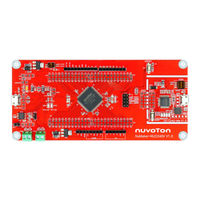
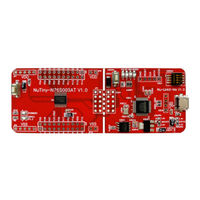
Arm 32-bit Cortex-M23 Microcontroller Evaluation Board for NuMicro M254/256/258 Series
Brand:
Nuvoton
| Category:
Motherboard
| Size: 5 MB
Table of Contents
Table of Contents
2
Overview
7
Figure 1-1 Numaker-M258KE Evaluation Board
7
Features
8
Hardware Configuration
9
Front View
9
Figure 3-1 Front View of Numaker-M258KE
9
Rear View
10
Figure 3-2 Rear View of Numaker-M258KE
10
Extension Connectors
11
3.3.1 Pin Assignment for Extension Connectors
11
Figure 3-3 M258KE3AE Extension Connectors
11
Table 3-1 Extension Connectors
11
Table 3-2 M258KE3AE Full-Pin Extension Connectors and GPIO Function List
15
3.3.2 Numaker-Tnlcdsub_M258K Compatible Extension Connectors
16
Table 3-3 Numaker-Tnlcdsub_M258K Extension Connectors and M258KE3AE Mapping GPIO List
17
3.3.3 Arduino uno Compatible Extension Connectors
18
Figure 3-4 Arduino uno Compatible Extension Connectors
18
Table 3-4 Arduino uno Extension Connectors and M258KE3AE Mapping GPIO List
19
Power Supply Configuration
20
VIN Power Source
20
Power Sources
20
Table 3-5 Vin Power Source
20
Table 3-6 5 V Power Sources
20
Power Sources
21
Power Connectors
21
Table 3-7 3.3 V Power Sources
21
Table 3-8 1.8 V Power Sources
21
Table 3-9 Power Connectors
21
USB Connectors
22
Power Switches
22
Power Supply Models
22
Figure 3-5 External Power Supply Sources on Nu-Link2-Me
22
Table 3-10 USB Connectors
22
Table 3-11 Power Switches
22
Figure 3-6 External Power Supply Sources on M258 Target Board
23
Table 3-12 Supply External Power through Nu-Link2-Me
23
Figure 3-7 Detach the Nu-Link2-Me from Numaker-M258KE
24
Table 3-13 Supply External Power for M258 Target Board
25
External Reference Voltage Connector
26
Battery Voltage (V BAT ) Connector
26
Ammeter Connector
26
Figure 3-8 Wiring between Ammeter Connector and Ammeter
26
Table 3-14 External Reference Voltage Connector
26
Table 3-15 Battery Voltage Connector
26
Table 3-16 Ammeter Connector
26
Touch Key
27
Push Buttons
27
3.10 Leds
27
Table 3-17 Touch Key
27
Table 3-18 Push-Buttons
27
Table 3-19 Leds
27
3.11 LCD Panel
28
Figure 3-9 LCD Digit Mapping Table
28
Table 3-20 LCD Specifications
28
Table 3-21 LCD Pin Mapping Table
29
3.12 Nu-Link2-Me
30
VCOM Switches
30
Table 3-21 VCOM Function of Nu-Link2-Me
30
Table 3-22 Operation Status LED Patterns
30
Quick Start
31
Toolchains Supporting
31
Nuvoton Nu-Link Driver Installation
31
Figure 4-1 Nu-Link USB Driver Installation Setup
31
Figure 4-2 Nu-Link USB Driver Installation
32
BSP Firmware Download
33
Hardware Setup
33
Figure 4-3 Open VCOM Function
33
Figure 4-4 ICE USB Connector
33
Figure 4-5 Device Manger
34
Figure 4-6 Putty Session Setting
34
Find the Example Project
35
Execute the Project under Toolchains
35
Keil MDK
35
Figure 4-7 Template Project Folder Path
35
Figure 4-8 Warning Message of "Device Not Found
35
Figure 4-9 Project File Migrate to Version 5 Format
36
Figure 4-10 Debugger Setting in Options Window
36
Figure 4-11 Programming Setting in Options Window
37
Figure 4-12 Compile and Download the Project
37
Figure 4-13 Keil MDK Debug Mode
38
Figure 4-14 Debug Message on Serial Port Terminal Windows
38
Iar Ewarm
39
Figure 4-15 IAR EWARM Window
39
Figure 4-16 Compile and Download the Project
39
Figure 4-17 IAR EWARM Debug Mode
40
Figure 4-18 Debug Message on Serial Port Terminal Windows
40
Nueclipse
41
Nuvoton NuMicro series User Manual (41 pages)
Brand:
Nuvoton
| Category:
Motherboard
| Size: 4 MB
Table of Contents
Table of Contents
2
Overview
6
Figure 1-1 Numaker-NUC240V Evaluation Board
6
Features
7
Hardware Configuration
8
Front View
8
Figure 3-1 Front View of Numaker-NUC240V
8
Rear View
9
Figure 3-2 Rear View of Numaker-NUC240V
9
Extension Connectors
10
Pin Assignment for Extension Connectors
10
Figure 3-3 NUC240V Extension Connectors
10
Table 3-1 Extension Connectors
10
Table 3-2 NUC240V Full-Pin Extension Connectors and GPIO Function List
13
Arduino uno Compatible Extension Connectors
14
Figure 3-4 Arduino uno Compatible Extension Connectors
14
Table 3-3 Arduino uno Extension Connectors and NUC240V Mapping GPIO List
15
Power Supply Configuration
16
VIN Power Source
16
Power Sources
16
Table 3-4 Vin Power Source
16
Table 3-5 5 V Power Sources
16
Power Sources
17
Power Connectors
17
Table 3-6 3.3 V Power Sources
17
Table 3-7 1.8 V Power Sources
17
Table 3-8 Power Connectors
17
USB Connectors
18
Power Switches
18
Power Supply Models
18
Figure 3-5 External Power Supply Sources on Nu-Link2-Me
18
Table 3-9 USB Connectors
18
Table 3-10 Power Switches
18
Figure 3-6 External Power Supply Sources on NUC240V Target Board
19
Table 3-11 Supply External Power through Nu-Link2-Me
19
Figure 3-7 Detach the Nu-Link2-Me from Numaker-NUC240V
20
Table 3-12 Supply External Power for NUC240V Target Board
21
External Reference Voltage Connector
22
Ammeter Connector
22
Figure 3-8 Wiring between Ammeter Connector and Ammeter
22
Figure 3-9 Project Path of Sys_Powerdown_Mincurrent
22
Table 3-13 External Reference Voltage Connector
22
Table 3-14 Ammeter Connector
22
Push Buttons
23
Leds
23
Nu-Link2-Me
23
VCOM Switches
23
Table 3-15 Push Buttons
23
Table 3-16 Leds
23
Table 3-17 VCOM Function of Nu-Link2-Me
23
Status Leds
24
3.10 CAN Bus Interface
24
Table 3-18 Operation Status LED Patterns
24
Table 3-19 CAN Bus Interface
24
Table 3-20 U10 Pin Connection
25
Table 3-21 U12 Pin Connection
25
Quick Start
26
Toolchains Supporting
26
Nuvoton Nu-Link Driver Installation
26
Figure 4-1 Nu-Link USB Driver Installation Setup
26
Figure 4-2 Nu-Link USB Driver Installation
27
BSP Firmware Download
28
Hardware Setup
28
Figure 4-3 Open VCOM Function
28
Figure 4-4 ICE USB Connector
28
Figure 4-5 Device Manger
29
Figure 4-6 Putty Session Setting
29
Find the Example Project
30
Execute the Project under Toolchains
30
Keil MDK
30
Figure 4-7 Template Project Folder Path
30
Figure 4-8 Warning Message of "Device Not Found
30
Figure 4-9 Project File Migrate to Version 5 Format
31
Nuvoton NuMicro series User Manual (41 pages)
Evaluation Board for NuMicro® 8051 Series
Brand:
Nuvoton
| Category:
Motherboard
| Size: 3 MB
Table of Contents
Table of Contents
2
Overview
6
Figure 1-1 Numaker-MUG51TB Evaluation Board
6
Features
7
Hardware Configuration
8
Front View
8
Figure 3-1 Front View of Numaker-MUG51TB
8
Rear View
9
Figure 3-2 Rear View of Numaker-MUG51TB
9
Extension Connectors
10
Pin Assignment for Extension Connectors
10
Figure 3-3 MUG51TB Extension Connectors
10
Table 3-1 Extension Connectors
10
Table 3-2 MUG51TB Full-Pin Extension Connectors and GPIO Function List
11
Arduino uno Compatible Extension Connectors
12
Figure 3-4 Arduino uno Compatible Extension Connectors
12
Table 3-3 Arduino uno Extension Connectors and MUG51TB9AE Mapping GPIO List
13
Power Supply Configuration
14
VIN Power Source
14
Power Sources
14
Table 3-4 Vin Power Source
14
Table 3-5 5 V Power Sources
14
Power Sources
15
Power Connectors
15
Table 3-6 3.3 V Power Sources
15
Table 3-7 1.8 V Power Sources
15
Table 3-8 Power Connectors
15
USB Connectors
16
Power Switches
16
Power Supply Models
16
Figure 3-5 External Power Supply Sources on Nu-Link2-Me
16
Table 3-9 USB Connectors
16
Table 3-10 Power Switches
16
Figure 3-6 External Power Supply Sources on MUG51TB Target Board
17
Table 3-11 Supply External Power through Nu-Link2-Me
17
Figure 3-7 Detach the Nu-Link2-Me from Numaker-MUG51TB
18
Table 3-12 Supply External Power for MUG51TB Target Board
19
External Reference Voltage Connector
20
Table 3-13 External Reference Voltage Connector
20
Ammeter Connector
21
Figure 3-8 Wiring between Ammeter Connector and Ammeter
21
Figure 3-9 Project Path of Powerdown_Boddisable
21
Table 3-14 Ammeter Connector
21
Push Buttons
22
Table 3-15 Push Buttons
22
Leds
23
Table 3-16 Leds
23
Nu-Link2-Me
24
VCOM Switches
24
Status Leds
24
Table 3-17 VCOM Function of Nu-Link2-Me
24
Table 3-18 Operation Status LED Patterns
24
Quick Start
25
Toolchains Supporting
25
Nuvoton Nu-Link Driver Installation
26
Figure 4-1 Nu-Link USB Driver Installation Setup
26
Figure 4-2 Nu-Link USB Driver Installation
27
BSP Firmware Download
28
Hardware Setup
28
Figure 4-3 Open VCOM Function
28
Figure 4-4 ICE USB Connector
28
Figure 4-5 Device Manger
29
Figure 4-6 Putty Session Setting
29
Find the Example Project
30
Execute the Project under Toolchains
30
Keil MDK
30
Figure 4-7 Template Project Folder Path
30
Figure 4-8 Warning Message of "Device Not Found
30
Figure 4-9 Project File Migrate to Version 5 Format
31
Figure 4-10 Debugger Setting in Options Window
31
Nuvoton NuMicro series User Manual (43 pages)
ARM Cortex-M0 32-bit Microcontroller
Brand:
Nuvoton
| Category:
Motherboard
| Size: 2 MB
Table of Contents
Table of Contents
2
1 Overview
3
2 Features
4
3 Introduction to Numaker uno Development Board
5
3.1 Numaker uno Jumper Description
7
Pin Assignment for NUC131SD2AE Extended Connectors
8
Numaker uno NUC131SD2AE Extended Connectors Layout
9
Arduino uno Pin Assignment for Numaker uno
10
Numaker uno Arduino Layout
11
Numaker uno PCB Placement
12
4 Downloading and Installing Arduino Ide 1.8.5 and Numaker uno Software
13
Downloading and Installing Arduino IDE 1.8.5 Software
13
Installing Nu-Link USB Driver for Arduino IDE 1.8.5
16
Hardware Setup
20
Testing USB and VCOM Device in the Device Manager
20
5 Starting to Use Numaker uno on Arduino Ide 1.8.5
21
Compiling and Executing Example Program
21
6 STARTING to USE NUMAKER uno on KEIL Μvision
26
Ide
26
Downloading and Installing Keil Μvision
26
IDE Software
26
Downloading and Installing Nu-Link Keil Driver
26
Hardware Setup
26
Procedure for Downloading and Debugging Example Program
26
7 Starting to Use Numaker uno on Iar Embedded Workbench
33
Downloading and Installing IAR Embedded Workbench Software
33
Downloading and Installing Nu-Link IAR Driver
33
Hardware Setup
33
Procedure for Downloading and Debugging Example Program
33
8 Downloading Nu-Link Driver from Nuvoton Website
36
Downloading and Installing Nu-Link Keil Driver
36
Downloading and Installing Nu-Link IAR Driver
38
9 Numaker uno Schematics
40
Numaker uno I/O Schematic
40
Numaker uno NUC131SD2AE Schematic
41
Nu-Link-Me Schematic
42
10 Revision History
43
Nuvoton NuMicro series User Manual (37 pages)
ARM Cortex-M 32-bit Microcontroller
Brand:
Nuvoton
| Category:
Motherboard
| Size: 1 MB
Table of Contents
Table of Contents
2
1 Overview
4
2 Nutiny-Sdk-Nuc029Sge Introduction
5
Nutiny-SDK-NUC029SGE Jumper Description
6
Power Setting
6
Debug Connector
6
USB Connector
6
Extended Connector
6
Reset Button
6
Power Connector
6
VCOM Enable
6
Pin Assignment for Extended Connector
8
Nutiny-SDK-NUC029SGE PCB Placement
20
3 How to Start Nutiny-SDK-NUC029SGE on the Keil Mdk ENVIRONMENT
21
Downloading and Installing Keil MDK Software
21
Downloading and Installing Nuvoton Nu-Link Driver
21
Hardware Setup
21
Downloading and Installing IAR Embedded Workbench Software
23
Downloading and Installing Nuvoton Nu-Link Driver
23
Example Program
21
4 How to Start Nutiny-SDK-NUC029SGE on the IAR Embedded Workbench
23
Hardware Setup
23
Downloading and Installing VCOM Driver
25
Development Tool Setup
27
Check the Using UART on the Keil Μvision IDE
27
Check the Target Device and Debug Setting
28
Build and Download Code to Nutiny-SDK-NUC029SGE
30
Open the Serial Port Terminal
30
Reset Chip
31
Example Program
23
5 Starting to Use Nu-Link-Me 3.0 VCOM Function
25
6 Nutiny-SDK-NUC029SGE Schematics
32
VCOM Mode Setting on Nutiny-SDK-NUC029SGE
27
Nu-Link-Me V3.0 Schematic
32
GPIO for 64 Pin Schematic
33
SDK Circuit Schematic
34
Target Chip
35
7 Revision History
36
Nuvoton NuMicro series User Manual (24 pages)
1T 8051-based Microcontroller
Brand:
Nuvoton
| Category:
Microcontrollers
| Size: 2 MB
Table of Contents
Table of Contents
2
Overview
5
Features
6
Hardware Configuration
7
Front View
7
Virtual COM Port Switch Description
7
Figure 3.1-1 Nutiny-N76S003AT (PCB Board)
7
Nutiny-N76S003AT Power Setting and Connector
8
Power Setting
8
Debug Connector
8
ICE USB Connector
8
Extended Connector
8
Reset Button
8
Power Connector
8
Virtual COM Port Function Switch
8
Pin Assignment for Extended Connector
8
Quick Start
10
Toolchains Supporting
10
Nuvoton Nu-Link Driver Installation
10
Figure 4.2-1 Nu-Link USB Driver Installation Setup
10
Figure 4.2-2 Nu-Link USB Driver Installation
11
BSP Firmware Download
12
Hardware Setup
12
Figure 4.4-1 Open VCOM Function
12
Figure 4.4-2 ICE USB Connector
12
Find the Example Project
13
Figure 4.4-3 Device Manger
13
Figure 4.4-4 Putty Session Setting
13
Execute the Project under Toolchains
14
Keil MDK
14
Figure 4.5-1 Template Project Folder Path
14
Figure 4.6-1 Warning Message of "Device Not Found
14
Figure 4.6-2 Project File Migrate to Version 5 Format
15
Figure 4.6-3 Debugger Setting in Options Window
15
Figure 4.6-4 Programming Setting in Options Window
16
Figure 4.6-5 Compile and Download the Project
16
Figure 4.6-6 Keil MDK Debug Mode
17
Figure 4.6-7 Debug Message on Serial Port Terminal Windows
17
Iar Ewarm
18
Figure 4.6-8 IAR EWARM Window
18
Figure 4.6-9 Compile and Download the Project
18
Figure 4.6-10 IAR EWARM Debug Mode
19
Figure 4.6-11 Debug Message on Serial Port Terminal Windows
19
Nutiny-N76S003At Schematics
20
Nu-Link2-Me
20
Figure 5.1-1 Nu-Link2-Me Circuit
20
Nutiny-N76S003AT Schematics
21
PCB Placement
21
Figure 5.2-1 N76S003AT20 Target Board Circuit
21
Figure 5.3-1 Front Placement
21
Figure 5.3-2 Rear Placement
22
Revision History
23
Nuvoton NuMicro series User Manual (38 pages)
ARM Cortex-M 32-bit Microcontroller
Brand:
Nuvoton
| Category:
Microcontrollers
| Size: 1 MB
Table of Contents
Table of Contents
2
Overview
4
Nutiny-Sdk-M0564 Introduction
5
Nutiny -SDK-M0564 Jumper Description
6
Power Setting
6
Debug Connector
6
USB Connector
6
Extended Connector
6
Reset Button
6
Power Connector
6
Virtual COM Port Function Switch
6
Pin Assignment for Extended Connector
8
Nutiny-SDK-M0564 PCB Placement
24
How to Start Nutiny-SDK-M0564 on the Keil Μvision IDE
25
Keil Uvision
25
IDE Software Download and Install
25
Nuvoton Nu-Link Driver Download and Install
25
Hardware Setup
25
Example Program
26
How to Start Nutiny-SDK-M0564 on the IAR Embedded Workbench
27
IAR Embedded Workbench Software Download and Install
27
Nuvoton Nu-Link Driver Download and Install
27
Hardware Setup
27
Example Program
28
Starting to Use Nu-Link-Me 3.0 VCOM Function
29
Downloading and Installing VCOM Driver
29
VCOM Mode Setting on Nutiny-SDK-M0564
30
Setup on the Development Tool
30
Check the Using UART on the Keil Μvision IDE
30
Check the Target Device and Debug Setting
31
Build and Download Code to Nutiny-SDK-M0564
33
Open the Serial Port Terminal
33
Reset Chip
33
Nutiny-SDK-M0564 Schematic
35
Nutiny-EVB-M0564 Schematic
35
Nuvoton NuMicro series User Manual (31 pages)
Arm Cortex-M 32-bit Microcontroller, NuMaker NuMicroPy
Brand:
Nuvoton
| Category:
Microcontrollers
| Size: 1 MB
Table of Contents
Table of Contents
2
1 Overview
4
2 Numicropy Introduction
5
Repl
5
Embedded Flash Partition
5
Modules and I/O Classes Support List
6
3 How to Start Numicropy
9
Nuvoton Nu-Link Driver Download and Install
9
Hardware Setup Steps
9
Burn Firmware
10
Python Code Update Steps
11
4 How to Customize Micropython Firmware
13
Packages Requirement
13
Install GNU Arm Toolchain
13
Build Firmware
13
Enable/Disable Module
13
Enable/Disable I/O Class
15
5 O Class Quick Reference
17
LAN Class
17
Pin Class
17
ADC Class
19
SPI Class
19
I 2 C Class
20
RTC Class
21
UART Class
21
CAN Class
22
USB HID Class
23
USB VCP Class
23
LED Class
24
Switch Class
24
Timer Class
24
PWM Class
25
WDT Class
28
Accel Class
28
Gyro Class
28
Mag Class
28
6 Summary
29
7 Revision History
30
Nuvoton NuMicro series User Manual (28 pages)
Brand:
Nuvoton
| Category:
Microcontrollers
| Size: 1 MB
Table of Contents
Table of Contents
2
1 Overview
4
2 Nutiny-Sdk-Nuc029Sde Introduction
5
Nutiny-SDK-NUC029SDE Jumper Description
6
Power Setting
6
Debug Connector
6
USB Connector
6
Extended Connector
6
Reset Button
6
Power Connector
6
VCOM Enable
6
Pin Assignment for Extended Connector
8
Nutiny-SDK-NUC029SDE PCB Placement
11
3 How to Start Nutiny-SDK-NUC029SDE on the Keil Mdk ENVIRONMENT
12
Downloading and Installing Keil MDK Software
12
Downloading and Installing Nuvoton Nu-Link Driver
12
Hardware Setup
12
Downloading and Installing IAR Embedded Workbench Software
14
Downloading and Installing Nuvoton Nu-Link Driver
14
Example Program
12
4 How to Start Nutiny-SDK-NUC029SDE on the IAR Embedded Workbench
14
Hardware Setup
14
Downloading and Installing VCOM Driver
16
Development Tool Setup
18
Check the Using UART on the Keil Μvision IDE
18
Check the Target Device and Debug Setting
19
Build and Download Code to Nutiny-SDK-NUC029SDE
21
Open the Serial Port Terminal
21
Reset Chip
22
Example Program
14
5 Starting to Use Nu-Link-Me 3.0 VCOM Function
16
6 Nutiny-SDK-NUC029SDE Schematics
23
VCOM Mode Setting on Nutiny-SDK-NUC029SDE
18
Nu-Link-Me V3.0 Schematic
23
GPIO for 64 Pin Schematic
24
SDK Circuit Schematic
25
Target Chip
26
7 Revision History
27
Nuvoton NuMicro series User Manual (26 pages)
RMCortex-M 32-bit Microcontroller
Brand:
Nuvoton
| Category:
Microcontrollers
| Size: 1 MB
Table of Contents
Table of Contents
3
1 Overview
5
2 Nutiny-Sdk-Nuc240 Introduction
6
Nutiny-SDK-NUC240 Jumper Description
7
Power Setting
7
Debug Connector
7
USB Connector
7
Extended Connector
7
Reset Button
7
Power Connector
7
VCOM Enable
7
Pin Assignment for Extended Connector
9
Nutiny-SDK-NUC240 PCB Placement
11
3 How to Start Nutiny-SDK-NUC240 on the Keil Μvision
12
Hardware Setup
12
Ide
12
Keil Uvision ® IDE Software Download and Install
12
Nuvoton Nu-Link Driver Download and Install
12
Example Program
13
4 How to Start Nutiny-SDK-NUC240 on the IAR Embedded Workbench
14
Hardware Setup
14
IAR Embedded Workbench Software Download and Install
14
Nuvoton Nu-Link Driver Download and Install
14
Example Program
15
5 Starting to Use Nu-Link-Me 3.0 VCOM Function
16
Downloading and Installing VCOM Driver
16
Setup on the Development Tool
17
Check the Using UART on the Keil Μvision IDE
17
Check the Target Device and Debug Setting
17
Build and Download Code to Nutiny-SDK-NUC240
19
Open the Serial Port Terminal
20
Reset Chip
20
6 Nutiny-SDK-NUC240 Schematic
22
VCOM Mode Setting on Nutiny-SDK-NUC240
17
Nutiny-EVB-NUC240 Schematic
22
GPIO for 100 Pin Schematic
23
SDK Circuit Schematic
24
Nu-Link-Me V3.0 Schematic
25
7 Revision History
26
Nuvoton NuMicro series User Manual (30 pages)
Arm Cortex-M 32-bit Microcontroller
Brand:
Nuvoton
| Category:
Motherboard
| Size: 1 MB
Table of Contents
Table of Contents
2
1 Overview
4
2 Nutiny-Sdk-M4521 Introduction
5
Nutiny -SDK-M4521 Jumper Description
6
Power Setting
6
Debug Connector
6
USB Connector
6
Extended Connector
6
Reset Button
6
Power Connector
6
Virtual COM Port Function Switch
6
Pin Assignment for Extended Connector
8
Nutiny-SDK-M4521 PCB Placement
16
3 How to Start Nutiny-SDK-M4521 on the Keil Μvision IDE
17
Hardware Setup
17
Keil Uvision
17
IDE Software Download and Install
17
Nuvoton Nu-Link Driver Download and Install
17
Example Program
18
4 How to Start Nutiny-SDK-M4521 on the IAR Embedded Workbench
19
Hardware Setup
19
IAR Embedded Workbench Software Download and Install
19
Nuvoton Nu-Link Driver Download and Install
19
Example Program
20
5 Starting to Use Nu-Link-Me 3.0 VCOM Function
21
Downloading and Installing VCOM Driver
21
Setup on the Development Tool
22
Check the Using UART on the Keil Μvision IDE
22
Check the Target Device and Debug Setting
23
Build and Download Code to Nutiny-SDK-M4521
25
Open the Serial Port Terminal
25
Reset Chip
25
6 Nutiny-SDK-M4521 Schematic
27
VCOM Mode Setting on Nutiny-SDK-M4521
22
Nutiny-EVB-M4521 Schematic
27
Nuvoton NuMicro series User Manual (33 pages)
ARM Cortex-M32-bit Microcontroller
Brand:
Nuvoton
| Category:
Motherboard
| Size: 3 MB
Table of Contents
Table of Contents
2
1 Overview
3
Features
3
2 Introduction to Numaker Uni
4
3 Introduction to Nu-Link Mini
5
4 Hardware Introduction
6
On-Board Devices Interface
6
Board Extension Interfaces
7
5 How to Start Numaker Uni on Ide
10
Supported IDE Software
10
Nuvoton Nu-Link Driver Download and Installation
10
Hardware Setup
12
Starting to Use Numaker Uni
12
Software Download
14
Folder Structure
16
Using Keil Μvision IDE to Program
17
Using IAR Embedded Workbench to Program
19
6 Sample Code Description
21
Application Project Examples
23
Numaker Uni Components and Socket Pins Test
23
Using Numaker Uni to Detect Temperature and Humidity
24
6.1.3 Using Numaker Uni to Receive Information from Numaker Uni APP
27
7 Revision History
32
Nuvoton NuMicro series Quick Start Manual (15 pages)
AliOS Things Arm Cortex-M 32-bit Microcontroller
Brand:
Nuvoton
| Category:
Motherboard
| Size: 1 MB
Table of Contents
Table of Contents
2
1 Overview
3
2 Requirements
4
Software Requirements
4
Hardware Requirements
4
3 Get Alios Things Sdk
5
Use Git Software
5
Download from Github Website
5
4 Alios Things Mqttapp Sample
6
Build Mqttapp Project
6
Burn Firmware
7
Numicro MCU Virtual Disk
7
Drag and Drop
8
Test Wi-Fi Local Connectivity
9
Test Ali-Cloud Service
10
5 Conclusion
13
6 Revision History
14
Advertisement
Related Products
Nuvoton NuMicro Family
Nuvoton NuMicro Nu-Link-Gang
Nuvoton NuMicro ISP
Nuvoton NuMicro NUC472 Series
Nuvoton NuMaker-M2351SF
Nuvoton NuMicro NuMaker-M032KI
Nuvoton NuMaker-MS51PC
Nuvoton NuMaker-ML51SD
Nuvoton ARM NuMaker-emWin-RDK-N9H20
Nuvoton NuMicro NuMaker-PFM-M487KM
Nuvoton Categories
Motherboard
Microcontrollers
Computer Hardware
Amplifier
Computer Accessories
More Nuvoton Manuals
Login
Sign In
OR
Sign in with Facebook
Sign in with Google
Upload manual
Upload from disk
Upload from URL