Advertisement
Quick Links
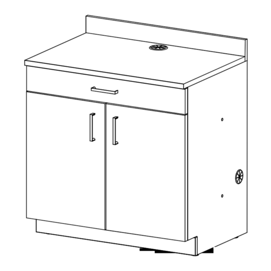
H-7876
BREAKROOM CABINET
TOOL NEEDED
Phillips
Screwdriver
P
PARTS
#
DESCRIPTION
A
Top Panel
B
Bottom Panel
C
Left Side Panel
D
Right Side Panel
E
Lower Back Panel
F
Upper Back Panel
G
Toe Kick Panel
H
Cross Support Panel
I
Backsplash Panel
PAGE 1 OF 8
1-800-295-5510
uline.com
Two Person Assembly
Recommended
A
C
H
L
J
G
B
QTY.
1
1
1
1
1
1
1
1
1
PARTS
N
O
R
PARTS
#
DESCRIPTION
J
Outer Front Drawer Panel
K
Inner Front Drawer Panel
L
Left Side Drawer Panel
M
Right Side Drawer Panel
N
Back Drawer Panel
O
Bottom Drawer Panel
P
Left Door
Q
Right Door
R
Shelf
I
D
F
M
E
Q
QTY.
1
1
1
1
1
1
1
1
1
0224 IH-7876
Advertisement

Subscribe to Our Youtube Channel
Related Manuals for U-Line H-7876


Summary of Contents for U-Line H-7876
- Page 1 H-7876 1-800-295-5510 uline.com BREAKROOM CABINET TOOL NEEDED Two Person Assembly Phillips Recommended Screwdriver PARTS PARTS PARTS DESCRIPTION QTY. DESCRIPTION QTY. Top Panel Outer Front Drawer Panel Bottom Panel Inner Front Drawer Panel Left Side Drawer Panel Left Side Panel Right Side Drawer Panel...
- Page 2 HARDWARE Cam Lock x 18 Cam Lock Post x 18 Dowel x 22 Leveler Bracket x 4 #8 x 1/2" Screw x 28 Drawer Slide Pack x 1 5 x 40 mm Screw x 16 1/4"-20 x 1" Screw x 2 Handle x 3 Hinge Mounting Hinge Arm x 4...
- Page 3 ASSEMBLY NOTE: Assemble unit on a smooth, non-marring 3. Extend slide on slide pack (X), push release lever surface to prevent scratching. Check that all down and pull slide apart. Repeat for other slide. parts are included. (See Figure 3) Insert six cam lock posts (T) into underside of Figure 3 top panel (A) and tighten.
- Page 4 ASSEMBLY CONTINUED 5. Install two leveler brackets (V) with threads at bottom 8. Insert two cam locks (S) and four dowels (U) into into left side panel using four #8 x 1/2" screws (W) on lower back panel (E). Repeat for upper back panel each leveler.
- Page 5 ASSEMBLY CONTINUED 11. Attach bumpers (DD) to top corners of 14. Attach handle to left door (P) using two outer front drawer panel (J). (See Figure 10) #8-32 x 1" screws (AA). Install two hinge arms (CC) into left door using two #6 x 1/2" screws (LL) on each 12.
- Page 6 ASSEMBLY CONTINUED 15. Assemble bottom panel (B), lower back panel (E), 17. Install top panel (A) and tighten all cam locks. upper back panel (F) and cross support panel (H) Secure top panel to cross support panel using onto right side panel (D). Attach left side panel (L) two #8 x 1¼"...
- Page 7 ASSEMBLY CONTINUED 19. Insert drawer assembly half slides into cabinet 21. Install door hinge arms into hinge mounting plates. assembly half slides and close drawer. (See Figure 17) Adjust hinges by tightening and loosening screws on hinge arms to move doors. (See Figure 19) Figure 17 Figure 19 20.
- Page 8 ASSEMBLY CONTINUED 23. Insert large grommet (GG) into hole in top panel. Figure 21 Insert small grommets (HH) into holes in side panels. Insert hole plugs (II) into holes in left and right side panels. (See Figure 21) 24. If ganging cabinets together, insert binding barrels (JJ) into holes on inner side panel of left cabinet and secure with 1/4"-20 x 1/2"...
Need help?
Do you have a question about the H-7876 and is the answer not in the manual?
Questions and answers