
Related Manuals for Solax TRIPLE POWER T-BAT-SYS-HV-S25


Summary of Contents for Solax TRIPLE POWER T-BAT-SYS-HV-S25
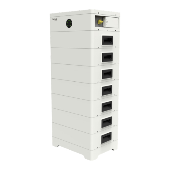
- Page 1 T-BAT-SYS-HV-S25 T-BAT-SYS-HV-S36 User Manual Version 3.0 www.solaxpower.com eManual in the QR code or at http://kb.solaxpower.com/...
- Page 3 CHNAGE HISTORY Changes between document versions are cumulative. The latest version contains all updates made in previous versions. Version 00 (Jan. 30, 2023) Initial release Version 01 (Jul. 27, 2023) Updated 3.1 Dimensions and Weight (change of the weight of battery module) Updated 4.4.3 Accessory (change of the packing list) Updated 6.3 Cable Connection (added installation steps of cover plate) Updated 7.3 Status Indicators (change of the figure of indicators)
-
Page 4: Table Of Contents
Content 1 Note on this Manual ..................1 1.1 Scope of Validity ....................1 1.2 Target Group ....................1 1.3 Symbols......................1 2 Safety ........................2 2.1 Safety Instruction ...................2 2.1.1 General Safety Precautions ..............2 2.1.2 Explanation of Labels ................3 2.2 Response to Emergency Situations ............4 2.2.1 Leaking Batteries ...................4 2.2.2 Fire ......................4 2.2.3 Wet Batteries and Damaged Batteries ..........4... - Page 5 6.2 Communication Connection (connecting to inverter) ......32 6.3 Cable Connection ..................33 6.3.1 Wiring without Series Box ..............33 6.3.2 Wring with Series Box ................36 7 Commissioning ....................40 7.1 DIP Switch ......................40 7.2 Start and Shutdown Procedure ..............41 7.2.1 Unlockable Switch .................41 7.2.2 Lockable Switch ..................42 7.3 Status Indicators .....................44 8 Troubleshooting ....................
-
Page 7: Note On This Manual
1 Note on this Manual 1 Note on this Manual 1.1 Scope of Validity This manual, an integral part of T-BAT Series, contains information on assembly, commissioning, maintenance and failure of the device. Please read it carefully before operation. TBMS-MCS0800 Battery Module TP-HS25, TP-HS36 Note: In case of one tower, there are 3 parts of the T-BAT system, which includes... -
Page 8: Safety
2 Safety 2 Safety 2.1 Safety Instruction For safety reasons, installers are responsible for familiarizing themselves with the contents of the Manual and all Warnings before performing installation. 2.1.1 General Safety Precautions WARNING! Do not crush or impact battery, and always dispose of it according to relevant safety regulations. -
Page 9: Explanation Of Labels
2 Safety 2.1.2 Explanation of Labels Label Explanation CE mark for conformity TUV certification The battery system must be disposed of at a proper facility for environmentally-safe recycling. Do not dispose of the battery together with household waste. Do not dispose of the battery together with household waste. Read the enclosed documentation. -
Page 10: Response To Emergency Situations
Do not touch the battery module after being wet from and soaked in the water. Do not use the battery module if it is damaged. Otherwise, the loss to life and property will be caused. Please pack the battery in its original packaging, and return it to SolaX or the distributor. WARNING! Damaged batteries may leak electrolyte or produce flammable gas. -
Page 11: Qualified Installer
2 Safety 2.3 Qualified Installer WARNING! All operations of T-BAT SYS-HV relating to electrical connection and installation must be carried out by qualified personnel. A skilled worker is defined as a trained and qualified electrician or installer who has all of the following skills and experience: Knowledge of the functional principles and operation of grid-tied systems;... -
Page 12: Production Information
3 Production Information 3 Production Information 3.1 Dimensions and Weight A battery management system (hereinafter referred to as BMS) is an electronic system that manages a rechargeable battery. A battery module is a type of electrical battery which can charge or discharge loads. - Page 13 3 Production Information Base 104.2 Series Box...
-
Page 14: Installation Space
3 Production Information 3.2 Installation Space One Tower > 100 mm > 400 mm > 400 mm Two towers > 100 mm > 100 mm > 400 mm > 400 mm 400 ~ 800 *Note: The above figures show an example of installation space of “One Tower“ and “Two Towers“. -
Page 15: Appearance
3 Production Information 3.3 Appearance ■ Left side view HEA T Item No. Description HEAT: Connect “HEAT“ port of Series Box (if any); or, the port must be connected to a short-circuit plug. *Note: The port has been insert the short-circuit plug before delivery, DO NOT remove it. - Page 16 3 Production Information Right side view SWITCH BAT+ BAT- POWER VIII Item No. Description POWER: Start system SWITCH: A switch for battery’s input and output VIII DIP: Realize battery’s parallel function (A reserved function) BAT+: Connect BMS’s BAT+ to inverter’s BAT+ BAT-: Connect BMS’s BAT- to inverter’s BAT- GND: Grounding port of BMS to inverter’s grounding port BMS: Connect the “BMS“...
- Page 17 3 Production Information Battery Module ■ The hot-plug interface is connected to the bot- tom of battery module or BMS. Bottom The hot-plug interface is connected to the top of battery module or Base. Base ■ The hot-plug interface is connected to the bottom of battery module.
- Page 18 3 Production Information Series Box ■ Left side view HEA T Item No. Description HEAT: Connect to the “HEAT“ port of BMS GND: Connect the grounding port to the grounding port of BMS B-: Connect to the ”B-” of BMS B+: Connect to the “B+“...
-
Page 19: Basic Features
3 Production Information 3.4 Basic Features 3.4.1 Features The T-BAT SYS-HV is one of the most advanced energy storage systems on the market today, using state-of-the-art technology, and having the characteristics of high reliability and convenient control. Characteristics are shown as follows: 90% DOD;... -
Page 20: Specification
3 Production Information 3.5 Specification 3.5.1 T-BAT-SYS-HV-S25 Configuration List ■ Nominal Operating Battery Model Energy Voltage Module (kWh) (Vdc) T-BAT HS5.0 TBMS-MCS0800 × 1 TP-HS25 × 2 5.12 90-116 T-BAT HS7.5 TBMS-MCS0800 × 1 TP-HS25 × 3 7.68 135-174 T-BAT HS10.0 TBMS-MCS0800 ×... - Page 21 3 Production Information Module T-BAT HS20.0 T-BAT HS22.2 T-BAT HS25.0 T-BAT HS27.5 T-BAT HS30.0 T-BAT HS32.5 Nominal Voltage (Vdc) 409.6 460.8 563.2 614.4 665.6 Operating Voltage (Vdc) 360-465 450-522 450-580 495-636 540-695 585-750 Nominal Capacity (Ah) 1 Nominal Energy (kWh) 1 20.48 23.04 25.60...
-
Page 22: T-Bat-Sys-Hv-S36
3 Production Information 3.5.2 T-BAT-SYS-HV-S36 Configuration List ■ Nominal Operating Battery Module Energy Voltage Module (kWh) (Vdc) T-BAT HS7.2 TBMS-MCS0800 × 1 TP-HS36 × 2 7.37 90-116 T-BAT HS10.8 TBMS-MCS0800 × 1 TP-HS36 × 3 11.06 135-174 T-BAT HS14.4 TBMS-MCS0800 × 1 TP-HS36 ×... - Page 23 3 Production Information Module T-BAT HS28.8 T-BAT HS32.4 T-BAT HS36.0 T-BAT HS39.6 T-BAT HS43.2 T-BAT HS46.8 Nominal Voltage (Vdc) 409.6 460.8 563.2 614.4 665.6 Operating Voltage (Vdc) 360-465 450-522 450-580 495-636 540-695 585-750 Nominal Capacity (Ah) 1 Nominal Energy (kWh) 1 29.49 33.18 36.86...
-
Page 24: Preparation Before Installation
4 Preparation before Installation 4 Preparation before Installation 4.1 Prerequisites When assembling the system, avoid touching the battery terminals with any metal object or bare hands. According to the design principles, T-BAT SYS-HV will provide a safe and reliable energy. Improper operation and equipment damage may cause overheating and electrolyte leakage. -
Page 25: Safety Gear
4 Preparation before Installation 4.2 Safety Gear Installation and maintenance personnel must operate according to applicable federal, state, and local regulations as well as industry standards regarding product installation. Personnel must wear safety gear as indicated below in order to avoid short circuit and personal injury. Anti-dust mask Safety boots Safety gloves... -
Page 26: Preparation
4 Preparation before Installation 4.4 Preparation 4.4.1 Check for Transport Damage Ensure that the battery is intact during and after transportation. If there are damages, such as cracks, please contact your dealer immediately. 4.4.2 Unpacking Remove the packing tape on the carton to open the battery package. Ensure that the battery modules and relevant items are complete. -
Page 27: Accessory
4 Preparation before Installation 4.4.3 Accessory BMS (TBMS-MCS0800) Communication cable Power cable (orange) Base (BMS port) (2000 mm) (2000 mm)* M4*10 Phillips-head screw Power cable (Black) M4*14 Phillips-head screw L bracket Adjustable bracket (2000 mm)* M4*20 Phillips-head screw Expansion bolt RNB5-6 current terminal Washer M6 Flange nut... - Page 28 4 Preparation before Installation Battery module (TP-HS25/TP-HS36) M4×14 Phillips-head Screw Battery module Document Gasket Item No. Description Quantity (Unit: pc) Battery module (TP-HS25 or TP-HS36) M4×14 Phillips-head screw Gasket Document Series Box Grounding cable Communication cable Series Box Base (2200 mm) (COM port) (2200 mm) Power cable (orange) Power cable (black)
- Page 29 4 Preparation before Installation Item No. Description Quantity (Unit: pc) Series Box Base Grounding cable (2200 mm) Communication cable (COM port) (2200 mm) Heater cable (HEAT port) (2200 mm) Power cable (orange) (2300 mm) Power cable (black) (2250 mm) L bracket Adjustable bracket M4×10 Phillips-head screw M6 Flange nut...
-
Page 30: Equipment Installation
5 Equipment Installation 5 Equipment Installation 5.1 Installation Environment Requirements Ensure that the equipment is installed in a well ventilated environment; ■ To prevent fire due to high temperature, ensure that the ventilation vents or ■ heat dissipation system are not blocked when the equipment is running; Do not expose the equipment to flammable or explosive gas or smoke. -
Page 31: Installation Procedure
5 Equipment Installation 5.2 Installation Procedure *Note: 1. Up to 9 battery modules can be installed in one tower. If the battery module users purchased excesses 10 sets (including 10), a Series Box needs to be installed to connect two towers in series. 2. - Page 32 5 Equipment Installation Step 3. Place one battery module on the Base. Place battery module Remove the dust covers *Note: If the Base is shifted after placing battery module, move it to its original location according to the mark previously drawn. Step 4.
- Page 33 5 Equipment Installation Step 6. Join Adjustable bracket (Part E) and L bracket (Part D) with M6 Flange nuts (Part M) (× 2 pcs). Attach M6 Flange nuts but not tighten Step 7. Secure the assembled bracket on the battery module and wall. Attach the assembled bracket on the battery module with M4x10 Phillips-head screw (Part F) (×...
- Page 34 5 Equipment Installation Remove the assembled bracket; Insert Expansion bolt (Part I) (× 2 pcs) Remove bracket Secure the assembled bracket to the wall with Self-tapping screw (Part K) (× 2 pcs) and Washer (Part J) (× 2 pcs), and tighten them (Torque: 4 N·m); Secure the assembled bracket on the battery module with M4x10 Phillips-head screw (×...
- Page 35 5 Equipment Installation Step 8. Place BMS, and tighten M4x14 Phillips-head screw (Part G) (× 4 pcs) and gasket (Part N) (× 4 pcs) on both sides (Torque: 0.9 to 1.1 N·m) Torque: 0.9-1.1 N·m *Note: Regarding the cover plate on both sides of the BMS, they should be in- stalled after finishing wiring.
- Page 36 5 Equipment Installation Installation steps with Series Box In case of more than 10 sets of battery module (including 10), a Series Box needs to be installed to connect two towers in series, and an accessories kit for Series Box will not deliver for free. The installation procedure for these two towers is the same as that for one tower.
-
Page 37: Wiring
6 Wiring 6 Wiring Current terminal connection and communication cable, connecting BMS and inverter, shall be made before conducting wiring. 6.1 Current Terminal Connection The steps for making current terminal connection are shown as follows: Step 1. Strip the cable jacket about 8 to 10 mm from the end; Step 2. -
Page 38: Communication Connection (Connecting To Inverter)
6 Wiring 6.2 Communication Connection (connecting to inverter) To ensure normal operation of BMS and inverter, the BMS communication cable delivered with the BMS accessories kit is required to connect RJ45 connector. The specific definition of the communication cable is shown as follows: BMS_H BMS_L The wire sequence of one terminal connecting to the inverter is the same as the wire sequence of the other terminal, connecting to the BMS. -
Page 39: Cable Connection
6 Wiring 6.3 Cable Connection Before wiring, please: Step 1. Remove the screws on both covers of the BMS, Step 2. Press the cover; *Note: Remove the silicone sleeves from the ports of BMS and Series Box (if any). 6.3.1 Wiring without Series Box *Note: Please remove the labels attached to both cover plates before conducting wiring. - Page 40 6 Wiring Short-circuit Waterproof cap plug HEA T *Note: In case of one tower, a waterproof cap shall be put on the unconnected “COM” port, as well as a short-circuit plug on the unconnected “HEAT” port. Right side of BMS (BMS to inverter) Power cable (black) (Part C): Connect “BAT-”...
- Page 41 6 Wiring *Note: 1. Press and hold the White Lock Button while unplugging the power cable, or it cannot be pulled out. 2. Use the rotation wrench to tighten the communication cable, and remove it after tightening. Installation of Cover Plate After finishing wiring, there are two cover plates on both sides of the BMS that need to be secured with M4*20 Phillips-head screw (Part H) (×...
-
Page 42: Wring With Series Box
6 Wiring 6.3.2 Wring with Series Box Communication cable (Part B2): There are two terminals at both ends; one connects to “COM” port of BMS, and the other connects to “COM” port of Series Box. Heater cable (Part C2): There are two terminals at both ends; one connects to “HEAT”... - Page 43 6 Wiring Wiring between BMS and Series Box *Note: Please remove the labels attached to both cover plates before conducting wiring. Power Heater cable cable (red) (HEAT port) Communication cable (COM port) Grounding cable Rotation wrench (Part P2) Power cable (black) Communication cable (COM port) Heater cable (HEAT port)
- Page 44 6 Wiring Before wiring, the short-circuit plug on the HEAT port should be removed. And after finishing wiring, please make sure that the heater cable is locked. Rotate anti-clockwise to remove short-circuit plug Insert heater cable into HEAT port, and rotate clockwise to lock it. Align the groove according to the arrows.
- Page 45 7 Commissioning Right side of BMS Rotation wrench Power Here is the cable (red) white lock button Communication cable Regarding the white lock button, see the figure below. Here is the White white lock White lock button lock button button Power cable (black) Grounding cable *Note: 1.
-
Page 46: Commissioning
7 Commissioning 7 Commissioning 7.1 DIP Switch DIP Switch is equipped on BMS. See figure below. Description DIP switch 1 A reserved function DIP switch 2 A reserved function DIP switch 3 A reserved function Terminal resistance *Note: ■ The DIP switch 4 shall be flipped down (open the circuit) when DIP switch 4 connecting BMS to inverter;... -
Page 47: Start And Shutdown Procedure
7 Commissioning 7.2 Start and Shutdown Procedure The BMS is provided with two kinds of switches, unlockable or lockable version. Users may purchase it based on their location. 7.2.1 Unlockable Switch The unlockable switch (shown below) allows a user to rotate between two states, such as ON or OFF. -
Page 48: Lockable Switch
7 Commissioning Power off Step 1. Rotate the SWITCH to OFF state; Step 2. Press the POWER button for 1 second to shut down system. See figure below. OF F OF F OF F 7.2.2 Lockable Switch The lockable switch (shown below) allows a user to rotate among three states, such as ON, OFF or OFF+LOCK. - Page 49 7 Commissioning Power on Step 1. Rotate the SWITCH to ON; Step 2. Press the POWER button for more than 0.5 seconds to start system. See figure below. *Note: Frequently pressing the POWER button may cause a system error. ■ If the system does not start after pressing POWER button, please try again in ■...
-
Page 50: Status Indicators
7 Commissioning 7.3 Status Indicators The power indicators show the current battery percentage. There are five indicators on the BMS, one status light and four SOC power indicators. See figure below: For the derailed information on indicators, see the table below: Status Description After pressing the POWER button to start the system, the status light... - Page 51 7 Commissioning Table 1: Indicator information while charging SOC value Status light SOC1 SOC2 SOC3 SOC4 0% ≤ SOC < 25% Green Flash Light off Light off Light off SOC < 50% Green Light on Flash Light off Light off SOC <...
- Page 52 7 Commissioning The power indicators will change according to the actual situation, with details as below: Fault SOC1 SOC2 SOC3 SOC4 Huge differential pressure Flash Voltage fault (undervoltage and overvoltage of unit, overvoltage and Flash undervoltage of total voltage) Temperature fault (high temperature, low Flash Flash temperature)
-
Page 53: Troubleshooting
8 Troubleshooting 8 Troubleshooting Check the indicators (refer to the “7.3 Status Indicators“) to determine the status of T-BAT SYS-HV. In case the following circumstance occurs, for instance, voltage or temperature exceeding the limit, a warning state will be triggered. T-BAT system’s BMS will periodically report its operating state to inverter. - Page 54 8 Troubleshooting The temperature of BMS is too low. Low temperature Warm up BMS and restart; BMS_TemLow of BMS Contact the company’s after-sales personnel. Inconsistency of battery. Cell imbalance of Restart BMS; ■ BMS_CellImbalance ■ Contact the company’s after-sales personnel. Hardware protection of BMS.
- Page 55 8 Troubleshooting Software and Different type of BMS. hardware Restart BMS; ■ BMS_SW&HW_Unmatch mismatch ■ Contact the company’s after-sales error of BMS personnel. Different type of BMS. BMS and battery Restart BMS; ■ BMS_M&S_Unmatch module mismatch ■ Contact the company’s after-sales error personnel.
-
Page 56: Decommissioning
9 Decommissioning 9 Decommissioning 9.1 Dismantling Battery Shutting down battery unit: Disconnect the cables between BMS and inverter; ■ Disconnect the series wiring terminal on the battery; ■ Disconnect the cables. ■ 9.2 Packing Pack the BMS and battery module in the original packaging. If the original packaging is no longer available, use an equivalent carton or box that meets the following requirements: Suitable for loads over 70.00 kg;... -
Page 57: Maintenance
10 Maintenance 10 Maintenance If the ambient temperature for storage is -20°C~30°C, recharge the batteries ■ at least once every 12 months. If the ambient temperature for storage is 30°C~50°C, recharge the batteries at ■ least once every 6 months. If the battery(ies) has(have) not been used for more than 9 months, the bat- ■... -
Page 58: Disclaimer
11 Disclaimer 11 Disclaimer Triple Power protects the product under warranty when it is installed and used as listed in the Manual. Violation of the installation procedure or use of the product in any way not described in the Manual will immediately void all warranties on the product. - Page 59 SolaX Power Network Technology (Zhejiang) Co., Ltd. Add.: No. 288, Shizhu Road, Tonglu Economic Development Zone, Tonglu City, Zhejiang Province, 310000 P. R. CHINA Tel.: +86 (0) 571-56260011 E-mail: info@solaxpower.com / service@solaxpower.com Copyright © SolaX Power Technology (Zhejiang) Co., Ltd. All rights reserved. 320101057703...
Need help?
Do you have a question about the TRIPLE POWER T-BAT-SYS-HV-S25 and is the answer not in the manual?
Questions and answers