
Subscribe to Our Youtube Channel
Related Manuals for Sentera Controls HPSPM-LP


Summary of Contents for Sentera Controls HPSPM-LP
- Page 1 HPSPM-LP DIFFERENTIAL PRESSURE PI CONTROLLER FOR FANS Mounting and operating instructions...
-
Page 2: Table Of Contents
Table of contents SAFETY AND PRECAUTIONS PRODUCT DESCRIPTION ARTICLE CODES INTENDED AREA OF USE TECHNICAL DATA STANDARDS OPERATIONAL DIAGRAM WIRING AND CONNECTIONS MOUNTING INSTRUCTIONS IN STEPS VERIFICATION OF THE INSTALLATION INSTRUCTIONS OPERATING INSTRUCTIONS TRANSPORT AND STORAGE WARRANTY AND RESTRICTIONS MAINTENANCE... -
Page 3: Safety And Precautions
In case there are any questions that are not answered, please contact your technical support or consult a professional. MIW-HPSPM-LP-EN-000 - 24 / 05 / 2023 3 - 10 www.sentera.eu... -
Page 4: Product Description
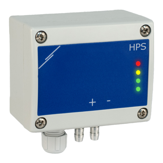
CONTROLLER FOR FANS PRODUCT DESCRIPTION The HPSPM-LP are high resolution differential pressure controllers (-125—125 Pa). The integrated PI control with anti-windup function offers the possibility to directly control EC motors / fans. They are equipped with a fully digital state-of-the-art pressure transducer designed for a wide range of applications. -
Page 5: Operational Diagram
Modbus RTU communication, signal /B Pin 6 Pin 7 Ground, supply voltage Pin 8 8 mm 8 mm 8 mm 8 mm 24 VDC MIW-HPSPM-LP-EN-000 - 24 / 05 / 2023 5 - 10 www.sentera.eu back to the table of contents... -
Page 6: Mounting Instructions In Steps
Insert the cable through the cable gland. Crimp the RJ45 cable and plug it into the socket, see Fig. 3 and section “Wiring and connections”. Fig. 3 Connections MIW-HPSPM-LP-EN-000 - 24 / 05 / 2023 6 - 10 www.sentera.eu back to the table of contents... - Page 7 Master Slave 1 Slave 2 Slave n NO T E On a Modbus RTU network, two bus terminators (NBTs) need to be activated. MIW-HPSPM-LP-EN-000 - 24 / 05 / 2023 7 - 10 www.sentera.eu back to the table of contents...
-
Page 8: Verification Of The Installation Instructions
After 2 seconds the green LED2 and yellow LED3 will blink twice once again to indicate that the calibration procedure has finished (see Fig. 7 Calibration Indication). MIW-HPSPM-LP-EN-000 - 24 / 05 / 2023 8 - 10 www.sentera.eu back to the table of contents... - Page 9 When the red LED4 is on, the differential pressure, air volume or air velocity has exceeded the minimum or maximum alarm threshold. MIW-HPSPM-LP-EN-000 - 24 / 05 / 2023 9 - 10 www.sentera.eu...
-
Page 10: Transport And Storage
In case of heavy pollution, clean with a non-aggressive product. In these circumstances the unit should be disconnected from the supply. Pay attention that no fluids enter the unit. Only reconnect it to the supply when it is completely dry. MIW-HPSPM-LP-EN-000 - 24 / 05 / 2023 10 - 10 www.sentera.eu...
Need help?
Do you have a question about the HPSPM-LP and is the answer not in the manual?
Questions and answers