SolaX Power X1-EVC Series User Manual
Hide thumbs
Also See for X1-EVC Series:
- Installation manual (74 pages) ,
- User manual (28 pages) ,
- Quick installation manual (2 pages)

Related Manuals for SolaX Power X1-EVC Series


Summary of Contents for SolaX Power X1-EVC Series
- Page 1 X1/X3-EVC 7.2 kW / 11 kW / 22 kW User Manual Version 2.0 www.solaxpower.com eManual in the QR code or at http://kb.solaxpower.com/...
- Page 3 No part of this manual may be reproduced, transmitted, transcribed, stored in a retrieval system, or translated into any language or computer language, in any form or by any means without the prior written permission of SolaX Power Technology (Zhejiang) Co., Ltd. Trademarks and other symbol or design (brand name, logo) that distinguishes the products or services offered by SolaX has been trademark protected.
- Page 4 About This Manual Scope of Validity This manual is an integral part of X1/X3-EVC Series EV-Charger. It describes the installation, electrical connection, commissioning, maintenance and troubleshooting of the product. Please read it carefully before operating. X1-EVC-7.2K(SXC) X1-EVC-7.2K(PXC) X3-EVC-11K(SXC) X3-EVC-11K(PXC) X3-EVC-22K(SXC) X3-EVC-22K(PXC) X1-EVC-7.2K(SLC) X1-EVC-7.2K(PLC)
- Page 5 Conventions The symbols that may be found in this manual are defined as follows. Symbol Description Indicates a hazardous situation which, if not avoided, DANGER will result in death or serious injury. Indicates a hazardous situation which, if not avoided, WARNING could result in death or serious injury.
-
Page 6: Table Of Contents
Table of Contents Safety ......................1 1.1 General Safety ........................1 1.2 Safety Instructions ......................1 Product Overview ..................3 2.1 System Description ......................3 2.2 Supported Power Grid .....................3 2.3 Appearance .........................4 2.3.1 Dimensions ......................6 2.3.2 LCD Panel .......................7 2.3.3 Symbols on the Label ..................8 2.4 Principle Circuit Diagram ....................9 2.5 Basic Features ........................10 Transportation and Storage ..............11... - Page 7 8.1.2 App Registration and Login ................38 8.2 Configuration ........................41 8.2.1 Add Device ......................41 8.2.2 Wi-Fi Connection ....................41 8.2.3 Local Mode ......................43 8.3 Settings for EV-Charger ....................44 8.3.1 Operation to Enter the Setting Page ..............44 8.3.2 Overview of the Setting Page ................47 Operation Method ...................49 9.1 States .............................49 9.2 Start-up Patterns ........................49...
-
Page 9: Safety
Safety General Safety The series EV-Charger has been meticulously designed and thoroughly tested to comply with all relevant state and international safety standards. Nevertheless, like all electrical and electronic equipment, safety precautions must be observed and followed during the installation of the EV-Charger to minimize the risk of personal injury and ensure a safe installation. - Page 10 Safety DANGER! • Danger to life due to output and input high voltages in this device. • Do not attempt to open the enclosure without authorization from SolaX. Unauthorized opening of the enclosure will void the warranty and can result in lethal danger or serious injury due to electric shock.
-
Page 11: Product Overview
Product Overview System Description The X1/X3-EVC series are AC EV charger and intended only for charging electric vehicles. It should be installed in a fixed location and connected to the AC supply. The EV-Charger can communicate with other devices or systems (inverter, meter, CT, third-party charger management platform, etc.) to realize intelligent control of charging process. -
Page 12: Appearance
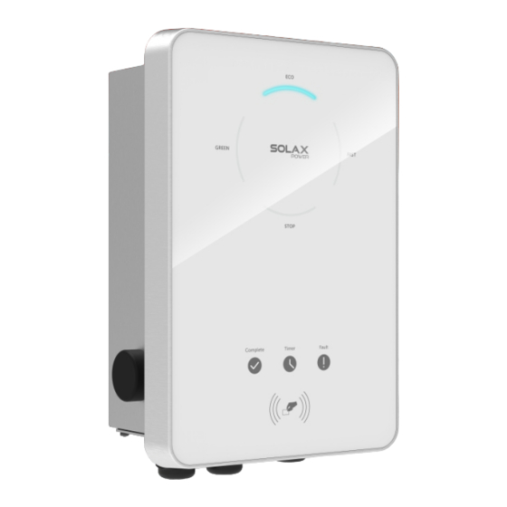
Product Overview Appearance EMERGENCY Type label STOP button panel Charging connector base Wiring connection area Figure 2-3 Apprearance of Socket Type Charging connetor EMERGENCY Type label STOP button panel Charging connector base Wiring connection area Figure 2-4 Apprearance of Plug Type... - Page 13 Product Overview Table 2-1 Desciption of appearance Item Description Type label clearly identifies the device type, serial number, specific Type label parameters, certification, etc. Including LED indicators, LCD screen (Optional) and card swiping position. LCD panel LED indicators indicate the operating status of the EV-Charger. LCD screen displays the information.
-
Page 14: Dimensions
Product Overview 2.3.1 Dimensions 249 mm 155 mm Figure 2-5 Dimensions of Socket Type 265 mm 155 mm Figure 2-6 Dimensions of Plug Type... -
Page 15: Lcd Panel
Product Overview 2.3.2 LCD Panel AVAILABLE COMPLETE PREPARING Operating status indicator light CHARGING LCD Screen (Optional) Unavailable Network Fault Unavailable indicator light Fault indicator light Network indicator light Card swiping position Figure 2-7 LCD Panel • In a normal state, the "AVAILABLE" light will be blue when the connector is not plugged and the "PREPARING"... -
Page 16: Symbols On The Label
Product Overview 2.3.3 Symbols on the Label Table 2-3 Description of symbols Symbol Description CE mark of conformity TUV certification UKCA mark of conformity Caution, risk of electric shock Caution, risk of danger The EV-Charger can be recycled. Do not dispose of the EV-Charger together with household waste. Used electrical devices must be collected separately and recycled in an environmentally responsible manner. -
Page 17: Principle Circuit Diagram
Product Overview Principle Circuit Diagram The principle design of the EV-Charger is shown in the figure below: Type A 30 mA + DC 6 mA OUTPUT-L3 INPUT-L3 INPUT-L2 OUTPUT-L2 Charging INPUT-L1 OUTPUT-L1 Plug/Socket INPUT-N OUTPUT-N Central Control Board * L2, L3 are for three-phase EV-Charger. PP is only for Socket Type. -
Page 18: Basic Features
Product Overview Basic Features The features of the series EV-Charger are listed as below. • Plug or socket outlet selectable • Integrated current failure monitoring (30 mA AC & 6 mA DC) • Encrypted communication based on TLS • Indoor and outdoor easy installation •... -
Page 19: Transportation And Storage
Transportation and Storage If the EV-Charger is not put into use immediately, the transportation and storage requirements needs to be met: Transportation • Observe the caution signs on the packaging of EV-Charger before transportation. • Pay attention to the weight of EV-Charger. Be cautious to avoid injury when carrying the EV-Charger. -
Page 20: Preparation Before Installation
Preparation before Installation Selection of Installation Location The installation location selected for the EV-Charger is quite critical in the aspect of the guarantee of device safety, service life and performance. • It has the IP65 ingress protection, which allows it to be installed outdoor; •... -
Page 21: Installation Carrier Requirement
Preparation before Installation 4.1.2 Installation Carrier Requirement The mounting location must be suitable for the weight and dimensions of the product and the support surface for installation must be made of a non-flammable material. • Solid brick/concrete, or mounting surface with equivalent strength; •... -
Page 22: Tools Requirement
Preparation before Installation Tools Requirement Installation tools include but are not limited to the following recommended ones. If necessary, use other auxiliary tools on site. Hammer drill Marker Measuring tape Utility knife Flat-head Crimping tool Cross screwdriver screwdriver Wire stripper for RJ45 Crimping tool for ferrules... -
Page 23: Additionally Required Materials
Preparation before Installation Additionally Required Materials Table 4-1 Additionally required Materials No. Required Material Type Type A RCD with a trip current of ≤ 30 mA; RCBO * 2P and rated current ≥ 40 A for 7 kW, 4P and rated current ≥... -
Page 24: Unpacking And Inspection
Unpacking and Inspection Unpacking • The EV-Charger undergoes 100% testing and inspection before shipping from the manufacturing facility. However, transport damage may still occur. Before unpacking the EV-Charger, please verify that the model and outer packing materials for damage, such as holes and cracks. •... -
Page 25: Scope Of Delivery
Unpacking and Inspection • Be careful when dealing with all package materials which may be reused for storage and relocation of the EV-Charger in the future. • Upon opening the package, check whether the appearance of the EV-Charger is damaged or lack of accessories. If any damage is found or any parts are missing, contact your dealer immediately. -
Page 26: Installation And Wiring
Installation and Wiring WARNING! • Only the qualified personnel can perform the mechanical installation following the local standards and requirements. • Check the existing power cables or other piping in the wall to prevent electric shock or other damage. CAUTION! •... -
Page 27: Decide Application Scenario
Installation and Wiring Decide Application Scenario The EV-Charger offers different application scenarios and the communication connection is different under different application scenario. Please decide the application scenarios before installation. Home Scene • Communication with CT/Meter The EV-Charger can work with the inverter system which does not support communication with it to form an intelligent photovoltaic, storage and EV charging energy system. - Page 28 Installation and Wiring • Communication with Inverter The EV-Charger can work with the inverter system which supports communication with it to form an intelligent photovoltaic, storage and EV charging energy system. Through communicating with the inverter, the EV-Charger can obtain the current information of the grid and PV and realize the smart control of different charging modes.
- Page 29 Installation and Wiring OCPP Scene The EV-Charger can be connected with the OCPP server and controlled by the OCPP server. Grid Electricity distribution meter, bidirectional EV-Charger OCPP1.6 RCBO Meter Figure 6-5 OCPP scene...
-
Page 30: Installation And Wiring Steps
Installation and Wiring Installation and Wiring Steps WARNING! • Disconnect the AC power supply before electrical connection. Do not work with the power on, or electric shock may occur. • All electrical connections must be carried out by qualified personnel in accordance with legislation in force in the country concerned. - Page 31 Installation and Wiring NOTICE! • Observe the bubble of spirit level and adjust the wall bracket until the bubble stays in the middle. Drill holes with Ø8 drill, make sure the holes are deep enough for the installation (Depth: at least 45 mm). Depth: >45 mm Figure 6-8 Drill the holes...
- Page 32 Installation and Wiring Step 3: Hang the EV-Charger on the wall for trial, then estimate the required length of AC input cable and communication cable(s). After that, take the EV-Charger down. Step 4: Unscrew the EV-Charger's rear cover with the cross screwdriver and take it down. Then undo the fastening heads and take the waterproof materials away as shown below.
- Page 33 Installation and Wiring Step 6: Prepare and process the AC input cable. Strip the insulation jacket of the AC input cable as below, ensuring all the wires can reach the terminal blocks with a little excessive length. Use the wire stripper to strip approximately 12 mm of insulation from the end of all the coloured wires as below.
- Page 34 Installation and Wiring • Communication cable for connecting Meter Strip 10-15 mm of the cable insulation jacket and then strip 5 mm of insulation of the conductors. 10-15 mm 5 mm Figure 6-16 Communication cable for connecting Meter • Communication cable for connecting Inverter »...
- Page 35 Installation and Wiring Step 8: Thread the AC input cable in sequence as shown below. Figure 6-19 Thread the AC input cable Step 9: Thread the communication cable(s) in sequence as shown below. Put the plug(s) back to the unused hole(s) of the stopper. (Take communicatom cable for connecting CT as an example from hereupon unless otherwise specified.) Figure 6-20 Thread the communication cable...
- Page 36 Installation and Wiring Step 10: Insert the crimped parts of the L1, L2, L3, N and PE wire into the corresponding holes of the AC input connection port on the base plate of communication board, then secure the wires with the flat-head screwdriver. <4 mm * Insert the crimped part of L1, L2, L3, N and PE wire...
- Page 37 Installation and Wiring • Pin definition of RS485 for connecting meter Figure 6-22 RS485 port Table 6-2 Pin definition of RS485 for connecting meter Pin Definition Connection method Complete the communication connection as the actual application scenario needed. • Communication with CT Connect the commmunication cable connected with CT to the RJ45 port on the base plate of communication board.
- Page 38 Installation and Wiring NOTICE! • The arrow on the CT must point at the public grid. • Do not place the CT on the N Wire or the PE wire. • Do not place the CT on the N and L wire simultaneously. •...
- Page 39 Installation and Wiring • Communication with Inverter Connect the commmunication cable connected with the inverter to the RJ45 port on the base plate of communication board. Figure 6-27 Connect the communication cable to RJ45 port » For inverter side, connect the other end of the communication cable to the COM or RS485 port of the inverter according to the definitions of the communication ports of the specific inverter.
- Page 40 Installation and Wiring • Communication with Network Network connection is optional for areas where remote WiFi connection is not available or has a weak signal. Users can choose to finish the network connection as needed. Connect the commmunication cable for network to the Network port on the base plate of communication board.
- Page 41 Installation and Wiring Step 12: Press the spring upward and push the base plate of communication board in. Then screw the countersunk screw. Press the spring 0.8-1.0 N·m Figure 6-31 Screw the the base plate of communication board...
- Page 42 Installation and Wiring Step 13: Push the rear cover, stoppers and fastening heads to appropriate position of the cables. Then screw the self-tapping screws with the cross screwdriver and tighten the waterproof fastening heads. 1.2±0.1 N·m Figure 6-32 Secure the rear cover Step 14: Hang the EV-Charger up carefully and steady the EV-Charger with the self- tapping screw and the cross screwdriver.
- Page 43 Installation and Wiring For Plug Type, connect the charging connector with the EV-Charger and hang the connecting cable on the cable hook. Figure 6-34 Connect the charging connector and hang the cable...
-
Page 44: Power On
Power on Checking before Powering on Check all below steps before powering on the EV-Charger: Check that the device is installed correctly and securely; The AC input cable is connected correctly and securely; The communication cables are connected correctly and securely; The voltage, frequency and other factors of the grid are in consistent with the working requirement of the EV-Charger. -
Page 45: App Setting
App Setting Download, Registration and Login SolaX Cloud provides customers with a platform that can monitor SolaX EV-Charger data and set it remotely. The EV-Charger connects the system with built-in WiFi or LAN network connection, and upload the operation data to SolaX Cloud every 5 minutes. You can log in to your user account at any time through a personal computer, IOS or Android device to view real-time monitoring data or historical data, and perform remote settings as needed. -
Page 46: App Registration And Login
App Setting 8.1.2 App Registration and Login Step 1: Run the App and touch Create a new account at the bottom of Monitoring App. Create a new account E-mail Verification code Send Password Crea Confirm password Login Have read and agree to the registration agreement Privacy Policy Create a new account Site... - Page 47 App Setting Step 3: For the first login, complete the site creation and Wi-Fi configuration as below. Click + to create your site. example@xxxxxxx.com Create your site to enjoy! ! Site Device Alarm Account Figure 8-4 Creating the site Allow SolaxCloud to access your system location, fill in site name (self-defined), system size (For the system size, please check the information with the installer), choose the following settings according to actual situations, and add device by typing in or scanning the Registration No.
- Page 48 App Setting Figure 8-6 One example for Registration No. Enter your WiFi account and password. Start to configure the device network. DHCP is enabled by default to distribute IP address automatically. 5GHz network is not supported. Figure 8-7 Wi-Fi configuration...
-
Page 49: Configuration
App Setting Configuration NOTICE! • If you already have the App account, you can proceed to the configuration after login. 8.2.1 Add Device Step 1: Login your account and turn to the Device page in the App. Step 2: Touch the + icon on the upper right corner and fill in the information to add the EV-Charger. - Page 50 App Setting Step 3: Type in or scan the Registration No. of the EV-Charger. Then touch Next and agree to join the network of the EV-Charger. Registration No.* Next Figure 8-10 Type in or scan the Registration No. Step 4: Type in or choose your home Wi-Fi SSID and password, then touch Next. * 5GHz Wi-Fi is unavailable for now.
-
Page 51: Local Mode
App Setting 8.2.3 Local Mode Use your smart phone to connect the SolaX Wi-Fi signal (Wifi_Sxxxxxxxxx). Then touch Local and type in the password (initially same as the Registration No.) to access the Local Mode in the Monitoring App. * Visit the local password setting instruction on www.solaxcloud.com/wifiSetting/ Create a new account E-mail Verification code... -
Page 52: Settings For Ev-Charger
App Setting Settings for EV-Charger 8.3.1 Operation to Enter the Setting Page Step 1: Turn to the Site page in the App. Step 2: Touch the EV Charger icon. Figure 8-14 Select EV Charger... - Page 53 App Setting Step 3: Select your EV-Charger on the list. From the list, the Registration No, Charger Status, Energy and Site name information is displayed. CXXXXXXXXXXXXX Registration No.:SXXXXXXXXX Charger Status: Preparing > Energy:0.00kWh Site name: Default Site CXXXXXXXXXXXX1 Registration No.:SXXXXXXXXX Charger Status: Available >...
- Page 54 App Setting Users can touch History to review the charging records which contains information of charging energy, duration and start time. Charging Power (W) 12,000 10,000 8,000 6,000 4,000 2,000 08:27 09:31 09:49 10:08 11:43 14:07 14:22 14:41 16:51 Energy 5.00kWh Charging Duration 0h 34min...
-
Page 55: Overview Of The Setting Page
App Setting 8.3.2 Overview of the Setting Page Basic Information Enter the Basic information page, there are four items displayed: Charger ID, Date Time, Timezone and Version. < Basic information Charger ID CXXXXXXXXXXXX Date Time 2023-05-26 10:55 Timezone (UTC) Coordinated Universal Time Version V1.25 Figure 8-19 Basic information page... - Page 56 App Setting Adavanced setting Enter the Advanced setting page, there are the following items: Alarm setting, Charging restrict, Random charging delay, Three phase imbalance (only for single-phase EV-Charger), Restore factory settings, EV Charger Reset. < Setting Alarm setting 160-265 Charging restrict >...
-
Page 57: Operation Method
Operation Method States The states of this series of EV-Charger are described as below: Table 9-1 States State Indicator Light & Description The "AVAILABLE" indicator light is on. The EV-Charger is powered on but Available the charging connector is not plugged into the EV. The "PREPARING"... -
Page 58: Application Scene Setting
Operation Method • Plug & charge pattern For Socket Type, the electronic lock will be locked when the EV-Charger starts charging and unlocked automatically when the charging stops. For Plug Type, there is no electronic lock. • Card-swiping pattern and APP activation pattern For Socket Type, the electronic lock will be locked when the EV-Charger starts charging after swiping the card or touch correponding charging mode area on the control page of the App. - Page 59 Operation Method • A valid "URL" address has been obtained from the OCPP server. A valid "URL" address usually starts with "ws://" or "wss://". For example, ws://xxxxxx.com:8080/ChargeCentralSystem/CPXXXXXXX or wss://xxxxxx.com/ChargeCentralSystem/CPXXXXXX. For more details, please consult with the seller or the OCPP server. •...
-
Page 60: Rfid Function Operation
Operation Method RFID Function Operation If the user wants to switch to the card-swiping pattern from the default pattern in home scene, the user needs to select RFID for Activation mode on the App following the path: Charger setting > Activation mode > RFID. Cancel Plug&Charge RFID... -
Page 61: Detailed Function Operation
Operation Method Put the RFID card on the swipe zone of the EV-Charger at this time. If it is successfully rewrote, the EV-Charger will beep. Then touch Complete to finish the operation. Activation mode RFID RFID Pin 000000 Save Card operation Complete Figure 9-7 Complete NOTICE! - Page 62 Operation Method Green mode (3 A) Charging Power Max. Power Energy from grid Energy from grid Energy from PV Min. Power Time Figure 9-9 Green mode in the 3 A level * "Min. Power" in the figures above and hereinafter refers to the minimum start-up charging power of the EV-Charger, and "Max.
- Page 63 Operation Method The user can set the charging current level for Eco mode on the setting page of the App following the path: Charger setting > Work mode setting > Eco. Cancel Green Figure 9-12 Charging current level for Eco mode NOTICE! When the EV-Charger is charging in Green or Eco mode: •...
-
Page 64: Boost Settings In Home Scene
Operation Method The user can do Schedule Setting in Fast mode on the control page of the App. Touch Schedule period to set the time period. Schedule Setting Schedule period 00:00-00:00 Cancel Start time End time Figure 9-14 Schedule setting 9.5.2 Boost Settings in Home Scene NOTICE! - Page 65 Operation Method Boost Settings Timer Boost 00:00-00:00 Smart Boost Energy 0.00kWh End time 00:00 Cancel Energy(kWh) End time Figure 9-15 Smart Boost setting The EV-Charger will complete the charging of the EV with desired energy before the preset end time at maximum charging power and will use the photovoltaic power supply as much as possible and minimize the use of the grid power.
- Page 66 Operation Method Timer Boost Before using the Timer Boost function, enable the Boost settings on the control page of the App and touch Timer Boost and set the desired Start time and End time for the vehicle charging on the App. Before using the Timer Boost function, complete the settings as below: Enable the Boost settings on the control page of the App.
-
Page 67: Dynamic Load Balance
Operation Method When using Eco or Green modes, the EV-Charger can be programmed to "boost" the current charge in a certain period. During the set boost period, the charging rate will adjust to maximum (just like Fast mode), regardless of the amount of available surplus power. This means that the power may be drawn from the mains grid supply during boost times. -
Page 68: Modbus Setting
Operation Method If the user wants to use this function, touch Dynamic load balance on the setting page following the path: Charger setting > Dynamic load balance, enable and set the value for it, then confirm the settings. Cancel Disable Enable Figure 9-20 Dynamic load balance setting With the dynamic load balance function, when the power consumption approaches the... -
Page 69: Charging Restrict
Operation Method 9.5.5 Charging Restrict At most six time periods can be set here, and for each period the user can set its repeat times. At these preset time periods, the EV-Charger will charge at a restricted power limit (limit) or will not be available for charging (ban). Touch Charging restrict following the path on setting page: Advanced setting >... - Page 70 Operation Method < Charging Restrict limit 16:00-18:00 Monday, Tuesday, Wednesday, 6000W Thursday < Charging Restrict Restrictive Activation Restrictive Type Repeat Monday Tuesday Wednesday Thursday Friday Saturday Sunday Start time 13:00 End time 14:59 Figure 9-24 Setting a new charging restrict period If the user wants to revise the settings for a certain period, touch the content box of the period and then update the setting items.
-
Page 71: Random Charging Delay
Operation Method 9.5.6 Random Charging Delay The start charging time for the vehicle can be delayed randomly with the random charging delay function. This function is disabled by default. If needed, the user can enable it following the path on the setting page: Advanced setting > Random charging delay. Once enabled, input the charging delay time (s) within a range of 600 s ~ 1800 s. -
Page 72: Max Charging Current
Operation Method 9.5.8 Max Charging Current < CXXXXXXXXXXXXX The user can set the max charging current for the EV-Charger based on actual need on the control page by touching Current_ChargeMax. This function will only take effect in FAST Available 0.0kWh mode in Home scene. -
Page 73: 10 Screen Display
10 Screen Display NOTICE! • The screen is optional, only models named with "L" have LCD screen. • The screen will display the information of the EV-Charger. • The screen is for display only and not available for setting. All screen pictures in this section are for illustrative purposes only. 10.1 Description of Icons on the Screen From the screen, users can get information about the EV-Charger, including its basic... - Page 74 Screen Display Item Description The connection status between the EV-Charger and LAN LAN status network The connection status between the EV-Charger and Wi-Fi WiFi status Router Date & Time Current date and time Duration The charging duration of current charging session Charging power The charging power of current charging session The accumulated charge energy that has been sent to EV...
-
Page 75: Description Of Status Screen
Screen Display Item Icon Description The EV-Charger has been connected with LAN LAN status The EV-Charger is not connected with LAN The EV-Charger has been connected with Wi-Fi (The amounts of the white bars shows the strength of the signal. The more the white bars, the stronger the signal.) WiFi status The EV-Charger is not connected with Wi-Fi The charging connector is not connected with EV... - Page 76 Screen Display Status Screen Picture Description The EV-Charger and the EV are successfully connected. The EV-Charger is to be activated to start charging. Swipe the RFID card to activate the charging Preparing 1 session in card-swiping pattern. The EV-Charger is waiting for the EV to respond.
- Page 77 Screen Display Status Screen Picture Description The charging session is completed. Swipe the RFID card or start on App, the charging session can be continued. Unplug the charging connector Finishing 2 the screen will switch back to Available Status. For OCPP Scene The EV-Charger is powered on, but the charging connector is not plugged into the EV.
- Page 78 Screen Display Status Screen Picture Description The EV-Charger is charging. The charging information will be displayed. Charging For Socket Type, when the EV is fully charged, the charging session stops, the electronic lock is still locked, and users need to swipe card to unlock it. Finishing 1 The charging session is completed.
- Page 79 Screen Display Status Screen Picture Description For Home Scene and OCPP Scene The error code will be displayed when fault occurs. Try the solutions provided in "11.2 Troubleshooting", and contact with the service group if Fault necessary. The EV-Charger is upgrading. Upgrade...
-
Page 80: 11 Troubleshooting And Maintenance
11 Troubleshooting and Maintenance 11.1 Power off Turn off the RCBO. WARNING! • After the EV-Charger powers off, there will still be the remaining electricity and heat which may cause electric shocks and body burns. Please wear personal protective equipment (PPE) and begin servicing the EV-Charger five minutes after power off. 11.2 Troubleshooting This section contains information and procedures for resolving possible problems with the... - Page 81 Troubleshooting and Maintenance Error Code Fault Diagnosis and Solutions IE:0x00000008 PEGround_Fault PE grounding fault. • Unplug the charging connector from the EV; • If the "Fault" indicator is off, check the EV whether it is normal; • If not, confirm that the AC input cable and all its wires are intact;...
- Page 82 Troubleshooting and Maintenance Error Code Fault Diagnosis and Solutions IE:0x00000400 OverVoltL2_Fault L2 phase overvoltage fault. • Same as Error Code IE:0x00000100 IE:0x00000800 UnderVoltL2_Fault L2 phase undervoltage fault. • Same as Error Code IE:0x00000200 IE:0x00001000 OverVoltL3_Fault L3 phase overvoltage fault. • Same as Error Code IE:0x00000100 IE:0x00002000 UnderVoltL3_Fault L3 phase undervoltage fault.
-
Page 83: Maintenance
Troubleshooting and Maintenance 11.3 Maintenance Regular maintenance is required for the device. The table of “Proposal of Maintenance” below lists the operational maintenance for expressing the optimum device performance. More frequent maintenance service is needed in the worse work environment. Please make records of the maintenance. -
Page 84: 12 Decommissioning
12 Decommissioning 12.1 Disassembling the EV-Charger WARNING! • When disassembling the EV-Charger, strictly follow the steps as below. • Use insulated tools and wear individual protective tools when disassembling the EV-Charger. Step 1: Turn off the RCBO to disconnect the EV-Charger from the grid and/or inverter. Step 2: Wait for at least 5 minutes to fully discharge the capacitors inside the EV-Charger. -
Page 85: 13 Technical Data
13 Technical Data • General Data X1-EVC-7.2K(SXC) X3-EVC-11K(SXC) X3-EVC-22K(SXC) X1-EVC-7.2K(PXC) X3-EVC-11K(PXC) X3-EVC-22K(PXC) X1-EVC-7.2K(SLC) X3-EVC-11K(SLC) X3-EVC-22K(SLC) Model X1-EVC-7.2K(PLC) X3-EVC-11K(PLC) X3-EVC-22K(PLC) X1-EVC-7.2K(SXC)-P X3-EVC-11K(SXC)-P X3-EVC-22K(SXC)-P X1-EVC-7.2K(PXC)-P X3-EVC-11K(PXC)-P X3-EVC-22K(PXC)-P AC Nominal Input Phases/Lines L+N+PE 3P+N+PE 3P+N+PE Voltage [V] Frequency [Hz] 50/60; ±5 50/60; ±5 50/60;... - Page 86 Technical Data X1-EVC-7.2K(SXC) X3-EVC-11K(SXC) X3-EVC-22K(SXC) X1-EVC-7.2K(PXC) X3-EVC-11K(PXC) X3-EVC-22K(PXC) X1-EVC-7.2K(SLC) X3-EVC-11K(SLC) X3-EVC-22K(SLC) Model X1-EVC-7.2K(PLC) X3-EVC-11K(PLC) X3-EVC-22K(PLC) X1-EVC-7.2K(SXC)-P X3-EVC-11K(SXC)-P X3-EVC-22K(SXC)-P X1-EVC-7.2K(PXC)-P X3-EVC-11K(PXC)-P X3-EVC-22K(PXC)-P Cooling Method Natural cooling Dimension (W*H*D) [mm] 249×370×155 (for Socket Type) / 265×370×155 (for Plug Type) 5.5 for Socket Type, 6 for Socket Type, 6 for Socket Type, Net Weight [kg]...
- Page 87 Contact Information UNITED KINGDOM AUSTRALIA Unit C-D Riversdale House, Riversdale 21 Nicholas Dr, Dandenong South VIC 3175 Road, Atherstone, CV9 1FA +61 1300 476 529 +44 (0) 2476 586 998 service@solaxpower.com service.uk@solaxpower.com TURKEY GERMANY KIZILSARAY MAH. 76 SK. LATİF AYKUT Am Tullnaupark 8, 90402 Nürnberg, İŞMERKEZİ...
- Page 88 SolaX Power Network Technology (Zhejiang) Co., Ltd. Add.: No. 288, Shizhu Road, Tonglu Economic Development Zone, Tonglu City, Zhejiang Province, 310000 P. R. CHINA Tel.: +86 (0) 571 5626 0011 E-mail: info@solaxpower.com Copyright © SolaX Power Technology (Zhejiang) Co., Ltd. All rights reserved. 320101068602...
Need help?
Do you have a question about the X1-EVC Series and is the answer not in the manual?
Questions and answers