Table of Contents
Advertisement
Quick Links
SolaX Power Network Technology (Zhejiang) Co., Ltd.
ADD.: No. 288 Shizhu Road, Tonglu Economic Development Zone,
Tonglu City, Zhejiang Province, China.
TEL.: +86 571-56260011
E-mail: info@solaxpower.com
EV-Charger
7.2 kW - 22 kW
Copyright Declaration
The copyright of this manual belongs to SolaX Power Network Technology (Zhejiang) Co., Ltd.
Any corporation or individual should not plagiarize, partially or fully copy it (including
software, etc.), and no reproduction or distribution of it in any form or by any means shall be
allowed. All rights reserved. SolaX Power Network Technology (Zhejiang) Co., Ltd. reserves the
right of final interpretation.
614.00623.00
User Manual
Advertisement
Table of Contents

Related Manuals for SolaX Power X1-EVC-7.2K


Summary of Contents for SolaX Power X1-EVC-7.2K
- Page 1 ADD.: No. 288 Shizhu Road, Tonglu Economic Development Zone, Tonglu City, Zhejiang Province, China. The copyright of this manual belongs to SolaX Power Network Technology (Zhejiang) Co., Ltd. TEL.: +86 571-56260011 Any corporation or individual should not plagiarize, partially or fully copy it (including E-mail: info@solaxpower.com...
-
Page 2: Table Of Contents
Contents Contents 1 Note on this Manual 1.1 Scope of Validity 1.2 Target Group 1.3 Symbols Used 2 Safety 2.1 Appropriate Usage 2.2 Important Safety Instructions 2.3 Explanation of Symbols 3 Introduction 3.1 Basic Features 3.2 Dimension 4 Technical Specification 4.1 General Data 4.2 Security Protection 5 Installation... -
Page 3: Scope Of Validity
This manual is an integral part of the EV-Charger Series. It describes the assembly, installation, commissioning, maintenance and failure of the product. Please read it carefully before operating. 8 App Setting X1-EVC-7.2K X3-EVC-11K X3-EVC-22K 9 Decommissioning 9.1 Dismantling the Inverter Note: 9.2 Packaging... -
Page 4: Safety
AC supply. PV array PV array Single-phase Inverter Three-phase Inverter AC breaker AC breaker Electricity meter, other home Load Electricity meter, bidirectional bidirectional Electrical grid Electrical other home Load grid Apply for X1-EVC-7.2K (Single-phase) Apply for X3-EVC-11K/22K (Three-phase) -
Page 5: Important Safety Instructions
Safety Safety 2.2 Important Safety Instructions Authorized service personnel must use insulated tools when installing or working DANGER! with this equipment. Danger to life due to output and input high voltages in this Do not use the EV-Charger in case the device has defects, crack, abrasion, bare device! leakage and so on. -
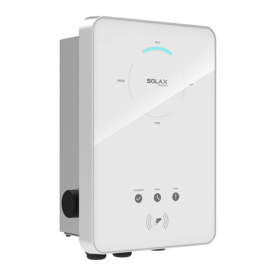
Page 6: Introduction
Introduction Introduction 3. Introduction 3.1 Basic Features 3.2 Structure of the EV-Charger Thanks for purchasing with the SolaX EV-Charger Series. The SolaX EV-Charger Dimension Ø Series can be used for charging your electric vehicle in your home. Also you can choose single or three phase with plug or socket type, you can consult our Type S salesmen for specific details. -
Page 7: General Data
Introduction Technical Data 4. Technical Data Type P 4.1 General Data Model X1-EVC-7.2K X3-EVC-11K X3-EVC-22K AC Nominal Input Phases/Lines 3 phase/L1+L2+L3+N+PE 3 phase/L1+L2+L3+N+PE single phase/L1+N+PE Voltage 230 V a.c. 400 V a.c. 400 V a.c. Frequency 50 Hz/60 Hz 50 Hz/60 Hz... -
Page 8: Security Protection
EV-Charger 7.2 kW-22 kW Copyright Declaration The copyright of this manual belongs to SolaX Power Network Technology (Zhejiang) Co., Ltd. Any corporation or individual should not plagiarize, partially or fully copy it (including software, etc.), and no reproduction or distribution of it in any form or by any means shall be allowed. -
Page 9: Installation Precaution
Installation Installation 5.3 Installation Precaution 5.4 Installation Steps Preparation The EV-charger is designed for wall-mounted installation (IP 65). Make sure the installation site meets the following conditions: ● Below tools are needed before installation. · Not exposed to sunlight directly. ·... - Page 10 Installation Installation STEP 2: Fix the back bracket and the cable hook (only for type P) to the wall. STEP 3: Hang the EV-Charger on the wall for trial, then estimate the required length of input cable and communication cable. After that, take the EV-Charger down. - Insert the expansion bolts.
- Page 11 Installation Installation STEP 5: Unscrew the countersunk screw of the base plate of communication board STEP 7: Strip the outer sheath of the input cable for a length of 70 mm, ensuring all the with the cross screwdriver. Then pull the base plate of communication board out . wires can reach the terminal blocks with a little excessive length.
- Page 12 Installation Installation STEP 9: Insert the wires into the terminal blocks, then block the terminal with the STEP 10: Press the spring upward and push the base plate of communication board in. traight screwdriver Then screw the countersunk screw. (torque:1~1.2 N·m) (torque:0.8~1.5 N·m)
- Page 13 Installation Installation Installation STEP 11: Push the rear cover to appropriate position of the cables and screw the For type P, connect the charging gun with the EV-Charger and hang the connecting self tapping screws with the cross screwdriver. Then tighten the waterproof cable on the hook.
-
Page 14: Ct Connection
Installation Installation Installation 5.5 CT connection -Steay the CT on the public grid. -Insert the other end of the communication cable and the terminal of CT on each Diagram: side of the adapter. grid EV-Charger PV array Three-phase Inverter AC breaker NOTE! •... -
Page 15: Run The Ev-Charger
Installation Operation Method 6. Operation Method 5.6 Run the EV-Charger Ø Start EV-Charger after checking all below steps: a) Check that the device is xed well on the wall. Control & Indicators b) Make sure all the AC breakers are turned off. c) AC cable is connected to grid correctly. -
Page 16: Status
Operation Method Operation Method Status GREEN Mode Six status can be set for the EV-Charger, i.e. Idle, Stop, Charging, Complete, Fault and Unavailable. In GREEN Mode the EV-Charger will maximize the use of surplus power generated from the inverter. According to the minimum start charging power, the charging current can be divided into two levels as 3 A and 6 A. -
Page 17: Eco Mode
Operation Method Operation Method ECO mode Smart Boost In ECO Mode, the charging power is continuously adjusted according to changes Before using the Smart Boost function, set the desired Charging Energy(kWh) and in generation or power consumption elsewhere in the house, thereby end time for the vehicle charging on the APP. - Page 18 Troubleshooting Troubleshooting 7 Troubleshooting 7.1 Troubleshooting 1.Unplug the connector from the EV; This section contains information and procedures for solving possible problems 2.If the "Fault" indicator is off, re-plug in and try charging with the EV-Charger, and provides you with troubleshooting tips to identify and EV again;...
-
Page 19: Routine Maintenance
Troubleshooting Troubleshooting 7.2 Routine Maintenance If your EV-Charger's information panel is not displaying a Fault light, check the ● The EV-Charger do not need any maintenance or correction in most condition. To following list to make sure that the present state of the installation allows proper ensure that the EV-Charger can operate properly for a long term, you are advised operation of the unit. -
Page 20: App Setting
Step 4: Type in or scan the Registration No. and type in other information to complete the registration. SINGLE-PHASE SMART EV CHARGER Model: X1-EVC-7.2K Nominal AC input/output voltage 230 V a.c. Nominal AC input/output current 32 A a.c. Nominal AC output power... - Page 21 App Setting App Setting Step 5: Wi-Fi setting successes. 2. Touch the “EV Charger” icon and then touch the setting button to enter the setting page. *Check more Wi-Fi setting information on www.solaxcloud.com/wi Setting/ Local Mode Use your smart phone to connect the SolaX Wi-Fi signal (Wi _SCxxxxxxxx). Then touch Local and type in password (initially same as the Registration No.) to access the Local Mode in the Monitoring App.
- Page 22 App Setting App Setting 6. Select “Advanced Settings” and a drop-down list will appear. 4. Select “Boost Settings” and a drop-down list will appear. Set the Start Time and 1)Set and save the value of “Overvoltage Limit”, “Undervoltage Limit”, “Overcurrent End Time for Timer Boost, the Charge energy and End Time for Smart Boost and the repeat frequency as you want.
-
Page 23: Decommissioning
Decommissioning Disclaimer 9 Decommissioning 10 Disclaimer The EV-Charger series are transported, used and operated under limited 9.1 Dismantling the EV-Charger condition, such as environmental, electrical etc. SolaX shall not be liable to provide the service, technical support or compensation under conditions Disconnect the EV-Charger from the inverter and the grid. - Page 24 Warranty Registration Form For Customer (Compulsory) Country Name Phone Number Email Address Zip Code State Product Serial Number Date of Commissioning Installation Company Name Installer Name Electrician License No. For Installer Module ( If Any ) Module Brand Module Size(W) Number of String Number of Panel Per String Battery ( If Any )
- Page 25 PLEASE REGISTER THE WARRANTY IMMEDIATELY AFTER INSTALLATION! GET YOUR WARRANTY CERTIFICATE FROM SOLAX! KEEP YOUR INVERTER ONLINE & WIN SOLAX POINTS! Open your Wait for the camera app camera to and point recognize your device the QR code at the QR code Notification Click the notification banner...
Need help?
Do you have a question about the X1-EVC-7.2K and is the answer not in the manual?
Questions and answers