Table of Contents
Advertisement
Quick Links
Installation, Operation, and Maintenance
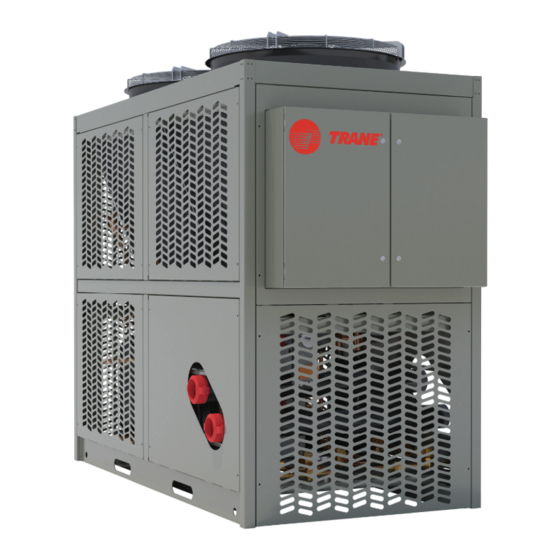
Thermafit™ Modular Air-to-Water
Heat Pump
Model AXM
Only qualified personnel should install and service the equipment. The installation, starting up, and servicing of heating, ventilating, and air-conditioning equipment
can be hazardous and requires specific knowledge and training. Improperly installed, adjusted or altered equipment by an unqualified person could result in death or
serious injury. When working on the equipment, observe all precautions in the literature and on the tags, stickers, and labels that are attached to the equipment.
February 2024
SAFETY WARNING
ARTC-SVX009A-EN
Advertisement
Table of Contents

Related Manuals for Trane Thermafit AXM


Summary of Contents for Trane Thermafit AXM
- Page 1 Installation, Operation, and Maintenance Thermafit™ Modular Air-to-Water Heat Pump Model AXM SAFETY WARNING Only qualified personnel should install and service the equipment. The installation, starting up, and servicing of heating, ventilating, and air-conditioning equipment can be hazardous and requires specific knowledge and training. Improperly installed, adjusted or altered equipment by an unqualified person could result in death or serious injury.
- Page 2 (HCFCs). Not all refrigerants containing these compounds bump cap, fall protection, electrical PPE and arc have the same potential impact to the environment. Trane flash clothing). ALWAYS refer to appropriate advocates the responsible handling of all refrigerants.
- Page 3 This document and the information in it are the property of regulations are more stringent than these Trane, and may not be used or reproduced in whole or in policies, those regulations supersede these part without written permission. Trane reserves the right to policies.
-
Page 4: Table Of Contents
Table of Contents Model Number and Coding ....6 Installation Piping......19 Heat Pump Model and Serial Numbers . - Page 5 Table of Contents Start-Up........52 Overview Circuits .
-
Page 6: Model Number And Coding
Refer to the Trane nameplate on each module in the installed unit for the serial number and model number. Table 1. Heat pump reference data... -
Page 7: Heat Pump Description
This manual provides relevant data to properly operate, construction and operation of the equipment. As required maintain, and troubleshoot the Trane AXM air-to-water under Federal regulations, installation, initial start-up, and modular heat pump. Operator and maintenance personnel... -
Page 8: Air Coils And Fans
Heat Pump Description Load Heat Exchanger Each module contains a BPHE, typically constructed with SAE Grade 316 stainless steel corrugated channel plates with copper filler material between each plate. The filler material forms a brazed joint at every contact point on the plates creating complex channels. This allows fluid to come into close proximity of the refrigerant, separated only by channel plates, thereby efficiently cooling or heating the fluid to the required temperature. -
Page 9: General Data
General Data Table 2. General data – Thermafit™ AXM air-to-water heat pump Capacity (Tons) General Unit Number of Independent Refrigeration Circuits DUAL R-454B Refrigerant Charge (lbs/module) Load Fluid Volume(gal/module) 18.44 Compressor Type VAPOR INJECTED SCROLL Quantity Load Heat Exchanger Type BRAZED PLATE Quantity Fluid Volume (gal) -
Page 10: Unit Dimensions And Weights
General Data Unit Dimensions and Weights Figure 1. AXM air-to-water heat pump 30 tons Table 3. Unit dimensions and weight - 30 tons (AXM) Unit Sizes and Weights Per Module Units inch Weight 3500 ARTC-SVX009A-EN... -
Page 11: Pre-Installation
A heat pump located away from such walls, fences, overhanging roof eaves, or is located in a pit obstacles operates more efficiently. (sub-level site), contact Trane to discuss potential impact on equipment performance. Minimum Clearances The National Electric Code or local, state, and regional... -
Page 12: Mounting Rails
Pre-Installation Figure 2. Recommended chiller clearances Note: These clearances are general recommendations. Each installation has specific considerations. Contact Trane for definitive guidance and approval on a job-by-job basis. Mounting Rails Figure 3. Heat pump installation on mounting rails The heat pump must be positioned on a firm, level surface. -
Page 13: A2L Work Procedures
At all times, Trane’s maintenance and service guidelines • Do not puncture refrigerant tubing. shall be followed. In in doubt, contact Trane technical support for assistance. • Dispose of properly in accordance with federal or local regulations. -
Page 14: Leak Detection
Use control settings, where available. When not available, manually open all electronically controlled valves using • Replace electrical components with Trane replacement acceptable service procedures. parts, or those meeting the same ratings and qualified for flame arrest protection, UL LZGH2 category. -
Page 15: Decommissioning
A2L Work Procedures • Cylinders shall be kept in an appropriate position a. Mechanical handling equipment is available, if according to the instructions. required, for handling refrigerant cylinders. • Ensure that the refrigerating system is earthed prior to b. All personal protective equipment is available charging the system with refrigerant. -
Page 16: Installation Mechanical
Any damage must be properly after installation. reported to the motor carrier and Trane within five days of The customer must notify Trane during the sales process receipt of the shipment. -
Page 17: Handling Of The Modules
Failure to adhere to these long-term storage requirements times. may void the Trane warranty. Any component that is • Remove all wire scraps, tools, replace all doors, damaged or inoperable due to improper storage may have covers and protective devices before powering its warranty voided. - Page 18 Installation Mechanical Figure 4. Recommended heat pump rigging ARTC-SVX009A-EN...
-
Page 19: Installation Piping
Installation Piping Install Piping and External each fluid system piping inlet for proper filtration an protection of the heat exchangers. Connect fluid piping with Components factory supplied roll grooved connections and insulate connections after assembly. The following figure provides a Proper support of piping and pipe hangers must consider recommended installation of components. -
Page 20: Drain Pans
Installation Piping Drain Pans The drain pan collects the water from the coil during defrost mode and diverts it to two drain tubes in each module. The drain tubes should be manifolded together by the customer and discharged to a local roof drain or other suitable drainage system to eliminate water and ice buildup near the unit. -
Page 21: Installation Electrical
Installation Electrical Connecting Module Power and individually on each module at the high voltage panel depending on option(s) selected. Connection entries Control Wires should be made in the lower left corner of the panel(s). See the following figure. Connections are typically made at the power distribution panel located on one end of the heat pump system or Figure 6. -
Page 22: Optional Disconnect Switch
Installation Electrical sets the under-voltage trip point. Check the phase monitor 2. Remove cable strain relief from back of cabinet, feed after initial start-up. If it fails to energize, (the LED glows cable end through strain relief. red or blinks) check the wiring of all three phases, voltage, 3. -
Page 23: Operating Principles
Operating Principles Minimum Fluid Volume and A typical HVAC system has a cooling requirement in the summer and shoulder seasons, and a heating requirement Avoidance of Short Loops in the winter and shoulder seasons. A modular air-to-water heat pump system provides an efficient means to address Adequate system fluid volume is an important system varying cooling and heating demands. -
Page 24: Operating Procedures
Operating Procedures Operator Interface Panel-Mounted Disconnect Switch Some heat pump systems are optionally equipped with a The modular heat pump systems, whether they are panel-mounted disconnect switch installed on the outside composed of two modules minimum or up to 10 modules, of the power distribution panel (or on each module’s are automated systems that use a main electrical panel to electrical and control panel if the heat pump has power... -
Page 25: Panel
Operating Procedures Module Electrical and Control Panel module has its own high voltage electrical panel and low voltage control panel that distributes electricity to individual The electrical and control panel receives power from the components. It also has fuses and breakers and power distribution panel and provides power to the microprocessor controller. -
Page 26: Operating The Microprocessor
(‘tech’) and administrator (‘admin’) levels that can only be This section consists of a tutorial that first-time personnel accessed by Trane technical personnel. Contact Trane can use to navigate through the various functions and technical support regarding the possibility of any potential features that are available in the interface. -
Page 27: Interface Menu Structure
Operating Procedures Interface Menu Structure Key interface screens are organized according to system, primary module, and secondary modules functions. See the following figure. Figure 12. Interface navigation scheme Home Screen Features Figure 13. HMI home screen ARTC-SVX009A-EN... - Page 28 Operating Procedures Table 4. Home screen features Feature Description 1 - HMI Software Version Calls up the pop-up window. See figure below. • Project Name: HMI software project name. • Software Version: HMI software version. • Consists of 4 two-digit numbers. –...
- Page 29 Operating Procedures Table 4. Home screen features (continued) Feature Description 5 - Setpoint Calls up cooling/heating setpoint pop-up screens respectively depending on the mode. Accessible for 'tech' only. These dialog boxes display the resulting cooling/heating setpoint used for machine temperature control. Note: The only box on these pop-ups accessible for 'tech' user.
- Page 30 Operating Procedures Table 4. Home screen features (continued) Feature Description 11 - System ON/OFF Button that calls up chiller on/off modes popup. The chiller on/off options are as follows: • OFF – turns off chiller bank. • ON – turns on chiller bank. •...
-
Page 31: Modules Layout Screen
Operating Procedures Modules Layout Screen Module Layout Screen Status Conditions Each module picture is a set of images that show real-time The heat pump can be composed of up to a maximum of color-coded state of compressor, refrigeration circuit, ten modules. Pressing the LAYOUT button displays the isolation valves, fans and module. -
Page 32: Active Alarms Screen
Operating Procedures Active Alarms Screen State Alarm is Active (Triggered) if State Value = 1 (still active in the PLC). Alarm is Not Active (Not Triggered), its State Value = 0 (can be reset using Reset button). Figure 18. Active alarms for the heat pump Both Active and Non Active alarms can be acknowledged. - Page 33 Operating Procedures Figure 19. Alarm history • Not Triggered – Alarm no longer appears (inactive), acknowledged, and reset (removed from Active Alarms list) State Alarm is Active (Triggered) if State Value = 1 (still active in the PLC) Alarm is Not Active (Not Triggered) if State Value = 0 (can be reset using Reset button) Both Active and Non Active alarms can be acknowledged.
-
Page 34: Module Access
Operating Procedures Module Access When Show Alarm Event is selected from the Status Filter drop-down list, any non-alarm events pertaining to user Buttons to access all heat pump modules screens action (acknowledgement and reset) is filtered off the list. individually. Number on the button “M(X)” stands for the Only alarm-related events appear. -
Page 35: Overview Module
Operating Procedures Table 6. The overview screens Primary Overview Module Screen Secondary Overview Module Screen Primary and Secondary Overview Circuit Screen Overview Module • OFF by switching Mode – Module is off and is going through a change of a major parameter. For instance, Module En/Dis Number of Refrigeration Circuits, Number of Fan Banks etc. -
Page 36: Overview Circuits
Operating Procedures – Primary module exists on the network, in other • Cool St Up/Dwn Dly – When next compressor has been words Primary PLC meets primary module staged up/down, this delay has to elapse before next conditions (see, “Primary Status,” p. 36). -
Page 37: Module I/O Screens
Operating Procedures • ON by Pumpdown – Compressor has been called off LEDs. Green – corresponding fan in the fan bank is but keeps running due to Pump-down sequence. (AC commanded on; Grey – corresponding fan is commanded Models Only). off. -
Page 38: Digital Leds
Operating Procedures When an I/O screen is displayed, switching to other I/O screens is accomplished by pressing their respective This output indicates Load Isolation Valve position. buttons: • The ANALOG button displays the analog screen. This output indicates the variable speed of Fan Bank 1. •... -
Page 39: Expansion Io Screen 1
Operating Procedures DO10 General Alarm – This output energizes when any of the This output indicates Liq Line Solenoid Circuit 2. It following alarms occur: energizes/deenergizes liquid line solenoid valve. • An alarm that shuts down and locks out compressor 1 or 2. -
Page 40: Setup Screen
Operating Procedures Figure 20. Module trend screen Table 8. Trend screen labels Label Description According to where the cursor is placed, it is capturing real time values of in and out water temperatures. Current cursor timestamps are displayed as well. Text box to select viewing time span. -
Page 41: Operator Tasks
Operating Procedures Figure 21. BMS communication Setup screen Feature Description BMS Online Status Indicates whether BMS is communicating to chiller bank or not. BMS Protocol Allows to select BMS communication type. The options are: • None – BMS communication disabled •... -
Page 42: Normal Power Up
Operating Procedures Emergency Power Shutdown Normal Power Up The following procedure is used for a start-up resulting The heat pump does not include a disconnect switch as from scheduled seasonal or programmed cold shut down of standard to turn off the high voltage to the modules. As per the heat pump. -
Page 43: Monitor Water Quality
3– of the heat pump. Chloride (Cl-) < 200 ppm Note: Trane will not validate the heat pump warranty if the Notes: proper water/glycol mixture composition and quality Total Hardness/corrosion: Water with high hardness can cause is not maintained. -
Page 44: Prevent Freezing
100 ppm. For best long-term results, de-ionized factors are the “best informed estimates” for heat pump or distilled water is recommended. Trane can provide with copper load heat exchangers. The percentages may concentrated solutions of Dowfrost, propylene glycol, or vary depending on the materials and alloys of the heat premixed solutions for use with the heat pump. - Page 45 Operating Procedures Figure 22. Water/Glycol concentration freezing points (in degrees fahrenheit) ARTC-SVX009A-EN...
-
Page 46: Controls Interface
Controls Interface Microprocessor Control System Figure 24. Touch interface panel AXM air-to-water modular heat pump models employ a Carel c.pCO all-digital data control system to control and report key system settings and indicators. Primary Microprocessor Controller Both the primary and secondary modules use a Carel c. pCO medium microprocessor controller. -
Page 47: Electrical Controls
Controls Interface Main Power Distribution Module Electrical and Control Panel The power distribution panel distributes electricity from the The Electrical and Control Panel receives power from the external building power supply. It also houses a circuit power distribution panel and provides power to the breaker for each module, a phase monitor, and an optional individual electrical components in that module. -
Page 48: Refrigeration Controls
Controls Interface NOTICE Superheat is factory-set for around 12°F (6.7°C). Close the valve to increase superheat. To accurately read superheat, Proof of Flow Switch! install a temperature sensor at the load heat exchanger Failure to provide flow switches or jumping-out of outlet. - Page 49 Controls Interface Sight Glass delay opens (times out) the normal controls are put back on line within the control circuit. When the sight glass shows a green indicator, no moisture is present. When the sight glass shows a yellow indicator, High and Low Ambient Controls there is moisture in the refrigerant line.
-
Page 50: Sequence Of Operations
Sequence of Operations This manual describes a typical air-to-water heat pump Rotation rotates Lead when the last compressor is system with few, if any, optional components or devices staged off. attached. 10. Primary Controller constantly monitors the Controlled Temperature and checks if it falls within Temperature Bank Controls Sequence Control Band. - Page 51 Sequence of Operations can be compensated by running additional modules in Heating Mode as driven by increased Heating Demand. ARTC-SVX009A-EN...
-
Page 52: Start-Up
Start-Up Preparation for Initial Start-Up off at the power distribution panel. Validate de- energization using voltage meter. After the system is completely installed with all wires 5. Inspect all electrical connections to confirm terminals connected and all piping securely coupled, the heat pump are secure. -
Page 53: Start-Up
Check the box if there are any customer-supplied devices connected to the heat pump wiring. ☐ List devices: ______________________________________________________________________________________ Check the box if there are any Trane remote devices connected to the heat pump wiring. ☐ Check the box if voltage drops are detected. -
Page 54: Maintenance Procedures
The primary goal of preventive maintenance is to avoid the lubrication fluids. consequences of equipment failure. Trane chillers are • Prudent maintenance strategy will anticipate and designed for ease of access with a premium placed on... -
Page 55: Weekly
Maintenance Procedures Table 13. Recommended heat pump service intervals Frequency Task Visually inspect the heat pump Daily Log pressure and temperatures Daily Inspect touchscreen interface panel for alarm history Weekly Clean strainers on the inlet water pipe Monthly Check the compressor oil level sight glass Monthly Confirm the glycol concentration Monthly... -
Page 56: Quarterly
Maintenance Procedures NOTICE Important: Extended operation with suction pressures below 80 psi is a clear sign of insufficient Equipment Damage! refrigerant charge, refrigeration obstruction, or Failure to remove moisture from system could cause valve closed. This can cause extensive corrosion within the chiller/heater components, and damage to a compressor. -
Page 57: Annually
Maintenance Procedures b. Verify refrigerant charge by recording the superheat WARNING and sub-cooling temperatures. Refrigerant under High Pressure! c. Observe head pressure for signs of improper Failure to follow instructions below could result in an condensing from clogged strainers, or a modulating explosion which could result in death or serious expansion valve issue. -
Page 58: Critical Cleaning Tasks
Replace the gasket and end cap and tighten coupling for heat exchanger cleaning. collar securely. On multiple module heat pumps, Trane provides service 9. Confirm the fluid make-up system is operational to isolation valves on each load heat exchanger to isolate... -
Page 59: Controller Tasks
Replace PLC Logic Controller a short period of time to loosen sediment and scale build-up. Trane recommends using straight tap water Prior to servicing the controller, verify that the power to the except in extreme cases. (Take extra precautions by heat pump is disconnected. -
Page 60: Heat Pump Troubleshooting
Isolation Fault detection is recognizing that a problem has occurred, Trane manufactures heat pump with embedded fault even if the root cause is not yet known. Fault isolation is the detection and diagnostics in each module’s controller that... - Page 61 Heat Pump Troubleshooting Table 14. Interface panel diagnostic code key (continued) Type Alarm Action Shuts down compressor 1 CoreSense 1 Failure User Reset CoreSense 1 Lockout User Reset Shuts down Circuit 1 Shuts down compressor 1 CoreSense 1 Offline Auto Reset Compressor 2 External Fault Shuts down compressor 2 Auto Reset...
- Page 62 Heat Pump Troubleshooting Table 14. Interface panel diagnostic code key (continued) Type Alarm Action Rosenberg Fan 1 Failure User Reset Shuts down Fan 1 Rosenberg Fan 1 Offline Auto Reset Shuts down Fan 1 Rosenberg Fan 2 Warning Warning Auto Reset Rosenberg Fan 2 Failure User Reset Shuts down Fan 2...
-
Page 63: Compressor Diagnostic Codes
Compressor Diagnostic Codes KRIWAN Flash Codes The KRIWAN flash code allows for a quick and easy status Compressors used in Trane air-to water heat pumps use display and troubleshooting. solid state protection and have PTC (Positive Temperature Coefficient) internal sensors with an avalanching The error code consists of a red and orange pulse resistance in the event of high temperatures. -
Page 64: Phase Monitor Protection
Heat Pump Troubleshooting Table 15. KRIWAN flash codes Error Category Flashing Sequence (red LED) Flashing Sequence (orange Error Status LED) Nominal response temperature of motor was exceeded Switch off due to blocked rotor Time delay active after motor Motor temperature temperature default Sensor fault motor PTC Time delay active after blocked rotor... - Page 65 Heat Pump Troubleshooting 1. Symptom: Compressor will not start Possible Causes Potential Solutions High pressure event has occurred; check fan settings and functionality; check High pressure switch open obstructed coils; check pressure switch functionality. Allow motor to cool and reset; High amp load/floodback; compressor Compressor overload opened operating outside of operating envelope.
- Page 66 Heat Pump Troubleshooting 5. Symptom: Compressor loses oil Possible Causes Potential Solutions Compressor short cycling Adjust proper control settings for Min. ON/OFF runtime. Check compressor superheat. Superheat at the compressor suction should be Liquid refrigerant approximately 12°F. 6. Symptom: Low refrigeration suction pressure Possible Causes Potential Solutions Lack of refrigerant...
- Page 67 Heat Pump Troubleshooting 8. Symptom: Low refrigerant discharge pressure Possible Causes Potential Solutions Low suction pressure See ‘Low refrigeration suction pressure’. Incorrect fan control settings Check fan settings. 9. Symptom: High refrigerant discharge pressure Possible Causes Potential Solutions System overcharged with refrigerant (especially at low ambient temperature in Remove excess refrigerant.
- Page 68 Heat Pump Troubleshooting 14. Symptom: Thermal Expansion valve superheat too high Possible Causes Potential Solutions Water/glycol temperature too warm Check setpoints; check charge. Obstructed filter dryer Replace dryer core. Low refrigerant charge Recharge refrigerant as per nameplate. Improper and not enough heat transfer at air coil Check tube and fin surface;...
-
Page 69: Request For Initial Startup
Trane at least 10 working days prior to the scheduled initial start-up As part of a continuous commitment to quality, initial start- up of this heat pump by a factory-certified technician may date. -
Page 70: Initial Start-Up Agreement
Request for Initial Startup Initial Start-Up Agreement start-up technician. Payment for an aborted start-up will be forfeited. Rescheduled initial start-ups are subject to any additional costs that may have been incurred by the technician. An approved purchase order or payment in By signing this form, you agree the heat pump is ready for advance will be required to reschedule an aborted initial initial start-up. - Page 71 Notes ARTC-SVX009A-EN...
- Page 72 For more information, please visit trane.com or tranetechnologies.com. Trane has a policy of continuous product and product data improvements and reserves the right to change design and specifications without notice. We are committed to using environmentally conscious print practices.
Need help?
Do you have a question about the Thermafit AXM and is the answer not in the manual?
Questions and answers