Advertisement
Quick Links
Owner's Manual
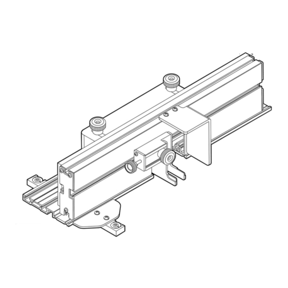
Box Joint Jig
Visit us on the web at www.powertecproducts.com
You will need this manual for safety instructions, operating procedures, and warranty.
Put it and the original sales invoice in a safe, dry place for future reference.
Model No. 71759
23-0604
Advertisement

Related Manuals for PowerTec 71759


Summary of Contents for PowerTec 71759
- Page 1 Model No. 71759 Owner's Manual Box Joint Jig Visit us on the web at www.powertecproducts.com You will need this manual for safety instructions, operating procedures, and warranty. Put it and the original sales invoice in a safe, dry place for future reference.
- Page 2 TABLE OF CONTENTS SAFETY RULES SECTION PAGE WARNING For your own safety, read all of the rules and precautions before operating tool. SAFETY RULES WARNING Safety Rules Always follow proper operating procedures as defined in this manual even if you are familiar with use of this Box Joint Jig or any tool used with this Box Joint Jig.
- Page 3 • A guard or any other part that is damaged should be properly SPECIFIC SAFETY RULES repaired or replaced. Do not perform makeshift repairs. • Use the right tool for your job. Do not force your tool to do a DANGER job for which it was not designed.
- Page 4 ASSEMBLY ASSEMBLY Assemble the Adjustment Mechanism: 1. See Figure 4-5. To assemble the Adjustment Mechanism (O) 1. See Figure 2. Attach Guide Plate ( I ) to Guide Bar (E) with take Adjustable Stop Plate (P) align with holes on the inset two Phillips Head Screws (H) of the Adjustment Mechanism and secure with two Phillips 2.
- Page 5 NOTE: If you do not have a table saw and dado blade set this next cutting position. POWERTEC Box Joint Jig can also be used on a router table. 7. Lift the boards in and out checking for ease of movement while positioning in place.
- Page 6 Set the Spacing for Box Joints: Cut the Test Joint: Please note it will be necessary to remove Clamp Guard (L) to set 1. If needed, move MDF Sub Fence (C) to a fresh section. the Stop Plates. Replace, using the steps shown in Figure 10 This will provide support and help prevent the pins from before making cuts.
- Page 7 If Adjustment is needed: Cut Remaining Joints: This step will help produce consistent, equal spacing to the 1. See Figure 19. To setup the adjoining workpiece, reverse remaining cuts. the first "A-B" workpiece 180° (flip horizontally) to follow configuration for assembly. The face of the A-B board will 1.
- Page 8 30 - DAY SATISFACTION GUARANTEE POLICY During the first 30 days after the date of purchase, if you are dissatisfied with the performance of this POWERTEC tool for any reason, you may return the tool to the retailer from which it was purchased for a full refund or exchange. You must present proof of purchase and return all original equipment packaged with the original product.
Need help?
Do you have a question about the 71759 and is the answer not in the manual?
Questions and answers