Table of Contents
Advertisement
Quick Links
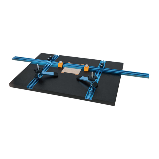
INSTRUCTION SHEET
71184 Drill Press Table 16" x 24" with
QUESTION...
1•847•780•6120
WARNING
This product is to be used with a drill press. Before using this
product, always read, understand and follow the instructions
and safety warnings in the owner's manual for the drill press. If
you do not have the owner's manual, obtain one from the tool's
manufacturer before using it with this product.
You must be familiar with the use of any tool or accessory used
with this drill press table/fence system. The supplier cannot be
held responsible for any accident, injury or damage incurred
while using this drill press table/fence system with any tool.
It is the responsibility of the purchaser of this product to ensure
that any person using this product reads and complies with all
instructions and safety precautions outlined in this manual and
the operating manual of the tool being used prior to use.
CAUTION
Do not modify or use this drill press table/fence system for any
application other than that for which it was designed.
WARNING
• To avoid serious injury, turn off and unplug the drill press
before attaching, adjusting or changing accessories.
CAUTION
Think safety! Safety is a combination of operator common sense
and alertness at all times when tool is being used.
WARNING
Do not use the drill press table/fence system until it is completely
assembled and you have read and understood this entire
operating manual and the operating manual of the tool being
used with this drill press table/fence system.
SAVE ALL WARNINGS AND INSTRUCTIONS
FOR FUTURE REFERENCE
PACKAGING CONTENTS
ITEM
DESCRIPTION
A
16" x 24" Table with mounted double wide
engraved T-Tracks
B
36" Double Wide Engraved Fence
ITEM
DESCRIPTION
C
D
1/4"-20 x 1" T-Bolts
E
1/4"-20 x 5/8" Round Knobs (metal)
F
5-1/2" Hold Down Clamps
G
5/16"-18 x 3-1/2" T-Bolts
H
5/16" Washers
I
5/16"-18 Five Star Knobs
J
Fence Mounting Blocks
K
1/4"-20 x 1-1/2" T-Bolts
L
1/4"-20 x 3/4" Round Knobs (plastic)
M
N
#6 x 1/2" Adjustment Screws (Insert)
O
1" Fender Washers
P
#10 x 1-1/4" Pan Head Screws
Q
5/16"-18 x 1" Hex Bolts
R
Oval Nuts
Figure 1
A
B
F
H
G
ASSEMBLY
Assemble to Drill Press
Refer to Figure 2–5
Installation to Through Slotted Drill Press Tables
1.
Place the POWERTEC table onto the drill press table with
the short side of insert opening to the column as shown.
2.
Insert a 3/8" bit into the drill chuck and feed it through the
calibration hole in the table insert. Square the table and lock
the spindle.
Figure 2
QTY
Calibration Hole
1
1
M
Q
H
R
J
K D
L
C
D E
I
Table Insert
QTY
2
4
2
2
2
6
2
2
2
4
1
4
4
4
4
4
N
P
O
Column
Table
21-0514
Advertisement
Table of Contents

Related Manuals for PowerTec 71184


Summary of Contents for PowerTec 71184
- Page 1 Think safety! Safety is a combination of operator common sense Installation to Through Slotted Drill Press Tables and alertness at all times when tool is being used. Place the POWERTEC table onto the drill press table with WARNING the short side of insert opening to the column as shown.
- Page 2 Making sure the POWERTEC table is centered on the adapter board, pre-drill two 5/32" holes into the The marked location on the bottom of the POWERTEC table bottom of the table. DO NOT drill through the table. Place the POWERTEC table back onto the drill press table, Use four #10 x 1-1/4"...
- Page 3 Place the insert into the opening and check with a straight Slide the fence horizontally across the table to the desired edge. Use a Phillips screw driver to adjust the screws until position. Tighten the front knobs on the fence mounting the insert is flush with the top of the table.
- Page 4 To Adjust the Flip Stop Figure 14 • Flip up the flip stop. • Slide the flip stop along the fence to the desired position. • Flip the stop down to lock into position on the fence. Figure 12 Flipped UP Flipped DOWN Figure 15 Hold Down Clamps...
Need help?
Do you have a question about the 71184 and is the answer not in the manual?
Questions and answers