Table of Contents
Advertisement
Quick Links
Advertisement
Table of Contents

Related Manuals for PowerTec DP801


Summary of Contents for PowerTec DP801
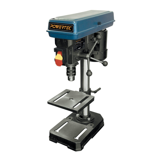
- Page 1 Model No. DP801 Owner’s Manual 8” DRILL PRESS QUESTION... 1•877•393•7121 Visit us on the web at www.southerntechllc.com You will need this manual for safety instructions, operating procedures, and warranty. Put it and the original sales invoice in a safe, dry place for future reference.
-
Page 2: Table Of Contents
TABLE OF CONTENTS PRODUCTION SPECIFICATIONS SECTION PAGE SAFETY RULES Peak HP................2/5 5 Speeds ......620, 1100, 1720, 2340, 3100 RPM Work Preparation Swing ................8" Work Area Preparation Tool Maintenance Chuck ................1/2" Tool Operation Spindle Travel..............2" Table Size ............6-1/2" x 6-1/2" ASSEMBLY Table Movement......45°... -
Page 3: Safety Rules
SAFETY RULES TOOL MAINTENANCE WARNING • Turn the machine "OFF", and disconnect the machine For your own safety, read and understand all warnings from the power source prior to inspection. and operating instructions before using any tool or • Maintain all tools and machines in peak condition. Keep equipment. -
Page 4: Assembly
ASSEMBLY UNPACKAGING Refer to Figure 1. • Check freight damage before opening the package. If freight damage is noticed, file claim with the carrier immediately. • Check for complete part list. Contact Customer Service Center immediately for missing parts. • Locate the following parts before assembling: A. -
Page 5: Install Column Support
INSTALL THE DRILL PRESS HEAD WARNING Refer to Figure 4 The drill press is designed to be safely assembled by at least two people working together. • Position and slide the head over the column. • Carefully rotate the head on the column so it is aligned INSTALL COLUMN SUPPORT with the base. -
Page 6: Install Chuck
INSTALL THE CHUCK POWER SOURCE Refer to Figure 6 WARNING Do not connect to the power source until the machine is WARNING completely assembled. Clean the spindle taper and the tapered hole in the chuck The machine is wired for 120 volts, 60 Hz alternating before assembly. -
Page 7: Extension Cords
In Canada, the use of temporary adapter is not permitted WARNING by the Canadian Electric Code. Where permitted, the rigid Do not permit fingers to touch the terminals of plug when green tab or terminal on the side of the adapter must be installing or removing from outlet. -
Page 8: Operation
OPERATION DESCRIPTION Figure 10 - On-Off Switch Powertec 8” drill press equipped with 5 speeds ranging from 620 RPM, 1100RPM, 1720RPM, 2340RPM and 3100RPM. WARNING For your own safety, read the entire operation manual and safety instructions before using the machine. -
Page 9: Adjust Depth Stop
ADJUST SPEEDS Figure 14 Refer to Figure 13 WARNING Turn the switch to “OFF” position and disconnect the machine from power source. Chuck Key This drill press has 5 speeds: 620 RPM, 1000RPM, 1720RPM, 2340RPM and 3100RPM. The Chuck Jaws speed is determined by the location of the belt on the pulleys. -
Page 10: Adjust Belt Tension
ADJUST BELT TENSION Figure 16 Refer to Figure 16 Belt Tension The drill spindle speed is determined by the position of the Lock Knob belts on the pulleys inside the head assembly. • To unlock the belt tension, turn the belt tension lock knob on the right side of the drill press head counterclockwise. -
Page 11: Troubleshooting
TROUBLESHOOTING SYMPTON POSSIBLE CAUSE(S) SOLUTIONS Motor will not start 1. Low voltage 1. Check power supply for proper voltage 2. Short circuit in line cord or plug 2. Inspect line cord and plug for faulty insulation or shorted connection 3. Short circuit in motor 3. -
Page 12: Parts Illustration
8” DRILL PRESS PARTS ILLUSTRATION... - Page 13 8” DRILL PRESS PARTS LIST Key No. Part No. Part Name Key No. Part No. Part Name DP801001 KNOB DP801044 NUT M8 DP801002 NUT M5 DP801045 BOLT DP801003 WIRE PRESS BUCKLE DP801046 HEAD BODY DP801004 PAN HEAD SCREW M6*8 DP801047 ANGLE SCALE DP801005 PULLEY HOUSING...
-
Page 14: Warranty
30- DAY SATISFACTION GUARANTEE POLICY During the first 30 days after the date of purchase, if you are dissatisfied with the performance of this POWERTEC tool for any reason you may return the tool to the retailer from which it was purchased for a full refund or exchange. You must present proof of purchase and return all original equipment packaged with the original product. - Page 15 DISCLAIMER To the extent permitted by applicable law, all implied warranties, including warranties of MERCHANTABILITY or FITNESS FOR A PARTICULAR PURPOSE, are disclaimed. Any implied warranties, that cannot be disclaimed under state law are limited to one year from the date of purchase. Southern Technologies LLC. is not responsible for direct, indirect, incidental or consequential damages.
- Page 16 Southern Technologies, LLC 206 Terrace Drive Mundelein, Illinois 60060...
Need help?
Do you have a question about the DP801 and is the answer not in the manual?
Questions and answers