
Related Manuals for Yamaha FS1R


Summary of Contents for Yamaha FS1R
- Page 1 OWNER’S MANUAL...
-
Page 2: Special Message Section
SPECIFICATIONS SUBJECT TO CHANGE: The information contained in this manual is believed to be correct at the time of printing. However, Yamaha reserves the right to change or modify any of the specifications without notice or obligation to update existing units. -
Page 3: Important Safety Instructions
Please make sure that benches are stable and any optional fixtures (where applicable) are well secured BEFORE using. Benches supplied by Yamaha are designed for seating only. No other uses are recommended. - Page 4 Compliance with FCC regulations does not guarantee that interference will not * This applies only to products distributed by YAMAHA CORPORATION OF AMERICA. ADVARSEL! Lithiumbatteri—Eksplosionsfare ved fejlagtig håndtering. Udskiftning må...
- Page 5 If this should happen, consult a physician immediately. SAVING USER DATA • Save all data to an external device such as the Yamaha MIDI Data Filer MDF3, in order to help prevent the loss of important data due to a malfunction or user operating error.
- Page 6 Congratulations! Your FS1R Format Shaping/FM Synthesis Tone Generator gives you the power of two extraordinary tone generation systems in one compact, easy-to-use rack-mount unit. Formant Shaping synthesis gives musicians unprecedented capability to produce and control sounds with characteristics and flexibility similar to that of the human voice. It can also produce instrument voices that have the response and rich pitch-dependent timbral variations.
-
Page 7: Table Of Contents
FS (Formant Shaping) and FM (Frequency Modulation) Synthesis ...8 FS Synthesis ...8 *Formant Control...9 *Formant Sequences:“FSeqs” ...10 *Other Formant Applications ...11 FM Synthesis...11 *FM In Brief ...12 Putting It All Together...13 The Controls & Connectors ...14 Front Panel ...14 Rear Panel ...16 Setting Up ...17 Power Supply ...17 MIDI Connections ...17... -
Page 8: Fs (Formant Shaping) And Fm (Frequency Modulation) Synthesis
(e.g. to produce percussive sounds or sound effects). The term “operators” is borrowed from Yamaha FM synthesis, because the FS1R’s voiced operators can be combined in a variety of “algorithms” to create sound in exactly the same way as in the original FM synthesizers such as the DX7. -
Page 9: Formant Control
Either of these methods of formant control are all you’ll need to create musical sounds for most applications, but the last and most complex type of formant control on the FS1R is made possible by “FSeqs” (Formant Sequences), described in the following section. -
Page 10: Formant Sequences:"Fseqs
• EDIT [VOICE] mode OPERATOR/Sns/FreqVelocity...Page 68 Formant Sequences: “FSeqs” In addition to envelope generator, LFO1, velocity, and manual control, the FS1R features a range of 90 preset FSeqs (Formant Sequences) which can be used to “sequence” the formants to produce voice-like phrases, rhythm loops, and more. -
Page 11: Other Formant Applications
The FS1R actually takes FM synthesis to new levels of musical versatility and control. Unlike Yamaha’s original FM synthesizers and tone generators the FS1R provides a range of 88 algorithms to choose from, and a choice of 8 different waveforms for each oscillator, thus significantly expanding the range of sound which can be produced. -
Page 12: Fm In Brief
— in “algorithms” capable of producing the desired sound. the most simple algorithm (algorithm 1 in the FS1R) simply add the output of all 8 operators together, with no modulator-carrier relationships. This algorithm is ideal for synthesizing simple “additive” sounds — like some organ voices, for example. -
Page 13: Putting It All Together
Indeed, the FS1R is a complex tone generator, and a thorough understanding can only be achieved through experimentation. If you want to go beyond the presets provided (although they should be more than enough for many applications), we urge you to go ahead and play with the parameters. -
Page 14: The Controls & Connectors
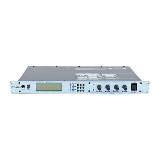
The Controls & Connectors The following brief descriptions of the FS1R controls and connectors should help you to understand the overall logic of the interface. Front Panel 1 PHONES Jack Accepts a standard pair of stereo headphones (1/4” stereo phone plug) for headphone monitoring of the FS1R sound without the need for external amplification equipment. -
Page 15: Knob Mode Buttons
) Controller Knobs These four multi-function controller knobs make realtime sound control and editing on the FS1R easier than ever. In the PLAY mode they allow direct realtime control of the sound as well as parameter editing, and in the EDIT mode they can be used to directly change parameters and values for fast, efficient operation. -
Page 16: Rear Panel
MIDI IN connector, allowing convenient chaining of MIDI devices. The MIDI OUT connector transmits data corresponding to FS1R controller knob operation, or bulk data when one of the MIDI data transmission functions are activated. Details on page 17. -
Page 17: Setting Up
WARNING! • Make sure your FS1R is rated for the AC voltage supplied in the area in which it is to be used (as listed on the rear panel). Connecting the unit to the wrong AC supply can cause serious damage to the internal circuitry and may even pose a shock hazard! •... -
Page 18: Sequencer Or Computer
Since the G50 produces MIDI output, the standard MIDI connection rules that apply to a keyboard or any other MIDI controller also apply when connecting the G50 to the FS1R. One feature of the FS1R which makes it ideal for use with the G50 is the ability to allow reception on a specified range of MIDI channels for each performance part. -
Page 19: Audio Connections
WX Lip Sensor and Pitch Bend data as transmitted in the form of MIDI pitch bend data. Be sure to set an appropriate pitch bend range on your FS1R. For subtle control a pitch bend range setting of between about 2 and 4 should be ideal. -
Page 20: Power-On Procedure
Some keyboards and other MIDI controllers automatically transmit MIDI control change data corresponding to their control status when the power switch is turned ON or OFF. The FS1R is programmed to receive this data and respond accordingly, so it is preferable to turn the FS1R ON before turning the controlling device ON. -
Page 21: The Play Mode
The PLAY mode is initially selected when the FS1R power is turned on, and can be selected from any other mode by pressing the [PLAY] button. This mode allows performance setups and voices to be selected and played, and thus is the mode you’ll normally use when playing the FS1R. -
Page 22: Bank Selection Via Midi
The Play Mode (Performance) This is the mode you will normally use when playing the FS1R, and is initially selected when the FS1R power is turned on. If the PART ASSIGN mode is active (see page 24), the PERFORMANCE mode can be selected by... -
Page 23: Perf Ch (Performance Channel)
When the UTILITY mode SYSTEM/MIDI/PgmMode parameter is set to “multi” (e.g. when playing the FS1R from a sequencer or computer), the FS1R functions as a multi-timbre tone generator, allowing the parts to be individually controlled via their respective MIDI channels. If the PLAY mode Pfm Ch parameter is set to any value other than “off”, however, all bank select, program change, volume, and pan data... -
Page 24: Varrtn (Variation Return)
VarRtn (Variation Return) Settings: 000 … 127 Adjusts the level of the signal returned from the FS1R variation effect stage. The higher the value, the higher the level of the variation signal. PfmNSft (Performance Note Shift) Settings: -24 … 0 … +24 Transposes the pitch of the performance setup down or up in semitone steps over a ±2 octave range. -
Page 25: Rcv Ch (Receive Channel)
In either case the part to be edited - 01 through 04 - can be selected via the PART [ selected part number appears above “PART” in the lower left corner of the display). The various parameters are selected via the CURSOR [ ] and [ upper right corner of the display, and the solid triangular pointer indicates which of the parameters is selected. -
Page 26: Revsend (Reverb Send)
RevSend (Reverb Send) Settings: 000 … 127 Adjusts the level of the signal sent to the FS1R reverb effect stage. The higher the value, the higher the level of the reverb send signal. VarSend (Variation Send) Settings: 000 … 127 Adjusts the level of the signal sent to the FS1R variation effect stage. -
Page 27: The Search Function
The Search Function The FS1R Search function makes it easy to find a specific voice or performance from within the large number of presets provided. The Search function can also be used to locate original performance setups or voices you have created yourself and assigned to a category via the EDIT [PERFORMANCE] or EDIT [VOICE] mode “Catgry”... -
Page 28: Editing
The EDIT [PERFORMANCE], [EFFECT], or [VOICE] mode can be accessed from the PLAY mode as follows: Select an Edit Mode Press the EDIT button corresponding to the type of parameters you want to edit: [PERFORMANCE], [EFFECT], or [VOICE]. See the FS1R Parameter Groups chart, below. Select a Parameter Group Use the CURSOR [... -
Page 29: The [Mute/Solo] Button In The Edit Modes
Select a Parameter Use the CURSOR [ ] and [ the parameter you want to edit. The parameter number appears in the top right corner of the display. The name of the currently selected parameter and its current setting appear on the second line of the display. An arrow to the left and/or right of the parameter name/value indicates that the CURSOR [ 3 (when both Knob Mode buttons are disengaged) can be used to select more parameters in the indicated direction. -
Page 30: Edit [Performance]
CtrlSrc (Control Source) One of the most powerful features of the FS1R controller system is the ability to create “voice control sets” for realtime performance control. Up to 8 voice control sets - “VC1” through “VC8” - can be created for each performance setup. -
Page 31: Ctrldst (Control Destination)
In the CtrlSrc parameter group you can turn any of the available source controllers on or off for any of the 8 voice control sets: “VC1” through “VC8.” The CURSOR [ and controller combinations. For example, when “VC1 by KN3” is “on”, Knob 3 is assigned to control whichever destination parameter and parts and assigned to voice control set 1 (“VC1”) via the CtrlDst parameters, below. -
Page 32: Fseq (Format Sequence)
Specifies the Fseq to be assigned to the part selected in the Part parameter, above. 90 Preset formant sequences are available. An addition 6 internal formant sequences, transferred to the FS1R from an external device via MIDI, can be made available if the UTILITY mode SYSTEM/Others/Mem parameter is set to “IntVoice 64” (page 76). - Page 33 Use the CURSOR [ ] and[ ] buttons to select the bank (Pre/Int) or number parameter, and the VALUE [ ] buttons to set as required. “Pre” (Preset) or “Int” (Internal) can be selected when the left triangular pointer is highlighted, and the Fseq number can be selected when the right triangular pointer is highlighted. Please note that only the Fseq pitch data will be effective if the EDIT [VOICE] mode OPERATOR/Osc/FseqSw parameter is turned off for all operators.
- Page 34 • 08: Pitch Pitch Mode Settings: fseq, fixed Determines whether or not the pitch data included in the formant sequence data will be used for Fseq playback. Setting fseq The Fseq pitch data is used for Fseq playback. fixed The Fseq pitch data is not used for Fseq playback. •...
-
Page 35: Others
This parameter, in conjunction with the insEfSw parameters for each part (page 26), determines how the individual parts are assigned to the FS1R’s INDIVIDUAL OUTPUT jacks. When “off” no signal is delivered via the individual outputs. When set to “pre ins” only parts for which the InsEfSw parameter is turned “on” will appear at the individual outputs, and the sound will be “dry”... - Page 36 Settings: —, Pf, Cp, Or, Gt, Ba, St, En, Br, Rd, Pi, Ld, Pd, Fx, Et, Pc, Se, Dr, Sc, Vo, Co, Wv, Sq Specifies the Category assignment for the current performance setup. The category assignments are used by the FS1R SEARCH function (page 26). The meanings of the settings are listed below. • 03: Name Performance Name Settings: A performance name of up to 12 characters.
-
Page 37: Part
PART In any of the PART EDIT modes the PART [ selected part number appears in the lower left corner of the display, and the bar corresponding to the selected part will flash in the upper right corner of the display, to the left of the parameter number. Parameter Group •... - Page 38 • 03: V/N Balance Voiced/Unvoiced Balance Settings: -64 … +63 Specifies the balance between the voiced and unvoiced (noise) operators. A setting of “+0” produces equal balance between the voiced and unvoiced operators. Positive values increase the level of the unvoiced operators in relation to the voiced operators, and negative values increase the level of the voiced operators in relation to the unvoiced operators.
-
Page 39: Eg (Envelope Generator)
• 10: Flt EGDepth (only available when Filter Sw “on”) Filter EG Depth -64 … +63 The “FiltEGDept” parameter determines to what degree the envelope generator (page 56) affects the filter’s cutoff frequency. Higher values allow the envelope generator to vary the filter cutoff frequency over a wider range. This parameter offsets the value of the EDIT [VOICE] mode COMMON/Filter/EG Depth parameter. -
Page 40: Pitch
The “Detune” parameter allows the pitch of the selected part to be shifted slightly upward or downward to produce detune effects in relation to other parts or other tone generators being used with the FS1R. Positive values shift the pitch upward, and negative values shift the pitch downward. -
Page 41: Others
“127” produces the longest portamento slide effect. Others • 01: Mono/Poly Monophonic/Polyphonic Mode Settings: mono, poly Selects the FS1R monophonic or polyphonic note mode. When “mono” is selected the note priority is determined by the setting of the Priority parameter, below. - Page 42 Low Velocity Limit Settings: 1 … 127 Specifies the lowest velocity value which will be recognized by the FS1R. This and the Vel LimitH parameter, below, specify the FS1R velocity range. If the VelLimitL parameter is set to a velocity value which is higher than that specified by the VelLimitH parameter, below, no sound will be produced between the VelLimitL and VelLimitH velocities.
- Page 43 Settings: 0 … 127 Specifies the lowest MIDI expression control change message which will be recognized by the FS1R, and therefore the lowest volume level which will be produce when, for example, an expression pedal is rocked all the way backward.
-
Page 44: Store Performance
Press the [ENTER] button again to actually store the performance setup, or [EXIT] to cancel. “Executing” will appear on the display briefly while the data is being stored, then the FS1R will return to the EDIT [PERFORMANCE] mode menu. -
Page 45: Edit [Effect]
Effect Signal Flow Refer to the diagram on page 13 for an overview of how the FS1R effect stages relate to overall signal flow. Note that the Reverb and Variation stages are overall effects, in which the amount of signal sent to the effect from each of the FS1R’S parts is individually controlled by the part RevSend and VarSend parameters (page 26). -
Page 46: Type
This parameter duplicates the PLAY mode Rev Rtn parameter (page 23), adjusting the level of the signal returned from the FS1R reverb effect stage. The higher the value, the higher the level of the reverb signal. The Variation stage includes reverb, delay, echo, modulation, distortion, wah, and a range of other effects. -
Page 47: Var Pan
Settings: 0 … 127 This parameter duplicates the PLAY mode Var Rtn parameter (page 24), adjusting the level of the signal returned from the FS1R Variation effect stage. The higher the value, the higher the level of the variation signal. SendVar Rev Variation-to-Reverb Send Level Settings: 0 …... -
Page 48: Sendins Rev
SendIns Rev Insertion-to-Reverb Send Level Settings: 0 … 127 Sets the amount of signal sent from the output of the insertion effect stage back to the input of the reverb effect stage (see diagram on page 13). The higher the value, the more insertion signal is sent to the reverb stage. SendIns Var Insertion-to-Variation Send Level Settings: 0 …... -
Page 49: Mid Freq
Mid Freq Mid-band Frequency Settings: 100 … 10.0k Sets the center frequency of the middle EQ band. Mid Gain Mid-band Gain Settings: -12 … 0 … +12 Sets the amount of boost (“+” settings) or cut (“-” settings) applied to the middle EQ band. Mid Q Low-band Q Settings: 0.1 …... -
Page 50: Edit [Voice]
EDIT [VOICE] The EDIT [VOICE] mode provides access to the FS1R’s in-depth voice editing parameters. COMMON Second Group • LFO1 • LFO2 • Filter • PitchEG • Others Parameter Waveform Speed Delay Key Sync Pitch Modulation Depth Amplitude Modulation Depth... -
Page 51: Lfo1 (Low Frequency Oscillator 1)
LFO1 (Low Frequency Oscillator 1) • 01: Waveform Waveform Settings: tri, s-dn, s-up, squ, sine, s/h Determines the waveform of the LFO. tri (Triangle) s-dwn (Downward sawtooth) s-up (Upward sawtooth) squ (Square) sine (Sine) • 02: Speed Speed Settings: 0 … 99 Sets the speed of the LFO. -
Page 52: Lfo2 (Low Frequency Oscillator 2)
• 06: AmpMod Depth Amplitude Modulation Depth Settings: 0 … 99 Sets the maximum amount of amplitude modulation that can be applied to the current voice. A “0” setting produces no modulation while a setting of “99” produces maximum modulation. Amplitude modulation produces a periodic variation in the volume of the sound, thus creating a tremolo effect. -
Page 53: Filter
• 03: Key Sync Key Synchronization Settings: off, on Determined whether the LFO runs continuously (off), or is triggered by notes played (on) so that modulation always begins from the same point in the LFO waveform when a note is played. •... - Page 54 • 03: Type Filter Type Settings: LPF24, LPF18, LPF12, HPF, BPF, BEF Determines the type of filter response used. The “LPF” (Low Pass Filter) settings produces a filter response that allows only frequencies below the cutoff frequency (See “Cutoff Freq” below) to pass. The “LPF24” filter type has a steep -24dB/octave cutoff slope, the “LPF18”...
- Page 55 The FreqScaling and F.Scale BP parameters work together to produce a variation in filter cutoff frequency across the range of the keyboard or other MIDI controller used with the FS1R. When a positive FreqScaling value is specified (“+1” … “+63”) the filter cutoff frequency increases to the right of the breakpoint specified by the F.Scale BP parameter, and decreases to the left of the breakpoint.
- Page 56 Settings: -50 … +50 The FS1R filter envelope generator has four individually programmable time and level parameters which function in much the same way as they do in the amplitude envelope generator (page 66), except that they control filter cutoff frequency rather than operator amplitude.
-
Page 57: Pitcheg (Pitch Envelope Generator)
Settings: -50 … +50 The FS1R pitch envelope generator has four individually programmable time and level parameters which function in much the same way as they do in the amplitude envelope generator (page 66), except that they control pitch rather than operator amplitude. -
Page 58: Others
Key On Higher Time parameter values produce correspondingly longer times. A time setting of “0” will result in an almost instantaneous transition between the related levels, while a setting of “99” will produce the longest transition between the related levels. The level parameters are actually “offset”... - Page 59 • 02: Feedback Feedback Settings: 0 … 7 Sets the amount of feedback applied to the feedback operator in the currently selected algorithm. Higher values apply a greater amount of feedback. The operator to which feedback can be applied in the selected algorithm is indicated at the bottom of the display by “FBOP”...
- Page 60 Settings: —, Pf, Cp, Or, Gt, Ba, St, En, Br, Rd, Pi, Ld, Pd, Fx, Et, Pc, Se, Dr, Sc, Vo, Co, Wv, Sq Specifies the Category assignment for the current voice. The category assignments are used by the FS1R SEARCH function (page 27).
-
Page 61: Operator
OPERATOR In any of the OPERATOR edit displays the PART [ Knob Mode buttons are disengaged) can be used to select the operator to be edited: Voiced operators 1 through 8 (V:OP1 through V:OP8) and unvoiced operators 1 through 8 (N:OP1 through N:OP8). The selected operator number appears in the upper left corner of the display, and the level bar corresponding to the selected operator will flash in the upper right corner of the display, to the left of the parameter number. -
Page 62: Osc (Oscillator)
Osc (Oscillator) • 01 (N:01): Fseq Switch (V & N) Fseq Switch Settings: off, on Turns Fseq playback on or off. When on, the Fseq selected via the EDIT [PERFORMANCE] mode COMMON/Fseq/Fseq parameter will play. Please note that the Fseq pitch data will play even if this parameter is set to “off”. - Page 63 • 04 (N:02): FreqMode (V & N) Frequency Mode Settings: (Voiced) ratio, fixed (Unvoiced) normal, linkFO, linkFF Specifies the frequency mode for the currently selected operator. For voiced operators, the “fixed” setting causes the operator to remain at a fixed frequency regardless of the note played.
- Page 64 • 08 (N:06): Transpose (V & N) Transpose Settings: -24 … +24 This parameter is only effective when the “frmnt” spectral form (see “Form” parameter, above) is selected. Transposes the center frequency of the operator’s formant up or down by up to two octaves in semitone steps. Each increment transposes the frequency up (“+”...
- Page 65 • 14: LS LeftDepth (V) Level Scaling Left Depth Settings: 0 … 99 • 15: LS LeftCrv (V) Level Scaling Left Curve Settings: -lin, -exp, +lin, +exp • 16: LS BP (V) Level Scaling Breakpoint Settings: A-1 … C8 • 17: LS RightDepth (V) Level Scaling Right Depth Settings: 0 …...
-
Page 66: Eg (Amplitude Envelope Generator)
• 19: LevelScaling (N) Level Scaling Settings: -7 … +7 This parameter works only with unvoiced operators, making it possible to produce natural noise-level variations across the range of the keyboard or other controller. When a positive LevelScaling value is specified the operator level increases to the right of C3, and decreases to the left of C3. -
Page 67: Frqeg (Frequency Eg)
Level 1 … Level 4 Settings: 0 … 99 The FS1R amplitude envelope generator has four individually programmable time and level parameters for exceptional envelope programming flexibility. Next to the actual waveform of the sound, the amplitude envelope is one of the most important factors determining the overall sound of a voice. -
Page 68: Sns (Sensitivity)
• 04: Decay Time (V & N) Decay Time Settings: 0 … 99 These four parameters determine the shape of the frequency envelope generator for the selected operator. The envelope starts at the initial level (“InitLevel”) at key-on, and then approaches the attack level (“AttackLevel”) at a speed determined by the “Attack Time”... - Page 69 • 03: Amp EG Bias (V & N) Amplitude EG Bias Settings: -7 … +7 This parameter becomes effective when “Amp EG Bias” is assigned as a control destination (page 31), and sets the depth and type of response of amplitude EG bias. EG bias increases or decreases the amplitude envelope generator levels, simulating the dynamic variations that can be produced on an acoustic instrument more accurately than simple volume control.
-
Page 70: Store Voice
Press the [ENTER] button to recall the edited data, or [EXIT] to cancel. “Executing” will appear on the display briefly while the data is being recalled, then the FS1R will return to the EDIT [VOICE] mode menu. -
Page 71: Utility Functions
SYSTEM The SYSTEM sub-mode includes parameters that affect overall operation of the FS1R. Page 71. The DUMPOUT function allows FS1R setup and system exclusive data to be transmitted to a second FS1R or an external MIDI DUMPOUT storage device via the MIDI OUT connector. Page 77. -
Page 72: Midi
Settings: all, odd, even This parameter determines the type of MIDI note data that the FS1R will receive. All note data is received when this parameter is set to “all”, only even-numbered notes are received when set to “even”, and only odd-numbered notes... - Page 73 MIDI channels. This parameter should be set to “multi” when playing the FS1R from a sequencer or computer. In this case the FS1R functions as a multi-timbre tone generator, allowing the parts to be individually controlled via their respective MIDI channels.
-
Page 74: Control
These parameters make it possible to assign MIDI control change numbers 001 through 031 or 033 through 095 to FS1R control knobs KN1 through KN4. When the RcvKnobCtrl parameter, above, is “on”, reception of the assigned MIDI control change data will control the corresponding knob function. - Page 75 Settings: 001 … 031, 033 … 095 Assigns a MIDI control change number from 001 through 031 or 033 through 095 to FS1R FM knob control. The FM knob can be used to control operator output level, operator frequency, or operator bandwidth according to the setting of the FM 1 …...
-
Page 76: Others
Changing the memory allocation will erase the contents of the internal voice and Fseq memories (if used)! Fseq data cannot be created, edited, or stored using the FS1R. Normally the "Int Voice 128" memory allocation should be selected. • 03 … 06: Play1 … Play4 Play Sound Assign Settings: C-2 …... -
Page 77: Dumpout
MIDI storage device such as the Yamaha MDF3 MIDI Data Filer via the MIDI OUT connector. The MIDI Device Number of the receiving device must the same as that set via the FS1R mode “Device Num” parameter (page 72). -
Page 78: Initial
The FS1R Initialize function includes five sub-modes: “Perform”, “Voice”, “Fseq”, “Sys”, and “FactSet”. “Factory Set” initialization restores all FS1R data to the initial factory settings … including all current and Internal voices. “System Initialize” restores all system setup parameters to their default settings. -
Page 79: Troubleshooting
•Are the volume controls on the instrument itself and connected sound equipment turned up to appropriate levels? MIDI •Are your MIDI cables connected properly? •Is your MIDI controller set to transmit on the same channel that the FS1R is set to receive on? Performance/Part Settings •Is the performance volume set to an appropriate value? •Is the part volume set to an appropriate value? - Page 80 Voice Settings •Is the filter input gain parameter set too high? •Have you set the FS1R so that velocity or the FORMANT or FM knob will increase operator output level (EDIT [VOICE]-OPERATOR-Sns-Amp Velocity or EDIT [VOICE]-COMMON-Others-Formant/FM parameters set to “out” with a positive value)? If so, the total of the root and added offset values can exceed the maximum output level setting of “99”.
- Page 81 •When the Form parameter of a voiced operator is set to a value other than "sine", the settings of other parameters can result in DC components and/or aliasing which can appear as noise. This is not a problem with the FS1R.
-
Page 82: Alert Display
This message will appear when the memory backup battery voltage becomes too low to maintain the contents of the FS1R internal memory. The message will appear only when the power is initially turned on, and will remain on the display only until a button is pressed. When the “Battery Low” display has appeared, all internal performance, voice, and system data will be lost as soon as the power is turned off. -
Page 83: Specifications
AC Power Cord x 1 Specifications and descriptions in this owner's manual are for information purposes only. Yamaha Corp. reserves the right to change or modify products or specifications at any time without prior notice. Since specifications, equipment or options may not be the same in every locale, please check with your Yamaha dealer. -
Page 84: Index
Alert Display...82 Algorithm ...58 Amplitude EG Bias (V & N)...69 Amplitude Modulation (V & N) ...70 Amplitude Modulation Depth ...52 Amplitude Velocity (V & N) ...68 Attack Level (V & N) ...67 Attack Time (V & N) ...67 Audio Connections...19 Bandwidth (V &... - Page 85 Low Velocity Limit ...42 Master ...71 Mid Freq...49 Mid Gain...49 Mid Q ...49 MIDI...72 MIDI Connections ...17 MIDI IN, OUT and THRU Connectors...16 Mixing Console ...19 Monophonic/Polyphonic Mode ...41 [MUTE/SOLO] Button...14 Note Assign Priority ...42 Note Shift ...24, 40, 59, 71 NoteSft (Note Shift) ...26 OPERATOR ...61 Operator Attenuation (V) ...66...
- Page 86 For details of products, please contact your nearest Yamaha or the authorized distributor listed below. Pour plus de détails sur les produits, veuillez-vous adresser à Yamaha ou au distributeur le plus proche de vous figurant dans la liste suivante. NORTH AMERICA CANADA Yamaha Canada Music Ltd.
- Page 88 M.D.G., EMI Division, ©Yamaha Corporation 1998 Printed in Japan VZ 73100 811MWIT11.2-02B0...
Need help?
Do you have a question about the FS1R and is the answer not in the manual?
Questions and answers