Table of Contents
Advertisement
Quick Links
I N S T R U C T I O N M A N U A L
APV CU4*plus* AS-interface Control Unit
S A F E T Y A G A I N S T E X P L O S I O N - F O R I E C E x Z O N E 2 G A S A P P L I C AT I O N S
F O R M N O . : H 3 5 4 3 1 8
R E V I S I O N : G B - 1
R E A D A N D U N D E R S TA N D T H I S M A N U A L P R I O R TO O P E R AT I N G O R S E RV I C I N G T H I S P R O D U C T.
Advertisement
Table of Contents

Subscribe to Our Youtube Channel
Related Manuals for SPXFLOW APV CU4 plus


Summary of Contents for SPXFLOW APV CU4 plus
- Page 1 I N S T R U C T I O N M A N U A L APV CU4*plus* AS-interface Control Unit S A F E T Y A G A I N S T E X P L O S I O N - F O R I E C E x Z O N E 2 G A S A P P L I C AT I O N S F O R M N O .
- Page 3 DocuSign Envelope ID: 3772203F-DF63-45FE-A28F-5CDF8FFEE948 CE Declaration of Conformity UKCA Declaration of Conformity DESIGN CENTER/MANUFACTURER: SPX Flow Technology Germany GmbH Gottlieb-Daimler-Str. 13, D-59439 Holzwickede MANUFACTURING FACILITY: SPX Flow Technology Poland sp. z o.o. Rolbieskiego 2, 85-862 Bydgoszcz, Poland AUTHORIZED REPRESENTATIVE: SPX Flow Europe Ltd. (for UKCA) Part Ground floor, Alexander House 4 Station Road Cheadle Hulme...
-
Page 5: Table Of Contents
SPX FLOW SPX FLOW_CU4 plus.. AS-interface_IECEx_Zone 2_GB-1_012024_for D4. Valves.indd Content Page IECEx Specific Instructions 0.1. General Information 0.2. IECEx Specific Symbol 0.3. Authorized Use 0.4. Specific Safety Instructions 0.5. Identification of CU4** resp. CU4*plus* Control Units for use in IECEx ATEX environment 0.6. -
Page 6: General Information
SPX FLOW SPX FLOW_CU4 plus.. AS-interface_IECEx_Zone 2_GB-1_012024_for D4. Valves.indd IECEx Specific Instructions 0.1. General Information These IECEx Specific Safety Instructions apply for CU4** resp. CU4*plus* Control Units used in Potentially Explosive Atmospheres Zone 2, Gas applications. The equipment was assessed according to IEC 60079-0:2017, Edition 7.0 and IEC 60079-7:2017, Edition 5.1. Notified body: TÜV NORD CERT GmbH, Hanover-Office Am TÜV 1, 30519 Hanover, Germany Notified Body number: 0044... -
Page 7: Specific Safety Instructions
SPX FLOW SPX FLOW_CU4 plus.. AS-interface_IECEx_Zone 2_GB-1_012024_for D4. Valves.indd IECEx Specific Instructions 0.4. Specific Safety Instructions Connecting/Disconnecting pluggable electric circuits The connecting and disconnecting of the pluggable electrical circuits including field wirings is only permitted in the absence of explosive atmosphere. lead seal Opening the device Do not open the control unit in the presence of explosive atmosphere. - Page 8 SPX FLOW SPX FLOW_CU4 plus.. AS-interface_IECEx_Zone 2_GB-1_012024_for D4. Valves.indd IECEx Specific Instructions 0.4. Specific Safety Instructions In order to prevent the emergence of explosion risks observe the safety instructions of the instruction manual and adhere to the following: The required degree of protection (IP64) is guaranteed only in connection with suitable adaption sets. All pneumatic and electrical connections must be equipped with suitable connectors. Install the control unit in such a way that it is protected from UV- radiation.
-
Page 9: Identification Of Cu4** Resp. Cu4*Plus* Control Units For Use In Iecex Atex Environment
SPX FLOW SPX FLOW_CU4 plus.. AS-interface_IECEx_Zone 2_GB-1_012024_for D4. Valves.indd IECEx Specific Instructions 0.5. Identification of CU4** resp. CU4*plus* Control Units for use in IECEx ATEX environment IECEx / ATEX - identification: Equipment group II Explosion subcategory / Equipment marking Ex ec IIB T4 Gc Ambient temperature 0 °C ≤ T ≤ +55 °C 0.6. -
Page 10: Abbreviations And Definitions
SPX FLOW SPX FLOW_CU4 plus.. AS-interface_IECEx_Zone 2_GB-1_012024_for D4. Valves.indd Abbreviations and Definitions Exhaust air AWG American Wire Gauge CE Communauté Européenne CU Control Unit DI Digital Input DO Digital Output EMV Electromagnetic Compatibility European Union GND Ground/mass potential IP International Protection LED Luminous diode Pneumatic Air Connection NOT element NEMA National Electrical Manufacturers Association Supply Air Connection PELV Protected Extra-Low Voltage PWM Pulse-width modulation Pneumatic Air Connection SLD Seat Lift Detection / Seat Lift Gathering Safety Instructions 2.1. -
Page 11: Intended Use
SPX FLOW SPX FLOW_CU4 plus.. AS-interface_IECEx_Zone 2_GB-1_012024_for D4. Valves.indd Safety Instructions 2.2. Intended use The CU4plus AS-i control unit is only intended for use as described in chapter 3.1. Use beyond that described in chapter 3.1. do not comply with the regulations and SPX FLOW shall not be responsible for any damage resulting from this non-observance. -
Page 12: Welding Instructions
SPX FLOW SPX FLOW_CU4 plus.. AS-interface_IECEx_Zone 2_GB-1_012024_for D4. Valves.indd Safety Instructions 2.4. Welding instructions It is generally recommended to avoid welding work in process installation in which control units are installed and connected. If welding is nonetheless required, earthing of the electrical devices in the welding area is a necessity. -
Page 13: Important Safety Instructions For As-Interface Networks
SPX FLOW SPX FLOW_CU4 plus.. AS-interface_IECEx_Zone 2_GB-1_012024_for D4. Valves.indd Safety Instructions 2.7. Important safety instructions for AS-interface networks Aside from complying with the Installation Guidelines according to AS-i Specification, observe the following instructions! 2.7.1 Earthing The PE connection of the AS-i power supply (protective earth) must (if existent) be grounded. - Page 14 SPX FLOW SPX FLOW_CU4 plus.. AS-interface_IECEx_Zone 2_GB-1_012024_for D4. Valves.indd Safety Instructions Extension with repeater to max. 500 m (central positioning) 100m 100m 100m 100m 100m Master Slave R Repeater Power Supply AS-i power cables must be separated from the energy cables and must be as short as possible. External proximity switches must be connected to the slave as close as possible.
- Page 15 SPX FLOW SPX FLOW_CU4 plus.. AS-interface_IECEx_Zone 2_GB-1_012024_for D4. Valves.indd Safety Instructions 2.7.5. Increase in interference resistance The connection „Schirm“ (shield) at the AS-i power supply unit must be connected directly and with good RF characteristics with the potential equalization of the machine or plant. This is not a grounding measure for safety reasons, but a functional grounding so that the AS-i line can be operated symmetrically against the earth.
-
Page 16: General Terms
SPX FLOW SPX FLOW_CU4 plus.. AS-interface_IECEx_Zone 2_GB-1_012024_for D4. Valves.indd General Terms 3.1. Purpose of use fig. 3.2. The control unit CU4plus AS-i has been developed for the control of process valves in food processing industry as well as related industries. The CU4plus AS-i control unit operates as interface between process control and process valve and controls the electric and pneumatic signals. -
Page 17: Function Of The Individual Components
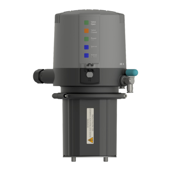
SPX FLOW SPX FLOW_CU4 plus.. AS-interface_IECEx_Zone 2_GB-1_012024_for D4. Valves.indd General Terms 3.3. Function of the individual components The installation of the control unit is undertaken by special adapters which are available for the different valves types, see chapter 5. Adapter. The snap connectors for supply air and pneumatic air to the individual cylinders at the valves are located at the outside of the control unit. - Page 18 SPX FLOW SPX FLOW_CU4 plus.. AS-interface_IECEx_Zone 2_GB-1_012024_for D4. Valves.indd General Terms 3.3. Function of the individual components The luminous diodes are located on the front side of the electronic module. Their signals are visibly indicated to the outside by an optical window in the cover the control unit. Beside the open and closed valve position, the existence of the operating voltage as well as different diagnostic information are indicated.
-
Page 19: Mechanics And Pneumatics
SPX FLOW SPX FLOW_CU4 plus.. AS-interface_IECEx_Zone 2_GB-1_012024_for D4. Valves.indd Mechanics and Pneumatics 4.1. Air connections for double seat mix proof valves 4.1.1. Function CU41plus-D4 design for D4 double seat mix proof valves without seat lift function air supply with integrated particle filter control air connection for main actuator exhaust air with silencer CU43plus-D4 design for D4 SL double seat mix proof valves with seat lift function air supply with integrated particle filter control air connection for main actuator pneumatic air connection for seat lift actuator of upper seat lifting pneumatic air connection for seat lift actuator of lower seat lifting... -
Page 20: Functional Description - Block Diagrams
SPX FLOW SPX FLOW_CU4 plus.. AS-interface_IECEx_Zone 2_GB-1_012024_for D4. Valves.indd Mechanics and Pneumatics 4.3. Functional description - block diagrams 4.3.1. CU41plus-D4 for D4 double seat mix proof valves without seat lift function AS-i Bus + AS-i Bus + AS-i Bus - AS-i Bus - Operating directions of valve targets LED 6 main stroke down M1 + M2... - Page 21 SPX FLOW SPX FLOW_CU4 plus.. AS-interface_IECEx_Zone 2_GB-1_012024_for D4. Valves.indd Mechanics and Pneumatics 4.3. Functional description - block diagrams 4.3.2. CU43plus-D4 for D4 SL double seat mix proof valves with seat lift function AS-i Bus + AS-i Bus + AS-i Bus - AS-i Bus - Operating directions of valve targets LED 6 PELV E + main stroke down...
-
Page 22: Technical Data / Standards
SPX FLOW SPX FLOW_CU4 plus.. AS-interface_IECEx_Zone 2_GB-1_012024_for D4. Valves.indd Mechanics and Pneumatics 4.4. Technical data / Standards Material: PA6.6/PA12 Ambient temperature: 0°C to +55°C (limitation due to ATEX application) EMC 2014/30/EU (89/336/EEC) Standards and environmental audits: protective class IP 64 EN 60529 EMC interference resistance EN 61000-6-2 EMC emitted interference EN 61000-6-4 AS-interface certification according to specification V3.0... -
Page 23: Solenoid Valves
SPX FLOW SPX FLOW_CU4 plus.. AS-interface_IECEx_Zone 2_GB-1_012024_for D4. Valves.indd Mechanics and Pneumatics 4.5. Solenoid valves In the base of the control unit max. 3 solenoid valves are installed. solenoid valve The 3/2-way solenoid valves are connected with the electronic block 1 module by moulded cables and plug connector. control: PWM signal handle:... -
Page 24: Adapter
SPX FLOW SPX FLOW_CU4 plus.. AS-interface_IECEx_Zone 2_GB-1_012024_for D4. Valves.indd Adapter Adapter for Double seat mix proof valves D4, D4 SL Control Unit CU4plus AS-interface IECEx ATEX Zone 2 Gas for D4/D4 SL Valves IECEx ATEX Zone 2 Gas Instruction Manual GB-1... -
Page 25: Electronic Module
SPX FLOW SPX FLOW_CU4 plus.. AS-interface_IECEx_Zone 2_GB-1_012024_for D4. Valves.indd Electronic Module 6.1. Function/block diagram The CU4plus AS-i control unit is a slave for the fieldbus system AS-Interface according to specification V3.0. The profile is S-7.A.*.E (3 outputs and 2/4 inputs). The CU4plus AS-i is designed for the extended address range. With these devices in the extended address range up to 62 slaves (formerly known as 2.1) can be connected with one AS-Interface cable. -
Page 26: Functional Description Of Connections
SPX FLOW SPX FLOW_CU4 plus.. AS-interface_IECEx_Zone 2_GB-1_012024_for D4. Valves.indd Electronic Module 6.2. Functional description of connections Terminal Designation Functional Description AS-i + connection AS-i network AS-i - connection AS-i network bridge Z+ / PELV E+ (in case of energy supply for solenoid valves via AS-i bus) bridge Z- / PELV E - (in case of energy supply for solenoid valves via AS-i bus) PELV E+ separate auxiliary energy PELV 24VDC + (for EMERGENCY STOP function, only) -
Page 27: Technical Data / As-Interface
SPX FLOW SPX FLOW_CU4 plus.. AS-interface_IECEx_Zone 2_GB-1_012024_for D4. Valves.indd Electronic Module 6.3. Technical data / AS-interface AS-interface-profile: S-7.A.*.E Extended address mode: is supported Serial communication mode: Inverse-polarity protection: exists Indication "Power": LED 3 (green) Indication "Fault": LED 4 (red) AS-interface voltage range: 26.5…31.6 V External voltage supply PELV 24 VDC max. current consumption: 100 mA (in case of supply of actuators from auxiliary energy) 150 mA (in case of supply of actuators from AS-interface) Input delay time:... -
Page 28: Connections
SPX FLOW SPX FLOW_CU4 plus.. AS-interface_IECEx_Zone 2_GB-1_012024_for D4. Valves.indd Electronic Module 6.4. Connections Sensors for valve position detection: Internal sensors: internal linear sensor SPX FLOW type switching distance acc. to SPX FLOW specification Internal hall sensors: "magnetic hall sensor" SPX FLOW UB 4.75 - 5.25 VDC switching distance acc. to SPX FLOW specification External sensors: inductive proximity switch... - Page 29 SPX FLOW SPX FLOW_CU4 plus.. AS-interface_IECEx_Zone 2_GB-1_012024_for D4. Valves.indd Electronic Module 6.5.1. LED indication / Indicator lights solenoid valve 2 / solenoid valve 2 controlled blue, 1 blink upper seat lift upper seat * lifted LED 1 solenoid valve 3 / solenoid valve 3 controlled blue, 2 blinks lower seat lift lower seat * lifted LED 2...
-
Page 30: Adjustement Of Valve Profiles
SPX FLOW SPX FLOW_CU4 plus.. AS-interface_IECEx_Zone 2_GB-1_012024_for D4. Valves.indd Electronic Module 6.6. Adjustement of valve profiles The adjustment of valve profiles is carried out with the Service Software CU4plus Toolbox (see CU4plus Toolbox manual). For the different process valves different logic profiles exist. These differ in view of the detection of the feedback and the logic profile of the valve. -
Page 31: Data Signals
SPX FLOW SPX FLOW_CU4 plus.. AS-interface_IECEx_Zone 2_GB-1_012024_for D4. Valves.indd Electronic Module 6.7. Data signals 6.7.1. Mix proof valve D4 operating main stroke downwards main stroke valve operating direction: downwards lower shaft signal S3 linear sensor 1 valve target signal S4 upper shaft signal S2 linear sensor 2 valve target signal S1 pressure sensor linear sensor 1 linear sensor 2 Output valve linear sensor 2 / (Teach data) linear sensor 1 / (Teach date) tolerance signals status... - Page 32 SPX FLOW SPX FLOW_CU4 plus.. AS-interface_IECEx_Zone 2_GB-1_012024_for D4. Valves.indd Electronic Module 6.7. Data signals 6.7.2. Mix proof valve D4 SL operating main stroke downwards upper seat lift upwards lower seat lift downwards main stroke valve operating direction: downwards lower shaft signal S3 linear sensor 1 valve target signal S4 upper shaft signal S2 linear sensor 2 valve target signal S1 pressure sensor linear sensor 1 linear sensor 2 Output valve status linear sensor 2 / (Teach data) linear sensor 1 / (Teach data) tolerance...
-
Page 33: Service And Maintenance Software Cu4Plus Toolbox
SPX FLOW SPX FLOW_CU4 plus.. AS-interface_IECEx_Zone 2_GB-1_012024_for D4. Valves.indd Electronic Module 6.7. Data signals 6.7.3. AS-i communication / AS-i parameter data / status / diagnosis AS-i parameter data (inverted) inputs outputs not occupied not occupied Teach mode not occupied Aux. Voltage not occupied Service requ. not occupied AS-i status inputs EEPROM error Automatic "unique"... -
Page 34: Seat Pulsation - Efficiency In Cleaning
SPX FLOW SPX FLOW_CU4 plus.. AS-interface_IECEx_Zone 2_GB-1_012024_for D4. Valves.indd Electronic Module 6.9. Seat Pulsation - Efficiency in Cleaning For increasing seat cleaning efficiency there is a function called "Pulsation". With this function, the seat lifts can be operated in plusation mode if the PLC signal activates the seat lift. For the pulsation the ON and OFF time can be adjusted with the CU4plus Toolbox. -
Page 35: Valve Position Indication
SPX FLOW SPX FLOW_CU4 plus.. AS-interface_IECEx_Zone 2_GB-1_012024_for D4. Valves.indd Valve Position Indication 7.1. Continuously measuring valve position measuring system For the internal detection of the valve position indication, a contact- free operating linear sensor is used which is actuated via the magnetic switching cam installed at the valve rod. The nominal measuring range of the measuring system amounts to 0 - 72 mm, relative repetitive accuracy <... -
Page 36: Adjustment Of Valve Position Indication / Teach-In
SPX FLOW SPX FLOW_CU4 plus.. AS-interface_IECEx_Zone 2_GB-1_012024_for D4. Valves.indd Valve Position Indication 7.3. Adjustment of valve position indication / Teach-in The continuously measuring valve position measuring system is tought via a reference valve movement. The respective positions for the closed and open valve position as well as for further valve positions, e.g. seat lifting, are travelled to and the corresponding position of the sensor system is permanently stored in the memory of the electronic module. -
Page 37: To Be Observed Before Teach-In
SPX FLOW SPX FLOW_CU4 plus.. AS-interface_IECEx_Zone 2_GB-1_012024_for D4. Valves.indd Valve Position Indication 7.5. To be observed before teach-in: Corresponding switching cam is mounted to the valve guide rod. Note! Caution! The switching cam is not identical with the standard CU switching cam! CU4plus AS-i control unit is not duly installed on the valve. Valve is duly installed in the process. -
Page 38: Cu Assembly And Startup
SPX FLOW SPX FLOW_CU4 plus.. AS-interface_IECEx_Zone 2_GB-1_012024_for D4. Valves.indd CU Assembly and Startup 8.1. Double seat mix proof valves D4, D4 SL CU cover pressure linear sensor CU41/CU43plus sensor operating cam with magnet M1 linear sensor stop screw thrust ring operating cam with magnet M2 screws clamp ring adapter actuator Assembly of the control unit on the valve 1. - Page 39 SPX FLOW SPX FLOW_CU4 plus.. AS-interface_IECEx_Zone 2_GB-1_012024_for D4. Valves.indd CU Assembly and Startup 8.1.1 Pneumatic connection Supply air: Caution! Shut off the compressed air supply before connecting the air hose! Make sure that the air hose is professionally cut to length. Use a hose cutter for this purpose. Pneumatic air to valve actuator: Connect pneumatic air connection Y1 with the valve actuator, air connection 1 - main stroke...
- Page 40 SPX FLOW SPX FLOW_CU4 plus.. AS-interface_IECEx_Zone 2_GB-1_012024_for D4. Valves.indd CU Assembly and Startup 8.4.3 Connection of external proximity switches The electric connection of the proximity switches specified by solenoid valve SPX FLOW is undertaken according to the terminal layout block 3 described in chapter 6. The mechanic assembly of the proximity switches is carried out at the actuator of the corresponding double seat valves.
-
Page 41: Accessories And Tools
SPX FLOW SPX FLOW_CU4 plus.. AS-interface_IECEx_Zone 2_GB-1_012024_for D4. Valves.indd Accessories and Tools Assembly/disassembly - adapter on valve actuator: • hexagon socket wrench 6 mm • screwdriver 4 mm Assembly/disassembly – CU on adapter: • hexagon socket wrench 3 mm Assembly/disassembly – electronic module: • Torx wrench TX20 • screwdriver 3.5 mm Assembly/disassembly – feedback unit: • Torx wrench TX15 Assembly/disassembly – electronic modules: •... -
Page 42: 10. Service
SPX FLOW SPX FLOW_CU4 plus.. AS-interface_IECEx_Zone 2_GB-1_012024_for D4. Valves.indd 10. Service 10.1. Dismantling Before disassembly, verify the following items: • The valve must be in safety position and must not be controlled! • Shut off air supply! • Cut off current to control unit, i.e. interrupt the supply voltage! Solenoid valve (4, 5, 6) Open the CU cover by turning in anticlockwise direction. -
Page 43: 11. Trouble Shooting
SPX FLOW SPX FLOW_CU4 plus.. AS-interface_IECEx_Zone 2_GB-1_012024_for D4. Valves.indd 11. Trouble Shooting Failure Remedy Valve position is not indicated. Carry out teach-in. Check fastening of magnetic switching cam. Check adjusted logic profile and process valve. Feedback via proximity Check positioning of proximity switches is missing. -
Page 44: 12. Iecex / Ccc Certificate Of Conformity
SPX FLOW SPX FLOW_CU4 plus.. AS-interface_IECEx_Zone 2_GB-1_012024_for D4. Valves.indd 12. IECEx / CCC Certificate of Conformity Please see attachment. 13. Spare Parts Lists The reference numbers of spare parts for the different control unit designs and adapters are included in the attached spare parts drawings with corresponding lists. When you place an order for spare parts, please indicate the following data: number of parts required... - Page 46 IECEx Certificate of Conformity INTERNATIONAL ELECTROTECHNICAL COMMISSION IEC Certification System for Explosive Atmospheres for rules and details of the IECEx Scheme visit www.iecex.com Certificate No.: IECEx TUN 22.0020X Page 1 of 3 Certificate history: Current Status: Issue No: 0 Date of Issue: 2023-09-11 Applicant: SPX Flow Technology Germany GmbH...
- Page 47 IECEx Certificate of Conformity Certificate No.: IECEx TUN 22.0020X Page 2 of 3 Date of issue: 2023-09-11 Issue No: 0 Manufacturer: SPX Flow Technology Germany GmbH Gottlieb-Daimler-Str. 13 59439 Holzwickede Germany SPX Flow Technology Germany SPX Flow Technology Poland Sp. z Manufacturing locations: GmbH...
- Page 48 IECEx Certificate of Conformity Certificate No.: IECEx TUN 22.0020X Page 3 of 3 Date of issue: 2023-09-11 Issue No: 0 EQUIPMENT: Equipment and systems covered by this Certificate are as follows: Description: The control unit type CU4** resp. CU4*plus* is provided for controlling process valves in hazardous areas, it used as an interface between the process control and the process valve and operates the electrical and pneumatic signals.
- Page 49 TÜV NORD CERT GmbH Hannover Office Am TÜV 1 30519 Hannover Germany Page 1 of 5 Attachment to IECEx TUN 22.0020X issue No.: 0 General product information: Description: The control unit type CU4** resp. CU4*plus* is provided for controlling process valves in hazardous areas, it used as an interface between the process control and the process valve and operates the electrical and pneumatic signals.
- Page 50 TÜV NORD CERT GmbH Hannover Office Am TÜV 1 30519 Hannover Germany Page 2 of 5 Attachment to IECEx TUN 22.0020X issue No.: 0 Electrical data: For the control unit type CU4* plus AS-interface Internal / External Terminal Designation Functional description External AS-i + Connection AS-i network (26.5 V…31.6 V d.c.)
- Page 51 TÜV NORD CERT GmbH Hannover Office Am TÜV 1 30519 Hannover Germany Page 3 of 5 Attachment to IECEx TUN 22.0020X issue No.: 0 For the control unit type CU4* plus 24V Direct Connect: Internal / External Terminal Designation Functional description External Power+ Power supply 24V d.c.
- Page 52 TÜV NORD CERT GmbH Hannover Office Am TÜV 1 30519 Hannover Germany Page 4 of 5 Attachment to IECEx TUN 22.0020X issue No.: 0 For the control unit type CU4*24V Direct Connect: Internal / External Terminal Designation Functional description External Power+ Power supply 24V d.c.
- Page 53 TÜV NORD CERT GmbH Hannover Office Am TÜV 1 30519 Hannover Germany Page 5 of 5 Attachment to IECEx TUN 22.0020X issue No.: 0 Thermal data: Control unit type CU4** resp. CU4*plus*: Permissible ambient temperature range during operation: 0 °C ≤ Ta ≤ +55 °C Double seat valve type D4*: The permissible ambient temperature range as process temperature (medium or cleaning solutions temperature) depending on the temperature class is shown in the following table:...
- Page 55 No.:2023312304001783 SPX(Shanghai) Flow Technology Company Limited Applicant No.666, Fengjin Road, Xidu Industry park, Fengxian District, Address Shanghai China SPX Flow Technology Poland Sp. z o.o. Manufacturer Stanisława Rolbieskiego 2, Bydgoszcz 85-862, Poland Address SPX Flow Technology Poland Sp. z o.o. Production Factory Stanisława Rolbieskiego 2, Bydgoszcz 85-862, Poland Production Address...
- Page 56 No.:2023312304001783 Page 1 of 8 Product information: This certificate covers the following models: - CU4** , CU4*plus* Nomenclature: 1) CU4** 1: 1 solenoid 2: 1 solenoid, 1NOT element 3: 3 solenoids AS-interface 24V Direct Connect 2) CU4*plus* plus 1: 1 solenoid 2: 1 solenoid, 1NOT element 3: 3 solenoids AS-interface...
- Page 57 No.:2023312304001783 Page 2 of 8 Control unit type CU4*AS-interface Internal / Terminal Designation Functional description External External AS-i + Connection AS-i network (26.5 V…31.6 V d.c.) External AS-i - Connection AS-i network (GND) Internal 5 VDC Voltage supply for proximity switches Internal Sensor 1 Signal sensor 1 (closed valve position)
- Page 58 No.:2023312304001783 Page 3 of 8 External SV Digital Output Common External DI0 Digital Input PLC output to activate solenoid 1 / main valve External DI1 Digital Input PLC output to activate solenoid 2 / upper seat lift External PLC output to activate solenoid 3 / lower DI2 Digital Input seat lift External...
- Page 59 No.:2023312304001783 Page 4 of 8 Internal Bridge Z+ / PELV E+ (in case of energy supply for solenoid valves via AS-i bus) Internal Bridge Z- / PELV E - (in case of energy supply for solenoid valves via AS-i bus) Internal PELV E+ Separate auxiliary energy PELV 24VDC + (for...
- Page 60 No.:2023312304001783 Page 5 of 8 Internal Solenoid valve 3 (lower seat lift) Internal Optional connection - pressure sensor External Service port Connection serial/USB converter for CU4plus toolbox software Control unit type CU4* plus 24V Direct Connect Internal / Terminal Designation Functional description External External...
- Page 61 No.:2023312304001783 Page 6 of 8 Internal Signal SPX prox. sensor Internal Potential for SPX prox. sensor / linear sensor Internal Linear sensor Internal PWM Output Solenoid valve 1 (main valve) Internal PWM Output Solenoid valve 2 (upper seat lift) Internal PWM Output Solenoid valve 3 (lower seat lift) External...
- Page 62 No.:2023312304001783 Page 7 of 8 Internal Sensor 1 Linear Sensor 1 Internal Sensor 2 Sensor Signal 2 Internal Mass potential for sensor supply Internal PWM Output Solenoid valve 1 (main valve) Internal PWM Output Solenoid valve 2 (upper seat lift) Internal PWM Output Solenoid valve 3 (lower seat lift)
- Page 63 No.:2023312304001783 Page 8 of 8 - Measures have to be taken, external to the control unit type CU4** resp. CU4*plus*, to provide a transient protection that ensures that the rated voltage, connected to the power supply terminals, is not exceeded by more than 40%. - See instruction for other information.
- Page 74 Design features, materials of construction and dimensional data, as described in this manual, are provided for your information only and should not be relied upon unless confirmed in writing. Please contact your local sales representative for product availability in your region. For more information visit www.spxflow.com. ISSUED 06/2023 - Original Manual...
Need help?
Do you have a question about the APV CU4 plus and is the answer not in the manual?
Questions and answers