Table of Contents
Advertisement
Quick Links
Advertisement
Table of Contents

Related Manuals for SPXFLOW CU4plus


Summary of Contents for SPXFLOW CU4plus
- Page 1 I N S T R U C T I O N M A N U A L Control Unit CU4plus IO-Link C o n t r o l U n i t F O R M N O . : H 3 4 6 2 5 1 R E V I S I O N : G B - 3 R E A D A N D U N D E R S TA N D T H I S M A N U A L P R I O R TO O P E R AT I N G O R S E RV I C I N G T H I S P R O D U C T.
-
Page 5: Table Of Contents
Adjustement of valve profiles 6.9. Data signals 6.10. Data Storage Mode / Firmware Update 6.11. Seat Pulsation - Efficiency in Cleaning 6.12. Service and Mainenance Software CU4plus Toolbox 6.13. Data Acquisition and BLOB Data Transfer 6.14. Valve Monitoring Valve Position Indication 7.1. Continuously measuring valve position measuring system 7.2. -
Page 6: Abbreviations And Definitions
These special safety instructions point directly to the respective handling instructions. They are accentuated by the corresponding symbol. Carefully read the instructions to which the sentinels refer. Continue handling the control unit only after having read these instructions. Control Unit CU4plus IO-Link Instruction Manual GB-3... -
Page 7: Intended Use
Safety Instructions 2.2. Intended use The CU4plus IO-Link control unit is only intended for use as described in chapter 3.1. Use beyond that described in chapter 3.1. do not comply with the regulations and SPX FLOW shall not be responsible for any damage resulting from this non-observance. -
Page 8: Welding Instructions
Prerequisite for a guarantee is the correct use of the unit in compliance with the specified conditions of application. Note! This warranty only applies to the Control Unit. No liability will be accepted for consequential damage of any kind arising from failure or malfunction of the device. Control Unit CU4plus IO-Link Instruction Manual GB-3... -
Page 9: General Terms
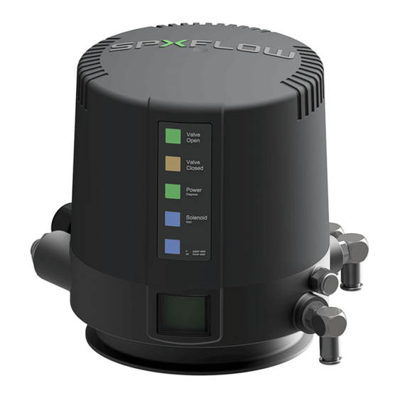
General Terms 3.1. Purpose of use fig. 3.2. The control unit CU4plus IO-Link has been developed for the control of process valves in food processing industry as well as related industries. The CU4plus IO-Link control unit operates as interface between process control and process valve and controls the electric and pneumatic signals. - Page 10 The air supply of the control unit is equipped with an exchangeable air filter. Observance of the required compressed air quality is imperative. Please also see chapter 4.5 Technical Data. The number of the solenoid valves installed in the CU4plus depends on the valve actuators to be controlled. Single seat and butterfly valves and double seat valves without seat lift function require 1 solenoid valve.
-
Page 11: Function Of The Individual Components
The complete control unit has been designed on the building block principle. By exchange of the electronic module, the control type can be changed, e.g. from direct control (Direct Connect) to communication with AS-Interface or IO-Link. Note! Wiring must be changed! Control Unit CU4plus IO-Link Instruction Manual GB-3... -
Page 12: Mechanics And Pneumatics
Y2 pneumatic air connection for seat lift actuator of upper seat lifting Y3 pneumatic air connection for seat lift actuator of lower seat lifting A1/A2 exhaust air with silencer Control Unit CU4plus IO-Link Instruction Manual GB-3... - Page 13 AIR IN A1/A2 exhaust air, with exhaust silencer Control Unit CU4plus IO-Link Instruction Manual GB-3...
-
Page 14: Pressure Relief Valve
If required, the pressure relief valve vents into the clearance between the base and the adapter of the control unit. The pressure relief valve must not be mechanically blocked under any circumstances. DANGER DANGER Control Unit CU4plus IO-Link Instruction Manual GB-3... - Page 15 LED 1 JST Sensor 1 Teach function and saved in the control unit. linear sensor solenoid valve throttle valves P / air supply A / exhaust pressure sensor Control Unit CU4plus IO-Link Instruction Manual GB-3...
-
Page 16: Functional Description - Block Diagrams
Teach function and saved in the control unit. linear sensor pressure reducing valve (locked to 5 bar) self-lock solenoid valve connector throttle valves P / air supply A / exhaust pressure sensor NOT element Control Unit CU4plus IO-Link Instruction Manual GB-3... - Page 17 LED 1 JST Sensor 1 pressure linear sensor (Y) sensor A / exhaust P / air supply sol. valve 1 sensor 3 sol. valve 2 sensor 4 A / exhaust sol. valve 3 sensor 1 (Teach signal) sensor 2 (Teach signal) Control Unit CU4plus IO-Link Instruction Manual GB-3...
- Page 18 (in sensor tower, upper part) (connected with sensor 2 e-module) linear sensor (in sensor tower, lower part) (connected with plug e-module) pressure sensor solenoid valve throttle valves P / air supply A / exhaust air Control Unit CU4plus IO-Link Instruction Manual GB-3...
- Page 19 (in sensor tower, upper linear sensor part) (in sensor tower, (connected lower part) with sensor 2 (connected with e-module) sensor 1 e-module) pressure sensor exhaust air sol. 1 sol. 2 exhaust air sol. 3 Control Unit CU4plus IO-Link Instruction Manual GB-3...
- Page 20 (in sensor linear sensor tower, upper (in sensor tower, part) lower part) (connected (connected with with sensor 2 sensor 1 e-module) e-module) pressure sensor exhaust air sol. 1 sol. 2 exhaust air sol. 3 Control Unit CU4plus IO-Link Instruction Manual GB-3...
- Page 21 12 Sensor 2 M2 - magnet lower shaft 13 GND LED 1 JST Sensor 1 pressure sensor external linear sensor exhaust air air supply sol. 1 sol. 2 exhaust air sol. 3 internal linear sensor Control Unit CU4plus IO-Link Instruction Manual GB-3...
-
Page 22: Technical Data / Standards
1, max. 0,01 mg/m³ The oil applied must be compatible with Polyurethane elastomer materials. Control Unit CU4plus IO-Link Instruction Manual GB-3... -
Page 23: Solenoid Valves
The air hose must be slided into the air connection until it stops in order to open the non-return valve. solenoid valve block 1 The NOT element is also used for air/air - actuators. with NOT element Control Unit CU4plus IO-Link Instruction Manual GB-3... -
Page 24: Adapter
Adapter for different process valves 5.1. Valves with turning actuator, e.g. butterfly valve 5.2. Single seat valve 5.3. Double seat mix proof valve DE3, DA3+ 5.4. Double seat mix proof valves D4, D4 SL, D4 PMO, DA4 Control Unit CU4plus IO-Link Instruction Manual GB-3... -
Page 25: Double Seat Tank Outlet Valve Dt4 Sl
SPX FLOW SPX FLOW_CU4plus_IO-Link_GB-3_112023_CE_UKCA.indd Adapter Adapter for different process valves 5.5. Double seat tank outlet valve DT4 SL 5.5.1. DT4 - 62 adapter 5.5.2. DT4 - 92 adapter Control Unit CU4plus IO-Link Instruction Manual GB-3... -
Page 26: Electronic Module
SPX FLOW_CU4plus_IO-Link_GB-3_112023_CE_UKCA.indd Electronic Module 6.1. Function/block diagram The electronic module CU4plus IO-Link operates as interface between superordinated control (PLC) and is connected to the PLC via an IO-Link master. The connection is accomplished by a 3-wire cable with a M12 plug. The input voltage and the signal is transferred by this cable. Both in accordance with the IO-Link specification. - Page 27 2 prox. LED 3/4 Teach-in LED 8 function LED 7 sensor 3 NI5-K11K-AN5X/5 11 5VDC LED 2 12 Sensor 2 NI5-K11K-AN5X/5 connection 13 GND sensor 4 for toolbox LED 1 JST Sensor 1 Control Unit CU4plus IO-Link Instruction Manual GB-3...
- Page 28 LED 5 start LED 9 LED 3/4 Teach-in LED 8 function LED 7 brown 11 5VDC LED 2 green 12 Sensor 2 connection white 13 GND for toolbox LED 1 JST Sensor 1 Control Unit CU4plus IO-Link Instruction Manual GB-3...
-
Page 29: Functional Description Of Connections
Sensor Signal 2 Sensor 2 Mass potential for sensor supply PWM Output Solenoid valve 1 (main valve) PWM Output Solenoid valve 2 (upper seat lift) PWM Output Solenoid valve 3 (lower seat lift) Connection serial/USB converter for CU4plus toolbox service port Pressure sensor Pressure measurement of main actuator Control Unit CU4plus IO-Link Instruction Manual GB-3... -
Page 30: Technical Data
(Power ON, 3 LED, 1 solenoid valve, 2 Sensors) Maximum about 105 mA @ 24VDC (Power ON, 3 LED, 2 solenoid valves, 2 Sensors) Cable Length max. 20 m (IO-Link specific) Connecting terminals: conductor cross section 0.5 – 1.5 mm² (with conductor sleeve) complying with AWG 20-16 Firmware update: by encrypted *.iolfw file Control Unit CU4plus IO-Link Instruction Manual GB-3... -
Page 31: Connections
Separate option for manual calibration of valve closed position IO-Link approvals: IEC 611 31-9 Physical layer test Device Conformance test Control instruments: IEC 60947-5-2 6.5. Configuration IODD-File: Can be download from: https://ioddfinder.io-link.com/ Vendor IO: 13763 Device ID: Control Unit CU4plus IO-Link Instruction Manual GB-3... -
Page 32: 6.6. Led Indication / Indicator Lights
Air pressure low LED 8 Service request color red Teach procedure active LED 9 color red, flashing no valid teach data Internal luminous displays Luminous diode 1st solenoid valve (1) controlled Luminous diode 2nd solenoid valve (2) controlled Luminous diode 3rd solenoid valve (3) controlled Control Unit CU4plus IO-Link Instruction Manual GB-3... - Page 33 6.6. LED indication / Indicator lights Process Signal (from FW-V2.00) All LED´s Running light with all led´s LED signal blink Indicate a CU4plus in the field color green Air pressure ok Air pressure ok LED 7 color green, flashing Air pressure fail...
-
Page 34: 6.7. Wiring
A cable with a core cross-sectional area of 0,35 mm² and a length of up to 20 m can be used to connect the IO-Link master and the CU4plus IO-Link. No special calculation is required in this case. Nevertheless, the supply cables between the power supply unit and the IO-Link master should be checked for voltage drops. -
Page 35: Adjustement Of Valve Profiles
Valve position indication: LED can be inverted, e.g. for adaption of valve type Restore factory settings: Mix proof valve DA4 profile is adjusted. Adjusted valve characteristics: logic profile 1, for DA3+ with SLD Teach-in: CU waits for Teach-in with valve, LED 3-6 blink Adjustment / change of valve profile is realized via the IO-Link Master in the parameter area. Control Unit CU4plus IO-Link Instruction Manual GB-3... - Page 36 1 sensor 2 Output signals signal generated by Teach-in signal generated by Teach-in (position of position sensor) (position of position sensor) closed open not occupied not occupied solenoid 1 Main solenoid 2 solenoid 3 Input signals Control Unit CU4plus IO-Link Instruction Manual GB-3...
- Page 37 4 sensor signals. The appropriate valve position is shown direct by the output signals. Further ajdustments are not required! solenoid 1 solenoid 2 solenoid 3 main upper seat lower seat Input signals lift lift When replacing a CU3 control unit, use the following profile: CU3 compatible mode Double seat mix proof valve with seat lift detection (SLD) (all signals similar to CU3) - see instruction manual of CU3 Control Unit. Control Unit CU4plus IO-Link Instruction Manual GB-3...
- Page 38 S2 sensor signal S3 closed not used +1 mm, -1 mm open +1 mm, not used -1 mm Input signal solenoid 1 solenoid 1 solenoid 1 Main upper seat lift lower seat lift Control Unit CU4plus IO-Link Instruction Manual GB-3...
- Page 39 +1 mm, -1 mm upper seat lift +1 mm, -1 mm lower seat lift +1 mm, -1 mm Input signal solenoid 1 solenoid 2 solenoid 3 Main upper seat lift lower seat lift Control Unit CU4plus IO-Link Instruction Manual GB-3...
- Page 40 - the opposite valve shaft stays in closed position, this can be monitored by watching the appropriate signal Digital Input solenoid 1 solenoid 2 solenoid 3 data Main upper seat lift lower seat lift Control Unit CU4plus IO-Link Instruction Manual GB-3...
- Page 41 +1 mm, -1 mm upper seat lift +1 mm, -1 mm lower seat lift +1 mm, -1 mm Input signals solenoid 1 solenoid 2 solenoid 3 Main upper seat lift lower seat lift Control Unit CU4plus IO-Link Instruction Manual GB-3...
- Page 42 +1 mm, -1 mm upper seat lift +1 mm, -1 mm lower seat lift +1 mm, -1 mm Output solenoid 1 solenoid 1 solenoid 1 signals Main upper seat lift lower seat lift Control Unit CU4plus IO-Link Instruction Manual GB-3...
-
Page 43: Data Signals
External proximity switch 4 active Air Pressure Unsigned Air pressure of the main actuator integer Valve Shaft Position 1 Float Linear sensor 1 position Valve Shaft Position 2 Float Linear sensor 2 position Control Unit CU4plus IO-Link Instruction Manual GB-3... - Page 44 Boolean Service request present Air Pressure ok Boolean Air pressure ok Air Pressure fail Boolean Air Pressure error Valve Monitor Error Unsigned Valve Monitor failure values: integer Bit 0 (0x01) EMV1 on error Bit 1 (0x02) EMV1 off error Bit 3 ( 0x04) EMV2 on error Bit 4 ( 0x08) EMV2 off error Bit 5 ( 0x10) EMV3 on error Bit 6 ( 0x20) EMV3 off error Control Unit CU4plus IO-Link Instruction Manual GB-3...
- Page 45 The valve must be activated with the signal ‘Upper Seatlift”. Lower seat pulsation Switching the pulsation mode on for lower Boolean seat lift. The valve must be activated with the signal ‘Lower Seatlift”. Control Unit CU4plus IO-Link Instruction Manual GB-3...
- Page 46 SPX Flow Technology Germany GmbH Vendor Text String www.spxflow.com Product Name String CU4plus IO-Link Product ID String H344393 Product Text String Control Unit CU4plus IO-Link Serial Number String Hardware Version String Firmware Version String Application Specific Tag String Freely selectable Function Tag String...
- Page 47 Unsigned Integer 6.9.16. System Parameter Name Index Subindex Rights Type Unit Valve Type Unsigned Integer Solenoid Amount Unsigned Integer LED Display Unsigned Integer Pressure Sensor Unsigned Integer Tolerance Unsigned Integer Operating Principle Unsigned Integer Control Unit CU4plus IO-Link Instruction Manual GB-3...
- Page 48 AM1-Valve (Aseptic Mix Proof Valve) Parameters Name Index Subindex Rights Type Unit Idle time for the upper seat lift Unsigned Integer signal Pressure level to suppress Unsigned Integer the upper seat lift signal Control Unit CU4plus IO-Link Instruction Manual GB-3...
- Page 49 1, 2, 5, 10 integer 1 hour Delay for next trigger start Unsigned hours integer days 2 hours 6 hours 12 hours 1 day 7 days 14 days 21 days 30 days 90 days 180 days Control Unit CU4plus IO-Link Instruction Manual GB-3...
- Page 50 ERROR: Overlap prea position S1 LIN_SENSOR_OVERLAP_S2 ERROR 181f ERROR: Overlap area position S2 LIN_SENSOR_OVERLAP_LIFT ERROR 1820 ERROR: Overlap area position LIFT LIN_SENSOR_OVERLAP_S3 ERROR 1821 ERROR: Overlap area position S3 LIN_SENSOR_OVERLAP_S4 ERROR 1822 ERROR: Overlap area position S4 Control Unit CU4plus IO-Link Instruction Manual GB-3...
- Page 51 1845 Notification: Max. reaction time deactivation exceeded TIME_DE CATION VALELOGIC_SERVICE_MIN_AIR NOTIFI 1846 Notification: Air pressure low CATION VALELOGIC_SERVICE_MAX_AIR NOTIFI 1847 Notification: Air pressure high CATION VALELOGIC_SERVICE_EVENT NOTIFI 1848 Notification: Service event occurred CATION Control Unit CU4plus IO-Link Instruction Manual GB-3...
- Page 52 Teach: Activate actuator 2 (Solenoid 2). CATION TEACH_INFO_WAIT_SEAT_UPPER NOTIFI- 1897 Teach: Wait until upper seatlift position is reached. CATION TEACH_INFO_CLOSE_VALVE_2 NOTIFI- 1898 Teach: Deactivate Actuator 2 (Solenoid 2). CATION TEACH_INFO_WAIT_POS_1_2 NOTIFI- 1899 Teach: Deactivate actuator 2. Waiting for valve position CATION is reached. Control Unit CU4plus IO-Link Instruction Manual GB-3...
- Page 53 Teach: Sensor 1 out of range CATION TEACH_SENSOR2_OUT_OF_RANGE NOTIFI- 18a9 Teach: Sensor 2 out of range CATION TEACH_STORE_SENSOR2_S3 NOTIFI- 18aa Teach: Record Sensor 2 Position 3 CATION TEACH_STORE_SENSOR2_S4 NOTIFI- 18ab Teach: Record Sensor 2 Position 4 CATION Control Unit CU4plus IO-Link Instruction Manual GB-3...
- Page 54 NOTIFI- 18ab Teach: Record Sensor 2 Position 4 CATION Event Event IODD Text Type Code Special for IO-Link device test TEST_EVENT_A ERROR 8DFE TEST_EVENT_B ERROR 8DFF parameter_error ERROR 6320 DS_UPLOAD_REQUEST NOTIFI- FF91 CATION Control Unit CU4plus IO-Link Instruction Manual GB-3...
-
Page 55: Data Storage Mode / Firmware Update
Data Storage between Masters and Devices is specified according the IO-Link standard, whereas the adjacent upper data storage mechanisms depend on the individual fieldbus or system. The CU4plus IO-Link holds all for an device exchange needed parameters for Data Storage. CU4 plus supports all IO-Link target modes such as SCAN, TYPE COMPATIBLE and IDENTICAL mode. -
Page 56: Seat Pulsation - Efficiency In Cleaning
We recommend adjusting the time for "pulse off" to be larger than 30 seconds. When the seat pulsation is activated, with the 1st seat lifting (pulse on), the feedback signal for the appropriate seat lift will be active. PLC signal for seat pulsation solenoid signal for seat lift time time time puls. on puls. off Control Unit CU4plus IO-Link Instruction Manual GB-3... -
Page 57: Service And Mainenance Software Cu4Plus Toolbox
Electronic Module 6.12. Service and Mainenance Software CU4plus Toolbox For the parameterization of the CU4plus IO-Link the CU4plus Toolbox Software for PC is available. This is an alternative to the parameterization with the IO-Link connection. All parameters can be read and set in both ways. - Page 58 “Process Data Set 3”. And also a dataset for teach “TEACH Data”. 6.13.3. Data Format The data are split up into the following blocks: Data Set 0 Data Set 1 Data Set 2 Data Set 3 Teach Data Control Unit CU4plus IO-Link Instruction Manual GB-3...
- Page 59 LastActivationTime; LastReactionTimeAct; LastDeactivationTime; LastReactionTimeDeact; Interval Data Set Header <9 separated values> shaftPosition1; shaftPosition2; airPressure; digitalOutputs Start Valve Open Measurements Valve open values Data 200*<4 separated values> Start Valve Closing Measurements Valve closing values Data 200*<5 separated values> Control Unit CU4plus IO-Link Instruction Manual GB-3...
- Page 60 The digital output bits are also a combination displayed as hexadecimal digit. Bit conversion as follows: 0x80 0x40 0x20 0x10 0x08 0x04 0x02 0x01 Description Lower Upper Main seat lift seat lift Valve Control Unit CU4plus IO-Link Instruction Manual GB-3...
-
Page 61: Valve Monitoring
The error value is still available until the next valve switch. Or the error value can be reset with the ‘Reset Valve Monitor Error’ function. This valve monitor function doesn’t work with the levers at the solenoids! Control Unit CU4plus IO-Link Instruction Manual GB-3... - Page 62 Position controlled Pulsation on Unsigned integer time lower seatlift Pulse movement change position Unsigned integer main actuator Pulse movement change position Unsigned integer upper seat lift Pulse movement change position Unsigned integer lower seat lift Control Unit CU4plus IO-Link Instruction Manual GB-3...
-
Page 63: Valve Position Indication
D4 PMO, DA4, DT4 SL +/- 2 mm e.g. SW4, MS4 +/- 5 mm e.g. SV, SVS, DKR tolerance tolerance tolerance valve band band band stroke (mm) ± 1mm ± 2mm ± 5mm Control Unit CU4plus IO-Link Instruction Manual GB-3... -
Page 64: Adjustment Of Valve Position Indication / Teach-In
Teach-in key for 3 sec. Teach-in failure: LED 9 blink Check the tech events Compressed air is occurred at the IO-Link missing. master to diagnose the Supply voltage failure. missing. Switching logic does not fit to valve. Control Unit CU4plus IO-Link Instruction Manual GB-3... -
Page 65: Teach Closed Position
The IO-Link parameter "Teach Closed Position" index 94 starts this function. The assumption of this function is that the valve is closed. This means that all solenoid valves are off for a N.C. (normally closed) valve or the main solenoid valve is activated for a valve with N.O. (normally open) functionality. Control Unit CU4plus IO-Link Instruction Manual GB-3... -
Page 66: To Be Observed Before Teach-In
Note! Caution! The switching cam is not identical with the standard CU switching cam! CU4plus IO-Link control unit is not duly installed on the valve. Valve is duly installed in the process. Valve is not manually controlled or controlled by PLC. -
Page 67: Cu Assembly And Startup
2. Install switching cam with shaft rod prolongation. Secure with Loctite semi-solid and fasten it. 3. Place the control unit over the switching cam onto the adapter. Observe alignment. 4. Attach the clamp rings and fasten them with the screws. Control Unit CU4plus IO-Link Instruction Manual GB-3... - Page 68 1. Switch on the air supply. 2. Switch on the voltage supply. 3. Adjust corresponding logic profile in accordance with the process valve used (if this has not been determined for the delivery status). 4. Select Valve Type: Type 9 Single Seat, Butterfly Valves 5. Start Teach-in. It is mandatory to observe the corresponding prerequisites (see chapter 7.3.). Control Unit CU4plus IO-Link Instruction Manual GB-3...
-
Page 69: Single Seat Valve
2. Secure switching cam with Loctite semi-solid and fasten it. 3. Place the control unit over the switching cam onto the adapter. Observe alignment! 4. Attach the clamp rings and fasten them with the screws. Control Unit CU4plus IO-Link Instruction Manual GB-3... - Page 70 1. Switch on the air supply. 2. Switch on the voltage supply. 3. Adjust corresponding logic profile in accordance with the process valve used (if this has not been determined for the delivery status). 4. Select Valve Type: Type 9 Single Seat, Butterfly Valves 5. Start Teach-in. It is mandatory to observe the corresponding prerequisites (see chapter 7.3.). Control Unit CU4plus IO-Link Instruction Manual GB-3...
-
Page 71: Double Seat Valve Da3+ With Activated Seat Lift Detection (Sld)
4. Place the control unit onto the adapter. Observe alignment! 5. Attach air connections of the control unit to the valve actuator. 6. Attach the clamp rings and fasten them with the screws. 7. Assemble the external proximity switches at the actuator. Control Unit CU4plus IO-Link Instruction Manual GB-3... - Page 72 6. The mechanic assembly of the proximity switches is carried out at the actuator of the corresponding double seat valves. Observance of the instruction manual for double seat valves is essential! Control Unit CU4plus IO-Link Instruction Manual GB-3...
- Page 73 1. Switch on the air supply. 2. Switch on the voltage supply. 3. Adjust corresponding logic profile in accordance with the process valve used (if this has not been determined for the delivery status). 4. Select Valve Type: Type 6 DA3+ 5. Start Teach-in. It is mandatory to observe the corresponding prerequisites (see chapter 7.3.). Control Unit CU4plus IO-Link Instruction Manual GB-3...
-
Page 74: Double Seat Mix Proof Valves D4, D4 Sl, D4 Pmo, Da4
6. Place the control unit onto the adapter. Observe alignment! 7. Attach the clamp rings and fasten them with the 2 screws. 8. Attach air connections of the control unit to the valve actuator. Control Unit CU4plus IO-Link Instruction Manual GB-3... - Page 75 8.4.2 Electric connection Attention! Electric connections shall only be carried out by qualified personnel. Observe the Safety Instructions specified in chapter 2. Control Unit CU4plus IO-Link Instruction Manual GB-3...
- Page 76 3. Check the solenoid valves by turning the lever on the upper side by 90°. 4. Select Valve Type: Type 0 DA4 Type 1 D4 Type 2 D4 SL Type B PMO 5. For final adjustments of the feedback position switches please use the Teach function. Control Unit CU4plus IO-Link Instruction Manual GB-3...
-
Page 77: Double Seat Tank Outlet Valve Dt4 Sl
4. Place the control unit onto the adapter. Observe alignment! 5. Attach the clamp rings and fasten them with the 2 screws. 6. Align air connections of the control unit to the valve actuator. Control Unit CU4plus IO-Link Instruction Manual GB-3... - Page 78 8.5.2 Electric connection Attention! Electric connections shall only be carried out by qualified personnel. Observe the Safety Instructions specified in chapter 2. Control Unit CU4plus IO-Link Instruction Manual GB-3...
- Page 79 2. Switch on the voltage supply. 3. Check the solenoid valves by turning the lever on the upper side by 90°. 4. Select Valve Type: Type A DT4 5. For final adjustments of the feedback position switches please use the Teach function. Control Unit CU4plus IO-Link Instruction Manual GB-3...
-
Page 80: Accessories And Tools
Assembly/disassembly – electronic modules: • Torx wrench TX20 Assembly/disassembly – air connections: • jaw wrench SW13 Assembly/disassembly – pressure relief valve: • Torx wrench TX10 Loctite semi-solid jaw wrench torx wrench hexagon socket wrench screwdriver Control Unit CU4plus IO-Link Instruction Manual GB-3... -
Page 81: 10. Service
The linear sensor can only be replaced at the dismantled feedback unit. + Remove the 2 screws (14) TX10. Release the plug connection at the electronic module. Dismantle the linear sensor. Assembly in reverse order. Carry out Teach-in. Control Unit CU4plus IO-Link Instruction Manual GB-3... -
Page 82: Trouble Shooting
Check cabeling between electronic module and solenoid valve. Check compressed air (min. 6 bar). Bore for transfer of control air to turning actuator must be open. Air leakage at lower side of Check O-rings of adapter. adapter. Control Unit CU4plus IO-Link Instruction Manual GB-3... - Page 83 Check cabeling between electronic module and solenoid valve. Check compressed air (min. 6 bar) (D4 - min. 5 bar). Check control air connection between the CU43plus and the DA3 / DA4 / D4 SL / D4 PMO / DT4 SL actuator. Control Unit CU4plus IO-Link Instruction Manual GB-3...
-
Page 84: 12. Spare Parts Lists
When you place an order for spare parts, please indicate the following data: number of parts required ID number reference number parts designation Data are subject to change. Control Unit CU4plus IO-Link Instruction Manual GB-3... - Page 101 Design features, materials of construction and dimensional data, as described in this manual, are provided for your information only and should not be relied upon unless confirmed in writing. Please contact your local sales representative for product availability in your region. For more information visit www.spxflow.com. ISSUED 11/2023 - Original Manual...
Need help?
Do you have a question about the CU4plus and is the answer not in the manual?
Questions and answers