Advertisement
Quick Links
I N S T R U C T I O N M A N U A L
DA4
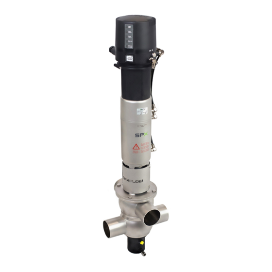
D O U B L E S E AT M I X P R O O F VA LV E
F O R M N O . : H 3 3 8 7 9 8
R E V I S I O N : U S - 2
R E A D A N D U N D E R S TA N D T H I S M A N U A L P R I O R TO O P E R AT I N G O R S E RV I C I N G T H I S P R O D U C T.
Advertisement

Subscribe to Our Youtube Channel
Related Manuals for SPXFLOW Waukesha Cherry-Burrell DA4


Summary of Contents for SPXFLOW Waukesha Cherry-Burrell DA4
- Page 1 I N S T R U C T I O N M A N U A L D O U B L E S E AT M I X P R O O F VA LV E F O R M N O . : H 3 3 8 7 9 8 R E V I S I O N : U S - 2 R E A D A N D U N D E R S TA N D T H I S M A N U A L P R I O R TO O P E R AT I N G O R S E RV I C I N G T H I S P R O D U C T.
- Page 3 Waukesha Cherry-Burrell brand DA4 Valve WCB_DA4_US-2_032020.indd Content Page General Terms Safety Symbols Safety Instructions Intended Use Mode of Operation 4.1. General terms 4.2. Valve in "closed" position 4.3. Valve in "open" position Control Units / Valve Position Indication 5.1. Control unit and adapter 5.2.
- Page 4 Waukesha Cherry-Burrell brand DA4 Valve WCB_DA4_US-2_032020.indd General Terms This instruction manual should be read carefully by the competent operating and maintenance personnel. We point out that we will not accept any liability for damage or malfunctions resulting from the non-compliance with this instruction manual.
- Page 5 Authorizations and External Approvals To view the certifications for this and other innovative SPX FLOW products, visit https://www.spxflow.com/en/waukesha-cherry-burrell/about-us/ certifications/ It is within the responsibility of the plant operator to evaluate and verify the suitability of SPX FLOW products for the intended...
- Page 6 Waukesha Cherry-Burrell brand DA4 Valve WCB_DA4_US-2_032020.indd Mode of Operation fig. 4.1 4.1. General terms Due to its construction and mode of operation as well as to the use of high quality stainless steel and adequate seal materials, the DA4 double seat mix proof valve is suited for applications in the food control unit and beverage industries as well as in pharmaceutical and chemical applications.
- Page 7 Waukesha Cherry-Burrell brand DA4 Valve WCB_DA4_US-2_032020.indd Mode of Operation fig. 4.2. 4.2. Valve in "closed" position The lower and upper valve shaft are in closed position and safely separate the different liquids A and B. The leakage chamber L, which is situated between the two valve shafts, provides for a free and depressurized discharge to the bottom.
- Page 8 Waukesha Cherry-Burrell brand DA4 Valve WCB_DA4_US-2_032020.indd Control Units / Valve Position Indication 5.1. Control unit and adapter An adapter is required to assemble the control unit on the DA4 valve. The following different designs are available: Designation CU4 control unit Ø...
- Page 9 Waukesha Cherry-Burrell brand DA4 Valve WCB_DA4_US-2_032020.indd Cleaning In the cleaning process of DA4 valves, distinction is made between three areas: Flow areas, Seal surfaces and seat area, and Leakage chamber. 6.1. Flow areas The CIP-fluid cleans the upper and lower passages of the valve during CIP.
- Page 10 Waukesha Cherry-Burrell brand DA4 Valve WCB_DA4_US-2_032020.indd Cleaning 6.5. Flushing quantity in gallons per lifting cycle / 5 sec. 1.32 1.18 Inch 4" 1.06 DN 80, 100 0.92 0.79 Inch 1.5", 2", 0.66 2.5", 3" 0.53 DN 40, 50, 65 0.40 0.26 0.13 fig.
- Page 11 Waukesha Cherry-Burrell brand DA4 Valve WCB_DA4_US-2_032020.indd Installation and Commissioning The valve must be installed in vertical position to ensure that fluids can drain off freely from the valve housing and the leakage chamber. Caution! Leakages and fluid losses from seat lifting and CIP spraying must be safely collected and drained! The valve housing can be welded directly into the pipeline (completely removable valve insert).
- Page 12 Waukesha Cherry-Burrell brand DA4 Valve WCB_DA4_US-2_032020.indd Dimensions / Weights CU4 control unit housing configuration 41 (18) 41 (17) 41 (16) install. dimen. min. weights Dimensions in IN in IN in lb. Size Ø Da Ø Di with CU 1.5" 23.1 26.4 30.3 33.6...
- Page 13 Waukesha Cherry-Burrell brand DA4 Valve WCB_DA4_US-2_032020.indd Technical Data 9.1. General data Product-wetted parts AISI 316L (1.4404) (DIN EN 10088) Other parts AISI 304 (1.4301) (DIN EN 10088) Seals standard EPDM/ PTFE compound options HNBR/ PTFE compound FPM/ PTFE compound Max. line pressure 145 psi (10 bar) Max.
- Page 14 Waukesha Cherry-Burrell brand DA4 Valve WCB_DA4_US-2_032020.indd Technical Data 9.3. Cvs values in gpm Size 1.5" 2" 2.5" 3" 4" 9.4. Air consumption / Switching times Air consumption at 72 psi (5 bar) Switching times in seconds at 72 psi (5 bar) / CU43 Actuator Seat lift actuator ft³/stroke...
- Page 15 Waukesha Cherry-Burrell brand DA4 Valve WCB_DA4_US-2_032020.indd Technical Data 9.5. Valve stroke / Opening cross section valve valve closed open Dimensions in IN stroke H1 stroke H2 Size upper shaft lower shaft 1.5" 0.15 0.96 0.83 1.33 1.10 2" 0.43 0.39 0.83 1.53 1.29...
- Page 16 Waukesha Cherry-Burrell brand DA4 Valve WCB_DA4_US-2_032020.indd 10. Maintenance Note! The maintenance intervals are different depending on the application and must be determined by the operator performing regular checks. Compressed air is not required to remove the valve. Caution! Do not clean the valve with products containing abrasive or polishing substances.
- Page 17 Waukesha Cherry-Burrell brand DA4 Valve WCB_DA4_US-2_032020.indd Service Instructions The item numbers refer to the spare parts drawings fig. 11.1. Inch and DIN designs: RN 502.047.01 For the Disassembly/Assembly tools, see chapter 13. 11.1. Removal from the line system Caution! 1. Shut off the line pressure in the product and cleaning lines, and discharge the pipes if possible.
- Page 18 Waukesha Cherry-Burrell brand DA4 Valve WCB_DA4_US-2_032020.indd Service Instructions 11.2. Removal of product-wetted parts fig. 11.2. 1. Remove the operating cam from the guide rod (7). operating cam lower shaft 2. In order to take off the adapter, remove the 4 screws. 3.
- Page 19 Waukesha Cherry-Burrell brand DA4 Valve WCB_DA4_US-2_032020.indd Service Instructions 11.3. Installation of product-wetted seals and assembly of the valve fig. 11.3. Note! Make sure that all seals and bearing surfaces in operating cam the product area are slightly greased before lower shaft their installation.
- Page 20 Waukesha Cherry-Burrell brand DA4 Valve WCB_DA4_US-2_032020.indd Service Instructions fig. 11.4. 17. Slide the lower valve shaft (3) on the guide rod (7). Align key and fasten it with the safety nut (19). Tightening torque: 29 ft-lb (40 Nm) 18. Fasten the adapter on the actuator with the 4 screws and ensure that the air fittings on the control unit will align properly with the air fittings on the DA4 valve.
- Page 21 Waukesha Cherry-Burrell brand DA4 Valve WCB_DA4_US-2_032020.indd 12. Maintenance of Actuator The item numbers refer to the spare parts drawings fig. 12.1 Inch and DIN designs: RN 502.047.01 12.1 Removing the actuator screws 1. Remove yoke cover and yoke. 2. Unscrew the two actuator screws (20) with an SW36 socket wrench. 3.
- Page 22 Waukesha Cherry-Burrell brand DA4 Valve WCB_DA4_US-2_032020.indd 13. Assembly Instructions and Tools for Seals 13.1. Lower shaft seal (pos. 13, 14) Seal For a simple disassembly and assembly of the lower shaft seal (13, seal lip 14) the universal tool (ref.-No. 000 51-13-100/17; H171889) can be used.
- Page 23 Waukesha Cherry-Burrell brand DA4 Valve WCB_DA4_US-2_032020.indd 13. Assembly Instructions and Tools for Seals 13.4 Middle Seal The assembly tool consists of: thrust ring thrust ring ring with venting tip housing threaded bolt ring Installation of the middle seal in the valve shaft 1.
- Page 24 Waukesha Cherry-Burrell brand DA4 Valve WCB_DA4_US-2_032020.indd 14. Trouble Shooting Failure Valve position Required seal replacement closed open Leakage at upper housing flange upper housing seal (12) Leakage from the leakage bore lower housing seal (12) and between the connecting ports seat seals (11) Leakage from the yoke upper shaft seal (13, 14) and...
- Page 36 P: (+1) 262 728 1900 or (800) 252 5200 F: (+49) (0) 2301-9186-300 F: (+1) 262 728 4904 or (800) 252 5012 E: wcb@spxflow.com SPX FLOW reserves the right to incorporate the latest design and material changes without notice or obligation. Design features, materials of construction and dimensional data, as described in this manual, are provided for your information only and should not be relied upon unless confirmed in writing. Please contact your local sales representative for product availability in your region.
Need help?
Do you have a question about the Waukesha Cherry-Burrell DA4 and is the answer not in the manual?
Questions and answers