Table of Contents
Advertisement
Quick Links
I N S T R U C T I O N M A N U A L
APV UF4/UFR4 DN25-100,1"-4"
P R E S S U R E R E L I E F VA LV E
S A F E T Y A G A I N S T E X P L O S I O N - F O R S P E C I F I C AT E X - A P P L I C AT I O N S
F O R M N O . : H 3 4 7 9 3 6
R E V I S I O N : G B - 0 - AT E X
R E A D A N D U N D E R S TA N D T H I S M A N U A L P R I O R TO O P E R AT I N G O R S E RV I C I N G T H I S P R O D U C T.
Advertisement
Table of Contents

Related Manuals for SPXFLOW APV UF4


Summary of Contents for SPXFLOW APV UF4
- Page 1 I N S T R U C T I O N M A N U A L APV UF4/UFR4 DN25-100,1”-4” P R E S S U R E R E L I E F VA LV E S A F E T Y A G A I N S T E X P L O S I O N - F O R S P E C I F I C AT E X - A P P L I C AT I O N S F O R M N O .
-
Page 9: Table Of Contents
14.1. Maintenance of actuator 14.2. Installation of seals and assembly of actuator 15. Assembly Tool 15.1. Assembly tool for seat seal 16. Trouble Shooting Spare Parts Lists Pressure Relief Valves APV UF4/UFR4 in Potentially Explosirve Areas Instruction Manual: GB - rev. 0... -
Page 10: General Terms
APV_UF4_UFR4_ATEX_GB-0_072023.indd General Terms This instruction manual applies for APV UF4/UFR4 pressure relief valves in the nominal dimensions DN 25-100, 1"-4" for use in specific ATEX applications (according to Directive 2014/34/EU). This instruction manual should be read carefully by the competent operating and maintenance personnel. -
Page 11: Safety Instructions
SPX FLOW service team members. If necessary, contact your local SPX FLOW representative. Pressure Relief Valves APV UF4/UFR4 in Potentially Explosirve Areas Instruction Manual: GB - rev. 0... -
Page 12: Instructions For Safe Use In Potentially Explosive Areas
Any special requirement and national legislation relative to the use of flammable liquids or tools, e.g. the risk of ignition in case of spark formation, must be observed. Pressure Relief Valves APV UF4/UFR4 in Potentially Explosirve Areas Instruction Manual: GB - rev. 0... - Page 13 4.2 on page 18. The standard SPX FLOW control unit series CU2, CU3, CU4 and the 8681 control top are not suited for use in ATEX environments! Pressure Relief Valves APV UF4/UFR4 in Potentially Explosirve Areas Instruction Manual: GB - rev. 0...
-
Page 14: Identification Of Valves, Temperature Classes, Responsibilities
The intrinsically safe IECEx CU ex ia control unit is certified acc. to the IEC 60079-0, IEC 60079-11, admitted for use as Device of Category 2 (gas). Reference is given to the Instruction Manual of the APV Control Unit IECEx CU ex ia. Pressure Relief Valves APV UF4/UFR4 in Potentially Explosirve Areas Instruction Manual: GB - rev. 0... -
Page 15: Identification For Use In Atex Environment
Reference is given to the Instruction Manuals of the APV Control Units with the different inner designs: CU4 ATEX Zone 2 Gas Applications CU4plus ATEX Zone 2 Gas Applications Pressure Relief Valves APV UF4/UFR4 in Potentially Explosirve Areas Instruction Manual: GB - rev. 0... -
Page 16: Temperature Classes And Permissible Temperatures
Pressure Relief Valves APV UF4/UFR4 in Potentially Explosirve Areas Instruction Manual: GB - rev. 0... -
Page 17: Intended Use
SPX FLOW products for the intended purpose and service conditions, as well as to determine and follow the applicable laws for the intended applications and areas of application. Pressure Relief Valves APV UF4/UFR4 in Potentially Explosirve Areas Instruction Manual: GB - rev. 0... -
Page 18: Mode Of Operation
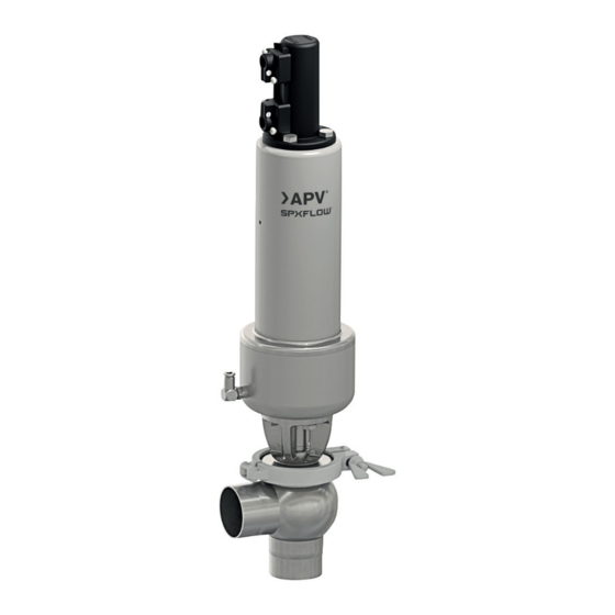
The valves are designed for universal applications and stand out for their increased mechanical reliability and absolute ease of service. The APV UF4/UFR4 valve is used to prevent a desired product pressure from being exceeded due to process requirements or to discharge a certain product quantity. -
Page 19: Auxiliary Equipment
UF4/UFR4 valves equipped with (Zone 1) IECEx CU ex ia Control Unit can be used for temperature classes T4 & T3. Please see table 4.2 Pressure Relief Valves APV UF4/UFR4 in Potentially Explosirve Areas Instruction Manual: GB - rev. 0... -
Page 20: Zone 2 Atex - Cu4 / Cu4Plus Control Unit & Adapter
CU S-adapter ATEX Zone 2 H333143 UF4/UFR4 valves equipped with CU4 or CU4plus ATEX Zone 2 can be used for temperature class T4. Please see table ontrol units 4.2. Pressure Relief Valves APV UF4/UFR4 in Potentially Explosirve Areas Instruction Manual: GB - rev. 0... -
Page 21: Seat Lift Actuator
Different housing shapes can be applied to reduce dead spaces to a minimum. air connection for seat lifting fig. 7.6. fig. 7.5. UF41 UFE41 UF42 regulating cone UFE42 UFE43 UFE44 Pressure Relief Valves APV UF4/UFR4 in Potentially Explosirve Areas Instruction Manual: GB - rev. 0... -
Page 22: Cleaning
It is, however, recommended to clean such surfaces with a damp cloth and with slow rubbing motion during the presence of hazardous atmospheres. Pressure Relief Valves APV UF4/UFR4 in Potentially Explosirve Areas Instruction Manual: GB - rev. 0... -
Page 23: Installation And Commissioning
If required, the value can be corrected during production by turning the adjusting screw at the actuator. Pressure Relief Valves APV UF4/UFR4 in Potentially Explosirve Areas Instruction Manual: GB - rev. 0... -
Page 24: Pressure Setting
8. Test the relief pressure by increasing the pressure in the system. The valve should open when the pressure reaches the set point. control unit Pressure Relief Valves APV UF4/UFR4 in Potentially Explosirve Areas Instruction Manual: GB - rev. 0... -
Page 25: Welding Instructions
If these welding instructions are not followed, any resulting damage will not be covered by the warranty. Welding directives for aseptic applications shall be drawn from the AWS/ANSI Directives and EHEDG Guidelines. Pressure Relief Valves APV UF4/UFR4 in Potentially Explosirve Areas Instruction Manual: GB - rev. 0... -
Page 26: Dimensions And Weights
34,9 2" 47,6 2,5" 60,3 3" 72,9 14,5 10,2 4" 97,6 17,1 *Min. response pressure is depending on the installation position and friction > 0, Pressure Relief Valves APV UF4/UFR4 in Potentially Explosirve Areas Instruction Manual: GB - rev. 0... - Page 27 11,8 3" 72,9 14,5 18,5 12,2 10,2 14,2 4" 97,6 17,1 21,1 *Min. response pressure is depending on the installation position and friction > 0 Pressure Relief Valves APV UF4/UFR4 in Potentially Explosirve Areas Instruction Manual: GB - rev. 0...
-
Page 28: Uf4/Ufr4 Valve With Cu4 / Cu4Plus Atex Control Unit (Zone 2)
2,5" 60,3 3" 72,9 14,5 15,5 10,2 11,2 4" 97,6 17,1 18,1 *Min. response pressure is depending on the installation position and friction > 0 Pressure Relief Valves APV UF4/UFR4 in Potentially Explosirve Areas Instruction Manual: GB - rev. 0... -
Page 29: Technical Data
Content of oil: quality class 1, max. 0,01 mg/m³ The oil applied must be compatible with Polyurethane elastomer materials. Pressure Relief Valves APV UF4/UFR4 in Potentially Explosirve Areas Instruction Manual: GB - rev. 0... -
Page 30: Kvs Values
0 - 0,6 0,2 - 1,2 1,0 - 3,5 3,0 - 10 DN100/4" 0 - 0,6 0,2 - 1,2 1,0 - 3,3 2,8 - 10 Pressure Relief Valves APV UF4/UFR4 in Potentially Explosirve Areas Instruction Manual: GB - rev. 0... -
Page 31: Maintenance
Do not use grease containing mineral oil for EPDM seals. Less suited grease types can influence function and service life. For valve assembly instructions, see section 13. Pressure Relief Valves APV UF4/UFR4 in Potentially Explosirve Areas Instruction Manual: GB - rev. 0... - Page 32 In case of damage, incomplete actuator movement, considerable running noise Change interval of actuator of spring as well as after 250,000 cycles* as preventive measure, however, after 10 years at the latest. *complies with about 8 years in 1-shift-operation and 10-15 cycles per hour. Pressure Relief Valves APV UF4/UFR4 in Potentially Explosirve Areas Instruction Manual: GB - rev. 0...
-
Page 33: Service Instructions
Detach clamp (6) and lift valve insert off the housing (1). Shut off compressed air and remove compressed air supply. Remove control unit (24) or PSH proximity switch holder (21) from actuator. Pressure Relief Valves APV UF4/UFR4 in Potentially Explosirve Areas Instruction Manual: GB - rev. 0... -
Page 34: Dismantling Of Wear Parts (Product-Wetted Parts)
The actuator can be maintained. See chapter 14. Service Instructions for Actuator. Detach the seat seal (7), shaft seal (8) and guide bushing (9). Remove housing seal (5). Pressure Relief Valves APV UF4/UFR4 in Potentially Explosirve Areas Instruction Manual: GB - rev. 0... -
Page 35: Installation Of Seals And Assembly Of Valve
Fasten the operating cam on the guide rod. regulating cone (4.1) Place the control unit (pos. 24) on the adapter. Pressure Relief Valves APV UF4/UFR4 in Potentially Explosirve Areas Instruction Manual: GB - rev. 0... -
Page 36: Installation Of Valve
- actuator 12. Place the actuator in the closed limit position and carry out positioning of the second proximity switch. hex. screw M8 Pressure Relief Valves APV UF4/UFR4 in Potentially Explosirve Areas Instruction Manual: GB - rev. 0... -
Page 37: Service Instructions For Actuator
Note! The connecting rod must move smoothly without friction in (12.3) the bushing. 5. Fasten the air hose. detail seal screw: O-ring (12.5) V-seal (12.4) Pressure Relief Valves APV UF4/UFR4 in Potentially Explosirve Areas Instruction Manual: GB - rev. 0... -
Page 38: Assembly Tool For Seat Seal
000 51-13-111/17 H179466 2" 000 51-13-112/17 H179467 2,5" 000 51-13-120/17 H179468 000 51-13-113/17 H179469 3" 000 51-13-121/17 H179470 000 51-13-114/17 H179471 4" 000 51-13-115/17 H179472 Pressure Relief Valves APV UF4/UFR4 in Potentially Explosirve Areas Instruction Manual: GB - rev. 0... -
Page 39: Trouble Shooting
Do not open cylinder by force. Spring force! Valve position indication No feedback. Carry out fine adjustment. Additional reference is given to the Instruction Manuals of the Control Units: APV IECEx CU ex ia (ATEX Zone 1 Gas Applications) CU4 for ATEX Zone 2 Gas Applications CU4plus ATEX Zone 2 Gas Applications with different inner designs. Pressure Relief Valves APV UF4/UFR4 in Potentially Explosirve Areas Instruction Manual: GB - rev. 0... -
Page 40: Spare Parts Lists
Please indicate the following data to place an order for spare parts: - number of required parts - reference number - designation Data are subject to change. Pressure Relief Valves APV UF4/UFR4 in Potentially Explosirve Areas Instruction Manual: GB - rev. 0... - Page 94 Design features, materials of construction and dimensional data, as described in this manual, are provided for your information only should not be relied upon unless confirmed in writing. Please contact your local sales representative for product availability in your region. For more information visit www.spxflow.com. ISSUED 07/2023 - Original Manual...
Need help?
Do you have a question about the APV UF4 and is the answer not in the manual?
Questions and answers