Table of Contents
Advertisement
Quick Links
I N S T R U C T I O N M A N U A L
APV CU4** AS-interface Control Unit
S A F E T Y A G A I N S T E X P L O S I O N - F O R I E C E x Z O N E 2 G A S A P P L I C AT I O N S
F O R M N O . : H 3 4 5 3 1 7
R E V I S I O N : G B - 1
R E A D A N D U N D E R S TA N D T H I S M A N U A L P R I O R TO O P E R AT I N G O R S E RV I C I N G T H I S P R O D U C T.
Advertisement
Table of Contents

Related Manuals for SPXFLOW APV CU4 Series


Summary of Contents for SPXFLOW APV CU4 Series
- Page 1 I N S T R U C T I O N M A N U A L APV CU4** AS-interface Control Unit S A F E T Y A G A I N S T E X P L O S I O N - F O R I E C E x Z O N E 2 G A S A P P L I C AT I O N S F O R M N O .
- Page 3 DocuSign Envelope ID: 3772203F-DF63-45FE-A28F-5CDF8FFEE948 CE Declaration of Conformity UKCA Declaration of Conformity DESIGN CENTER/MANUFACTURER: SPX Flow Technology Germany GmbH Gottlieb-Daimler-Str. 13, D-59439 Holzwickede MANUFACTURING FACILITY: SPX Flow Technology Poland sp. z o.o. Rolbieskiego 2, 85-862 Bydgoszcz, Poland AUTHORIZED REPRESENTATIVE: SPX Flow Europe Ltd. (for UKCA) Part Ground floor, Alexander House 4 Station Road Cheadle Hulme...
-
Page 5: Table Of Contents
SPX FLOW SPX FLOW_CU4.. AS-interface_IECEx_Zone 2_GB-1_062023_for D4. Valves.indd Content Page IECEx Specific Instructions 0.1. General Information 0.2. IECEx Specific Symbol 0.3. Authorized Use 0.4. Specific Safety Instructions 0.5. Identification of CU4** resp. CU4*plus* Control Units for use in IECEx ATEX environment 0.6. Responsibilities Abbreviations and Definitions Safety Instructions... -
Page 6: General Information
SPX FLOW SPX FLOW_CU4.. AS-interface_IECEx_Zone 2_GB-1_062023_for D4. Valves.indd IECEx Specific Instructions 0.1. General Information These IECEx Specific Safety Instructions apply for CU4** resp. CU4*plus* Control Units used in Potentially Explosive Atmospheres Zone 2, Gas applications. The equipment was assessed according to IEC 60079-0:2017, Edition 7.0 and IEC 60079-7:2017, Edition 5.1. Notified body: TÜV NORD CERT GmbH, Hanover-Office Am TÜV 1, 30519 Hanover, Germany Notified Body number: 0044... -
Page 7: Specific Safety Instructions
SPX FLOW SPX FLOW_CU4.. AS-interface_IECEx_Zone 2_GB-1_062023_for D4. Valves.indd IECEx Specific Instructions 0.4. Specific Safety Instructions Connecting/Disconnecting pluggable electric circuits The connecting and disconnecting of the pluggable electrical circuits including field wirings is only permitted in the absence of explosive atmosphere. lead seal Opening the device Do not open the control unit in the presence of explosive atmosphere. - Page 8 SPX FLOW SPX FLOW_CU4.. AS-interface_IECEx_Zone 2_GB-1_062023_for D4. Valves.indd IECEx Specific Instructions 0.4. Specific Safety Instructions In order to prevent the emergence of explosion risks observe the safety instructions of the instruction manual and adhere to the following: The required degree of protection (IP64) is guaranteed only in connection with suitable adaption sets. All pneumatic and electrical connections must be equipped with suitable connectors. Install the control unit in such a way that it is protected from UV- radiation.
-
Page 9: Identification Of Cu4** Resp. Cu4*Plus* Control Units For Use In Iecex Atex Environment
SPX FLOW SPX FLOW_CU4.. AS-interface_IECEx_Zone 2_GB-1_062023_for D4. Valves.indd IECEx Specific Instructions 0.5. Identification of CU4** resp. CU4*plus* Control Units for use in IECEx ATEX environment IECEx / ATEX - identification: Equipment group II Explosion subcategory Ex ec IIB T4 Gc Ambient temperature 0 °C ≤ T ≤ +55 °C 0.6. Responsibilities It is within the operator`s responsibility to ensure that the specified product temperatures are not exceeded and that regular inspections and maintenance are carried out to provide for proper function of the control unit and valve. -
Page 10: Abbreviations And Definitions
SPX FLOW SPX FLOW_CU4.. AS-interface_IECEx_Zone 2_GB-1_062023_for D4. Valves.indd Abbreviations and Definitions Exhaust Air AWG American Wire Gauge CE Communauté Européenne CU Control Unit DI Digital Input DO Digital Output EMC Electromagnetic Compatibility EU European Union GND Ground IP International Protection LED Luminous Diode Pneumatic Air Connection NOT element NEMA National Electrical Manufacturers Association Supply Air Connection PWM Pulse-Width Modulation Pneumatic Air Connection Safety Instructions 2.1. Sentinels Meaning: Danger! Direct danager which can lead to severe boldily... -
Page 11: Intended Use
SPX FLOW SPX FLOW_CU4.. AS-interface_IECEx_Zone 2_GB-1_062023_for D4. Valves.indd Safety Instructions 2.2. Intended Use The CU4 control unit is only intended for use as described in chapter 3.1. Use beyond that described in chapter 3.1. is not according to the regulations and SPX FLOW shall not be held responsible for any damage resulting from this non-observance. -
Page 12: Welding Instructions
SPX FLOW SPX FLOW_CU4.. AS-interface_IECEx_Zone 2_GB-1_062023_for D4. Valves.indd Safety Instructions 2.4. Welding instructions It is generally recommended to avoid welding work in process installations in which control units are installed and connected. If welding is nonetheless required, earthing of the electrical devices in the welding area is a necessity. 2.5. -
Page 13: General Terms
SPX FLOW SPX FLOW_CU4.. AS-interface_IECEx_Zone 2_GB-1_062023_for D4. Valves.indd General Terms 3.1. Purpose of use The CU4 AS-interface Control Unit was developed for the control of process valves used in the food and related industries. The CU4 control unit operates as interface between process control fig. - Page 14 SPX FLOW SPX FLOW_CU4.. AS-interface_IECEx_Zone 2_GB-1_062023_for D4. Valves.indd General Terms 3.3. Function of the individual components The installation of the control unit is undertaken by special adapters which are available for the different valves types, see chapter 5. Adapter. The snap connectors for supply air and pneumatic air to the individual cylinders at the valves are located at the outside of the control unit.
-
Page 15: Function Of The Individual Components
SPX FLOW SPX FLOW_CU4.. AS-interface_IECEx_Zone 2_GB-1_062023_for D4. Valves.indd General Terms 3.3. Function of the individual components The luminous diodes are located on the front side of the electronic module. Their signals are visibly indicated to the outside by an optical window in the cover of the control unit. Beside the open and closed valve position, the existence of the operating voltage as well as different diagnostic information are indicated. - Page 16 SPX FLOW SPX FLOW_CU4.. AS-interface_IECEx_Zone 2_GB-1_062023_for D4. Valves.indd Mechanics and Pneumatics 4.1. Air connections for double seat mix proof valves 4.1.1. Function CU41-D4 design for double seat mix proof valves without seat lift P ir supply with integrated particle filter Y1 control air connection for main actuator A1 exhaust air with silencer AIR IN CU43-D4 design for double seat mixproof valves with seat lift P air supply with integrated particle filter Y1 pneumatic air connection for main actuator Y2 pneumatic air connection for seat lift actuator of upper seat lift Y1 Y2 (N) Y3...
- Page 17 SPX FLOW SPX FLOW_CU4.. AS-interface_IECEx_Zone 2_GB-1_062023_for D4. Valves.indd Mechanics and Pneumatics 4.3. Functional description - block diagrams 4.3.1. CU41-D4 AS-interface for D4 double seat mix proof valve without seat lift function AS-i-Bus + AS-i-Bus - The picture shows a standard NC (spring to closed) valve. 5 VDC Sensor 1 5 VDC Sensor 2 Normal Feedback Reverse M1 - magnet upper shaft M2 - magnet lower shaft Sensor 2 “Valve open”...
- Page 18 SPX FLOW SPX FLOW_CU4.. AS-interface_IECEx_Zone 2_GB-1_062023_for D4. Valves.indd Mechanics and Pneumatics 4.3. Functional description - block diagrams 4.3.2 CU43-D4 AS-interface for D4 SL double seat mix proof valves with seat lift function AS-i-Bus + AS-i-Bus - 5 VDC The picture shows a standard NC Sensor 1 (spring to closed) valve. 5 VDC Sensor 2 Normal Feedback Reverse M1 - magnet upper shaft M2 - magnet lower shaft Sensor 3 “Valve closed”...
- Page 19 SPX FLOW SPX FLOW_CU4.. AS-interface_IECEx_Zone 2_GB-1_062023_for D4. Valves.indd Mechanics and Pneumatics 4.4. Technical Data / Standards Material: PA6.6 Ambient temperature: 0°C to +55°C (limitation due to ATEX application) EMC 2014/30/EU (89/336/EEC) Standards and environmental audits: Protection class IP 67 EN60529/ EMC interference resistance EN61000-6-2 EMC emitted interference EN61000-6-4 Vibration/oscillation EN60068-2-6 Safety of machinery DIN EN ISO 13849-1...
-
Page 20: Mechanics And Pneumatics
SPX FLOW SPX FLOW_CU4.. AS-interface_IECEx_Zone 2_GB-1_062023_for D4. Valves.indd Mechanics and Pneumatics 4.5. Solenoid valves In the base of the control unit max. 3 solenoid valves are installed. The 3/2-way solenoid valves are connected with the electronic module by moulded cables and plug connectors. Control: effected by pwm-signal Lever:... -
Page 21: Adapter
SPX FLOW SPX FLOW_CU4.. AS-interface_IECEx_Zone 2_GB-1_062023_for D4. Valves.indd Adapter Adapter for Double seat mix proof valves D4, D4 SL Control Unit CU4** AS-interface IECEx Zone 2 Gas for D4* Valves IECEx Zone 2 Gas Instruction manual: GB - rev. 1... - Page 22 SPX FLOW SPX FLOW_CU4.. AS-interface_IECEx_Zone 2_GB-1_062023_for D4. Valves.indd Electronic module 6.1. Function / Block diagram The Control Unit CU4 AS-interface is a slave for the fieldbus system AS-interface. It complies with the specification V3.0. The profile is S-7.A.*.E (3 outputs and 2 inputs). By means of a connecting terminal, the inputs can either be connected with internal APV Hall effect sensors or with external inductive proximity switches (compare 6.5.).
- Page 23 SPX FLOW SPX FLOW_CU4.. AS-interface_IECEx_Zone 2_GB-1_062023_for D4. Valves.indd Electronic module 6.1.2 Switch-over of feedback signals The signals to the control can be switched over via the bridge between the terminals 10, 11 and 12. If a bridge is located between the terminals 10 and 11 (normal), the signal is transferred from sensor 1 (closed valve position) to input DI0 of the control.
-
Page 24: Electronic Module
SPX FLOW SPX FLOW_CU4.. AS-interface_IECEx_Zone 2_GB-1_062023_for D4. Valves.indd Electronic module 6.3. Use of data bits Communication data The use of the data bits shall be drawn from the following table: Data bit Info Connection Level main valve Low (no electric current) (output) High (current) upper seat lifting (optional) Low (no electric current) (output) High (current) lower seat lifting (optional) Low (no electric current) output) High (current) -
Page 25: Technical Data
SPX FLOW SPX FLOW_CU4.. AS-interface_IECEx_Zone 2_GB-1_062023_for D4. Valves.indd Electronic module 6.4. Technical Data AS-interface profile: S-7.A.*.E (S-7.F.F.F as option) Extended address range: is supported Serial communication mode: Inverse polarity protection: exists Indication "Power": LED3 (green) Indication "Fault": LED3 (red) AS-interface voltage range: 26,5…31,6 V Max. power input: <= 150 mA Input delay time: < 1 s AS-interface specification: V3.0 Supply of solenoid valves: PWM signal from... -
Page 26: Connections
SPX FLOW SPX FLOW_CU4.. AS-interface_IECEx_Zone 2_GB-1_062023_for D4. Valves.indd Electronic module 6.5. Connections Sensors to detect the valve positions: Internal sensors: Hall effect sensors, APV D4 valves: H337014 UB 4,75-5,25 VDC operating distance according to SPX FLOW specification Control Unit CU4** AS-interface IECEx Zone 2 Gas for D4* Valves IECEx Zone 2 Gas Instruction manual: GB - rev. -
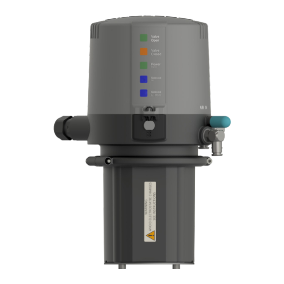
Page 27: Led Indication
SPX FLOW SPX FLOW_CU4.. AS-interface_IECEx_Zone 2_GB-1_062023_for D4. Valves.indd Electronic module 6.6. LED indication External luminous displays Valve Open colour: green, permanent light Valve in open position Valve Closed colour: orange, permanent light Valve in closed position Valve Open colour: green, flashing Bridge missing at terminals 10, 11, 12 Valve Closed colour: orange, flashing... -
Page 28: Feedback Unit
SPX FLOW SPX FLOW_CU4.. AS-interface_IECEx_Zone 2_GB-1_062023_for D4. Valves.indd Feedback unit 7.1. General terms For the internal registration of the valve position indication, the feedback unit with 2 Hall effect sensors is applied. It is used when single seat and butterfly valves are installed. The control of these sensors is effected by magnets assembled on the valve shaft rod. -
Page 29: Cu Assembly And Startup
SPX FLOW SPX FLOW_CU4.. AS-interface_IECEx_Zone 2_GB-1_062023_for D4. Valves.indd CU Assembly and Startup 8.1. Double seat mix proof valves D4, D4 SL CU cover CU41/CU43 operating cam with magnet M1 screws clamp ring adapter operating cam with magnet M2 actuator Assembly of the control unit on the valve 1. Assemble the magnet M2 on the upper shaft under the stop screw. 2. - Page 30 SPX FLOW SPX FLOW_CU4.. AS-interface_IECEx_Zone 2_GB-1_062023_for D4. Valves.indd CU Assembly and Startup 8.1.1 Pneumatic connection Supply air: Caution! Shut off the compressed air supply before connecting the air hose! Make sure that the air hose is professionally cut to length. Use a hose cutter for this purpose. Pneumatic air to valve actuator: Connect pneumatic air connection Y1 with the valve actuator.
- Page 31 SPX FLOW SPX FLOW_CU4.. AS-interface_IECEx_Zone 2_GB-1_062023_for D4. Valves.indd CU Assembly and Startup 8.1.3 Connection of external proximity switches lever The electric connection of the proximity switches specified by SPX FLOW is undertaken according to the terminal layout described in chapter 6.1. The mechanic assembly of the proximity switches is carried out at the actuator of the corresponding double seat valves.
-
Page 32: Accessories And Tools
SPX FLOW SPX FLOW_CU4.. AS-interface_IECEx_Zone 2_GB-1_062023_for D4. Valves.indd Accessories and Tools Assembly/disassembly - adapter on valve actuator: • hexagon socket wrench 6 mm • screwdriver 4mm Assembly/disassembly – CU on adapter: • hexagon socket wrench 3 mm Assembly/disassembly – electronic module: • torx wrench TX20 • screwdriver 3.5 mm Assembly/disassembly – feedback unit: • torx wrench TX15 Assembly/disassembly – electronic modules: •... -
Page 33: Service
SPX FLOW SPX FLOW_CU4.. AS-interface_IECEx_Zone 2_GB-1_062023_for D4. Valves.indd 10. Service 10.1. Dismantling Before disassembly, verify the following items: Feedback unit for • The valve must be in safety position and must not be controlled! SPX FLOW APV D4 valves • Shut off air supply! •... -
Page 34: Trouble Shooting
SPX FLOW SPX FLOW_CU4.. AS-interface_IECEx_Zone 2_GB-1_062023_for D4. Valves.indd 11. Trouble Shooting General Failures Remedy Valve position is not indicated. Re-adjust Hall sensors. Check fastening of magnetic operating cam. Check cabeling of the Hall sensors to the electronic module. Feedback via proximity Check positioning of proximity switches is missing switches. - Page 35 SPX FLOW SPX FLOW_CU4.. AS-interface_IECEx_Zone 2_GB-1_062023_for D4. Valves.indd 11. Trouble Shooting Failure Remedy Control Unit CU43 installed on D4 SL Double seat valves Valve position movement is Check if the right control unit is missing with actuated solenoid installed. Check label in type valve. window of control unit: CU43-D4-AS-interface Check valve movement with lever at solenoid valve.
-
Page 36: Iecex / Ccc Certificate Of Conformity
SPX FLOW SPX FLOW_CU4.. AS-interface_IECEx_Zone 2_GB-1_062023_for D4. Valves.indd 12. IECEx / CCC Certificate of Conformity Please see attachment. 13. Spare Parts Lists The reference numbers of spare parts for the different control unit designs and adapters are included in the attached spare parts drawings with corresponding lists. When you place an order for spare parts, please indicate the following data: number of parts required... - Page 38 IECEx Certificate of Conformity INTERNATIONAL ELECTROTECHNICAL COMMISSION IEC Certification System for Explosive Atmospheres for rules and details of the IECEx Scheme visit www.iecex.com Certificate No.: IECEx TUN 22.0020X Page 1 of 3 Certificate history: Current Status: Issue No: 0 Date of Issue: 2023-09-11 Applicant: SPX Flow Technology Germany GmbH...
- Page 39 IECEx Certificate of Conformity Certificate No.: IECEx TUN 22.0020X Page 2 of 3 Date of issue: 2023-09-11 Issue No: 0 Manufacturer: SPX Flow Technology Germany GmbH Gottlieb-Daimler-Str. 13 59439 Holzwickede Germany SPX Flow Technology Germany SPX Flow Technology Poland Sp. z Manufacturing locations: GmbH...
- Page 40 IECEx Certificate of Conformity Certificate No.: IECEx TUN 22.0020X Page 3 of 3 Date of issue: 2023-09-11 Issue No: 0 EQUIPMENT: Equipment and systems covered by this Certificate are as follows: Description: The control unit type CU4** resp. CU4*plus* is provided for controlling process valves in hazardous areas, it used as an interface between the process control and the process valve and operates the electrical and pneumatic signals.
- Page 41 TÜV NORD CERT GmbH Hannover Office Am TÜV 1 30519 Hannover Germany Page 1 of 5 Attachment to IECEx TUN 22.0020X issue No.: 0 General product information: Description: The control unit type CU4** resp. CU4*plus* is provided for controlling process valves in hazardous areas, it used as an interface between the process control and the process valve and operates the electrical and pneumatic signals.
- Page 42 TÜV NORD CERT GmbH Hannover Office Am TÜV 1 30519 Hannover Germany Page 2 of 5 Attachment to IECEx TUN 22.0020X issue No.: 0 Electrical data: For the control unit type CU4* plus AS-interface Internal / External Terminal Designation Functional description External AS-i + Connection AS-i network (26.5 V…31.6 V d.c.)
- Page 43 TÜV NORD CERT GmbH Hannover Office Am TÜV 1 30519 Hannover Germany Page 3 of 5 Attachment to IECEx TUN 22.0020X issue No.: 0 For the control unit type CU4* plus 24V Direct Connect: Internal / External Terminal Designation Functional description External Power+ Power supply 24V d.c.
- Page 44 TÜV NORD CERT GmbH Hannover Office Am TÜV 1 30519 Hannover Germany Page 4 of 5 Attachment to IECEx TUN 22.0020X issue No.: 0 For the control unit type CU4*24V Direct Connect: Internal / External Terminal Designation Functional description External Power+ Power supply 24V d.c.
- Page 45 TÜV NORD CERT GmbH Hannover Office Am TÜV 1 30519 Hannover Germany Page 5 of 5 Attachment to IECEx TUN 22.0020X issue No.: 0 Thermal data: Control unit type CU4** resp. CU4*plus*: Permissible ambient temperature range during operation: 0 °C ≤ Ta ≤ +55 °C Double seat valve type D4*: The permissible ambient temperature range as process temperature (medium or cleaning solutions temperature) depending on the temperature class is shown in the following table:...
- Page 47 No.:2023312304001783 SPX(Shanghai) Flow Technology Company Limited Applicant No.666, Fengjin Road, Xidu Industry park, Fengxian District, Address Shanghai China SPX Flow Technology Poland Sp. z o.o. Manufacturer Stanisława Rolbieskiego 2, Bydgoszcz 85-862, Poland Address SPX Flow Technology Poland Sp. z o.o. Production Factory Stanisława Rolbieskiego 2, Bydgoszcz 85-862, Poland Production Address...
- Page 48 No.:2023312304001783 Page 1 of 8 Product information: This certificate covers the following models: - CU4** , CU4*plus* Nomenclature: 1) CU4** 1: 1 solenoid 2: 1 solenoid, 1NOT element 3: 3 solenoids AS-interface 24V Direct Connect 2) CU4*plus* plus 1: 1 solenoid 2: 1 solenoid, 1NOT element 3: 3 solenoids AS-interface...
- Page 49 No.:2023312304001783 Page 2 of 8 Control unit type CU4*AS-interface Internal / Terminal Designation Functional description External External AS-i + Connection AS-i network (26.5 V…31.6 V d.c.) External AS-i - Connection AS-i network (GND) Internal 5 VDC Voltage supply for proximity switches Internal Sensor 1 Signal sensor 1 (closed valve position)
- Page 50 No.:2023312304001783 Page 3 of 8 External SV Digital Output Common External DI0 Digital Input PLC output to activate solenoid 1 / main valve External DI1 Digital Input PLC output to activate solenoid 2 / upper seat lift External PLC output to activate solenoid 3 / lower DI2 Digital Input seat lift External...
- Page 51 No.:2023312304001783 Page 4 of 8 Internal Bridge Z+ / PELV E+ (in case of energy supply for solenoid valves via AS-i bus) Internal Bridge Z- / PELV E - (in case of energy supply for solenoid valves via AS-i bus) Internal PELV E+ Separate auxiliary energy PELV 24VDC + (for...
- Page 52 No.:2023312304001783 Page 5 of 8 Internal Solenoid valve 3 (lower seat lift) Internal Optional connection - pressure sensor External Service port Connection serial/USB converter for CU4plus toolbox software Control unit type CU4* plus 24V Direct Connect Internal / Terminal Designation Functional description External External...
- Page 53 No.:2023312304001783 Page 6 of 8 Internal Signal SPX prox. sensor Internal Potential for SPX prox. sensor / linear sensor Internal Linear sensor Internal PWM Output Solenoid valve 1 (main valve) Internal PWM Output Solenoid valve 2 (upper seat lift) Internal PWM Output Solenoid valve 3 (lower seat lift) External...
- Page 54 No.:2023312304001783 Page 7 of 8 Internal Sensor 1 Linear Sensor 1 Internal Sensor 2 Sensor Signal 2 Internal Mass potential for sensor supply Internal PWM Output Solenoid valve 1 (main valve) Internal PWM Output Solenoid valve 2 (upper seat lift) Internal PWM Output Solenoid valve 3 (lower seat lift)
- Page 55 No.:2023312304001783 Page 8 of 8 - Measures have to be taken, external to the control unit type CU4** resp. CU4*plus*, to provide a transient protection that ensures that the rated voltage, connected to the power supply terminals, is not exceeded by more than 40%. - See instruction for other information.
- Page 57 Information contained in this document is subject to change without notice and does not represent a commitment on the part of SPX FLOW, Inc.. No part of this document may be reproduced or transmitted in any form or by any means, electronic or mechanical, including photocopying and recording, for any purpose, without the express written permission of SPX FLOW, Inc..
- Page 58 Information contained in this document is subject to change without notice and does not represent a commitment on the part of SPX FLOW, Inc.. No part of this document may be reproduced or transmitted in any form or by any means, electronic or mechanical, including photocopying and recording, for any purpose, without the express written permission of SPX FLOW, Inc..
- Page 59 Weitergabe sowie Vervielfältigung dieser Unterlage, Verwertung und Mitteilung ihres Inhalts nicht gestattet, soweit nicht schriftlich zugestanden. Verstoß verpflichtet zum Schadensersatz und kann strafrechtliche Folgen haben (Paragraph 18 UWG, Paragraph 106 UrhG). Eigentum und alle Rechte, auch für Patenterteilung und Gebrauchsmustereintragung, vorbehalten. SPX FLOW, Germany Ersatzteilliste: spare parts list Datum: 11/08 01/09 03/09 11/10 Name: Peters Peters Trytko Schulz SPX FLOW Geprüft: Peters Spliethoff Spliethoff Spliethoff CU4 Adapter Datum: Blatt 03/13 11/14 05/18 Name: Trytko Trytko C.Keil RN 01.044.3 Geprüft: Schulz C.Keil...
- Page 60 Weitergabe sowie Vervielfältigung dieser Unterlage, Verwertung und Mitteilung ihres Inhalts nicht gestattet, soweit nicht schriftlich zugestanden. Verstoß verpflichtet zum Schadensersatz und kann strafrechtliche Folgen haben (Paragraph 18 UWG, Paragraph 106 UrhG). Eigentum und alle Rechte, auch für Patenterteilung und Gebrauchsmustereintragung, vorbehalten. SPX FLOW, Germany Ersatzteilliste: spare parts list Datum: 11/08 01/09 03/09 11/10 Name: Peters Peters Trytko Schulz SPX FLOW Geprüft: Peters Spliethoff Spliethoff Spliethoff CU4 Adapter Datum: Blatt 03/13 11/14 05/18 Name: Trytko Trytko C.Keil RN 01.044.3 Geprüft: Schulz C.Keil CU4 - S...
- Page 61 Weitergabe sowie Vervielfältigung dieser Unterlage, Verwertung und Mitteilung ihres Inhalts nicht gestattet, soweit nicht schriftlich zugestanden. Verstoß verpflichtet zum Schadensersatz und kann strafrechtliche Folgen haben (Paragraph 18 UWG, Paragraph 106 UrhG). Eigentum und alle Rechte, auch für Patenterteilung und Gebrauchsmustereintragung, vorbehalten. SPX FLOW, Germany Ersatzteilliste: spare parts list Datum: 11/08 01/09 03/09 11/10 Name: Peters Peters Trytko Schulz SPX FLOW Geprüft: Peters Spliethoff Spliethoff Spliethoff CU4 Adapter Datum: Blatt 03/13 11/14 05/18 Name: Trytko Trytko C.Keil RN 01.044.3 Geprüft: Schulz C.Keil CU4 - S...
- Page 62 Weitergabe sowie Vervielfältigung dieser Unterlage, Verwertung und Mitteilung ihres Inhalts nicht gestattet, soweit nicht schriftlich zugestanden. Verstoß verpflichtet zum Schadensersatz und kann strafrechtliche Folgen haben (Paragraph 18 UWG, Paragraph 106 UrhG). Eigentum und alle Rechte, auch für Patenterteilung und Gebrauchsmustereintragung, vorbehalten. SPX FLOW, Germany Ersatzteilliste: spare parts list Datum: 11/08 01/09 03/09 11/10 Name: Peters Peters Trytko Schulz SPX FLOW Geprüft: Peters Spliethoff Spliethoff Spliethoff CU4 Adapter Datum: Blatt 03/13 11/14 05/18 Name: Trytko Trytko C.Keil RN 01.044.3 Geprüft: Schulz C.Keil pos.
- Page 63 Weitergabe sowie Vervielfältigung dieser Unterlage, Verwertung und Mitteilung ihres Inhalts nicht gestattet, soweit nicht schriftlich zugestanden. Verstoß verpflichtet zum Schadensersatz und kann strafrechtliche Folgen haben (Paragraph 18 UWG, Paragraph 106 UrhG). Eigentum und alle Rechte, auch für Patenterteilung und Gebrauchsmustereintragung, vorbehalten. SPX FLOW, Germany Ersatzteilliste: spare parts list Datum: 11/08 01/09 03/09 11/10 Name: Peters Peters Trytko Schulz SPX FLOW Geprüft: Peters Spliethoff Spliethoff Spliethoff CU4 Adapter Datum: Blatt 03/13 11/14 05/18 Name: Trytko Trytko C.Keil RN 01.044.3 Geprüft: Schulz C.Keil pos.
- Page 64 Design features, materials of construction and dimensional data, as described in this manual, are provided for your information only and should not be relied upon unless confirmed in writing. Please contact your local sales representative for product availability in your region. For more information visit www.spxflow.com. ISSUED 06/2023 - Original Manual...
Need help?
Do you have a question about the APV CU4 Series and is the answer not in the manual?
Questions and answers