Table of Contents
Advertisement
Quick Links
Advertisement
Table of Contents

Related Manuals for SPXFLOW CU4plus Direct Connect


Summary of Contents for SPXFLOW CU4plus Direct Connect
- Page 1 I N S T R U C T I O N M A N U A L CU4plus Direct Connect C O N T R O L U N I T F O R M N O . : H 3 4 3 6 1 3 R E V I S I O N : G B - 1 R E A D A N D U N D E R S TA N D T H I S M A N U A L P R I O R TO O P E R AT I N G O R S E RV I C I N G T H I S P R O D U C T.
-
Page 5: Table Of Contents
Double seat mix proof valves D4, D4 SL, D4 PMO, DA4 8.5. Double seat tank outlet valve DT4 SL 8.6. Aseptic Double seat mix proof valve AM1 Accessories and Tools Service 10.1. Dismantling Trouble Shooting Spare Parts Lists Control Unit CU4plus Direct Connect Instruction Manual GB-1... -
Page 6: Abbreviations And Definitions
These special safety instructions point directly to the respective handling instructions. They are accentuated by the corresponding symbol. Carefully read the instructions to which the sentinels refer. Continue handling the control unit only after having read these instructions. Control Unit CU4plus Direct Connect Instruction Manual GB-1... -
Page 7: Intended Use
Safety Instructions 2.2. Intended use The CU4plus Direct Connect control unit is only intended for use as described in chapter 3.1. Use beyond that described in chapter 3.1. do not comply with the regulations and SPX FLOW shall not be responsible for any damage resulting from this non-observance. -
Page 8: Welding Instructions
Prerequisite for a guarantee is the correct use of the unit in compliance with the specified conditions of application. Note! This warranty only applies to the Control Unit. No liability will be accepted for consequential damage of any kind arising from failure or malfunction of the device. Control Unit CU4plus Direct Connect Instruction Manual GB-1... -
Page 9: General Terms
General Terms 3.1. Purpose of use fig. 3.2. The control unit CU4plus Direct Connect has been developed for the control of process valves in food processing industry as well as related industries. The CU4plus Direct Connect control unit operates as interface between process control and process valve and controls the electric and pneumatic signals. - Page 10 The corresponding signals of the linear sensor as well as external proximity switches are evaluated in an internal logic circuit and, thus, the corresponding valve position indications are generated. (see chapter 6.7. Data signals, PLC communication) Control Unit CU4plus Direct Connect Instruction Manual GB-1...
-
Page 11: Function Of The Individual Components
The complete control unit has been designed on the building block principle. By exchange of the electronic module, the control type can be changed, e.g. from direct control (Direct Connect) to communication with AS-Interface. Note! Wiring must be changed! Control Unit CU4plus Direct Connect Instruction Manual GB-1... -
Page 12: Mechanics And Pneumatics
Y1 pneumatic air connection for main actuator Y2 pneumatic air connection for seat lift actuator of upper seat lifting Y3 pneumatic air connection for seat lift actuator of lower seat lifting A1/A2 exhaust air with silencer Control Unit CU4plus Direct Connect Instruction Manual GB-1... - Page 13 A1/A2 exhaust air, with exhaust silencer AIR IN Control Unit CU4plus Direct Connect Instruction Manual GB-1...
-
Page 14: Pressure Relief Valve
If required, the pressure relief valve vents into the clearance between the base and the adapter of the control unit. The pressure relief valve must not be mechanically blocked under any circumstances. DANGER DANGER Control Unit CU4plus Direct Connect Instruction Manual GB-1... - Page 15 9 DI Upper Lift 10 DI Lower Lift 11 5VDC LED 2 12 Sensor 2 13 GND LED 1 JST Sensor 1 linear sensor solenoid valve throttle valves P / air supply A / exhaust Control Unit CU4plus Direct Connect Instruction Manual GB-1...
-
Page 16: Functional Description - Block Diagrams
LED 2 12 Sensor 2 13 GND LED 1 JST Sensor 1 linear sensor pressure reducing valve (locked to 5 bar) solenoid valve self-lock connector throttle valves P / air supply A / exhaust NOT element Control Unit CU4plus Direct Connect Instruction Manual GB-1... - Page 17 13 GND LED 1 JST Sensor 1 linear sensor (Y) A / exhaust P / air supply sol. valve 1 sensor 3 sol. valve 2 sensor 4 A / exhaust sol. valve 3 sensor 1 (Teach signal) sensor 2 (Teach signal) Control Unit CU4plus Direct Connect Instruction Manual GB-1...
- Page 18 (connected with sensor 2 M2 - magnet upper shaft e-module) linear sensor (in sensor tower, lower part) (connected with plug e-module) solenoid valve throttle valves P / air supply A / exhaust air Control Unit CU4plus Direct Connect Instruction Manual GB-1...
- Page 19 D4SL mix-proof valve is in the part) closed postion. (connected with sensor 2 e-module) linear sensor (in sensor tower, lower part) (connected with sensor 1 e-module) exhaust air sol. 1 sol. 2 exhaust air sol. 3 Control Unit CU4plus Direct Connect Instruction Manual GB-1...
- Page 20 DA4 mix-proof valve is in the part) closed postion. (connected with sensor 2 e-module) linear sensor (in sensor tower, lower part) (connected with sensor 1 e-module) exhaust air sol. 1 sol. 2 exhaust air sol. 3 Control Unit CU4plus Direct Connect Instruction Manual GB-1...
- Page 21 DT4 SL mix-proof valve is in the closed postion. external linear sensor exhaust air air supply sol. 1 sol. 2 exhaust air sol. 3 internal linear sensor Control Unit CU4plus Direct Connect Instruction Manual GB-1...
- Page 22 AM1 mix-proof valve is in the closed postion. internal linear sensor exhaust air air supply sol. 1 sol. 2 exhaust air sol. 3 external linear sensor Control Unit CU4plus Direct Connect Instruction Manual GB-1...
-
Page 23: Technical Data / Standards
1, max. 0,01 mg/m³ The oil applied must be compatible with Polyurethane elastomer materials. Control Unit CU4plus Direct Connect Instruction Manual GB-1... -
Page 24: Solenoid Valves
The air hose must be slided into the air connection until it stops in order to open the non-return valve. The NOT element is also used for air/air - actuators. Control Unit CU4plus Direct Connect Instruction Manual GB-1... -
Page 25: Adapter
5.1. Valves with turning actuator, e.g. butterfly valve 5.2. Single seat valve 5.3. Double seat mix proof valve DE3, DA3+ 5.4. Double seat mix proof valves D4, D4 SL, D4 PMO, DA4 Control Unit CU4plus Direct Connect Instruction Manual GB-1... -
Page 26: Double Seat Tank Outlet Valve Dt4 Sl
SPX FLOW_CU4plus_Direct Connect_GB-1_042024_CE_UKCA.indd Adapter Adapter for different process valves 5.5. Double seat tank outlet valve DT4 SL and AM1 aseptic mixproof valve 5.5.1. DT4 - 62 adapter 5.5.2. DT4 - 92 adapter Control Unit CU4plus Direct Connect Instruction Manual GB-1... -
Page 27: Electronic Module
Electronic Module 6.1. Function/block diagram The electronic module of the SPX FLOW CU4plus Direct Connect control unit is designed to be part of the PLC Input/Output system. It should be supplied with the same protected power supply as the other I/O devices. This power supply should not be used for other kinds of loads. - Page 28 3 9 DI Upper Lift LED 7 10 DI Lower Lift NI5-K11K-AN5X/5 11 5VDC LED 2 NI5-K11K-AN5X/5 12 Sensor 2 connection 13 GND sensor 4 for toolbox LED 1 JST Sensor 1 Control Unit CU4plus Direct Connect Instruction Manual GB-1...
- Page 29 LED 3/4 LED 8 Teach-in function 9 DI Upper Lift LED 7 10 DI Lower Lift 11 5VDC LED 2 12 Sensor 2 connection 13 GND for toolbox LED 1 JST Sensor 1 Control Unit CU4plus Direct Connect Instruction Manual GB-1...
- Page 30 Teach-in function 9 DI Upper Lift LED 7 10 DI Lower Lift Brown Black 11 5VDC LED 2 Blue 12 Sensor 2 13 GND connection for toolbox LED 1 JST Sensor 1 Control Unit CU4plus Direct Connect Instruction Manual GB-1...
-
Page 31: Functional Description Of Connections
SPX prox. sensor potential for SPX prox. sensor / linear sensor linear sensor PWM Output solenoid valve 1 (main valve) PWM Output solenoid valve 2 (upper seat lift) Electronic Module PWM Output solenoid valve 3 (lower seat lift) service port connection serial/USB converter for CU4plus toolbox Control Unit CU4plus Direct Connect Instruction Manual GB-1... -
Page 32: Technical Data
5 VDC, 4,75…5,25V (sum of all currents < 40mA) Caution! The sensor inputs and the peripheral supply must not be connected with installation- GND. Connecting terminals: conductor cross section 0.5 – 1,0 mm² (with conductor sleeve) complying with AWG 20-17 (max. 11 mm) Control Unit CU4plus Direct Connect Instruction Manual GB-1... -
Page 33: Connections
DO Valve closed DO Valve open DO upper lift DO Lower lift DO Service DI Main Valve DI Upper lift DI Lower lift DI M 5V DC Sensor 2 Sensor 1 DO M Control Unit CU4plus Direct Connect Instruction Manual GB-1... -
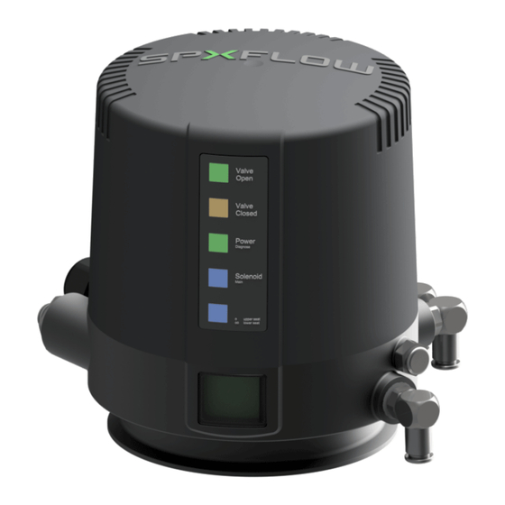
Page 34: 6.5. Led Indication / Indicator Lights
Teach-in required LED Y1 solenoid valve 1 permanent light controlled LED Y2 solenoid valve 1 permanent light controlled LED Y3 solenoid valve 1 permanent light controlled * Depending on the adjusted mode! Control Unit CU4plus Direct Connect Instruction Manual GB-1... -
Page 35: Adjustement Of Valve Profiles
(see chapter 7.2) Valve position indication: LED can be inverted, e.g. for adaption of valve type Delivery status: Mix proof valve DA4 profile is adjusted. Adjusted valve characteristics: logic profile 1, for DA3+ with SLD Teach-in: CU waits for Teach-in with valve, LED 3-6 blink Adjustment / change of valve profile is realized via ToolBox software (see Toolbox manual). Control Unit CU4plus Direct Connect Instruction Manual GB-1... - Page 36 1 sensor 2 Output signals signal generated by Teach-in signal generated by Teach-in (position of position sensor) (position of position sensor) closed open not occupied not occupied solenoid 1 Main solenoid 2 solenoid 3 Input signals Control Unit CU4plus Direct Connect Instruction Manual GB-1...
- Page 37 4 sensor signals. The appropriate valve position is shown direct by the output signals. Further ajdustments are not required! solenoid 1 solenoid 2 solenoid 3 main upper seat lower seat Input signals lift lift When replacing a CU3 control unit, use the following profile: CU3 compatible mode Double seat mix proof valve with seat lift detection (SLD) (all signals similar to CU3) - see instruction manual of CU3 Control Unit. Control Unit CU4plus Direct Connect Instruction Manual GB-1...
- Page 38 S3 closed not used +1 mm, -1 mm open +1 mm, not used -1 mm Input signal solenoid 1 solenoid 1 solenoid 1 Main upper seat lift lower seat lift Control Unit CU4plus Direct Connect Instruction Manual GB-1...
- Page 39 +1 mm, -1 mm upper seat lift +1 mm, -1 mm lower seat lift +1 mm, -1 mm Input signal solenoid 1 solenoid 2 solenoid 3 Main upper seat lift lower seat lift Control Unit CU4plus Direct Connect Instruction Manual GB-1...
- Page 40 - the opposite valve shaft stays in closed position, this can be monitored by watching the appropriate signal Digital Input solenoid 1 solenoid 2 solenoid 3 data Main upper seat lift lower seat lift Control Unit CU4plus Direct Connect Instruction Manual GB-1...
- Page 41 +1 mm, -1 mm upper seat lift +1 mm, -1 mm lower seat lift +1 mm, -1 mm Input signals solenoid 1 solenoid 2 solenoid 3 Main upper seat lift lower seat lift Control Unit CU4plus Direct Connect Instruction Manual GB-1...
- Page 42 +1 mm, -1 mm upper seat lift +1 mm, -1 mm lower seat lift +1 mm, -1 mm Output solenoid 1 solenoid 1 solenoid 1 signals Main upper seat lift lower seat lift Control Unit CU4plus Direct Connect Instruction Manual GB-1...
- Page 43 S2 lift Tolerance band closed fixed open +/- 1mm upper seat lift fixed lower seat lift fixed output solenoid 1 solenoid 2 solenoid 3 signals Main upper seat lift lower seat lift Control Unit CU4plus Direct Connect Instruction Manual GB-1...
- Page 44 +/- 1mm open +/- 1mm upper seat lift +/- 1mm lower seat lift +/- 1mm output solenoid 1 solenoid 2 solenoid 3 signals Main upper seat lift lower seat lift Control Unit CU4plus Direct Connect Instruction Manual GB-1...
-
Page 45: Data Signals
Windows 8.1, Windows 10. After installation of the CU4plus Toolbox the corresponding control unit is connected with the PC by means of an adapter cable. The individual functions are described in the CU4plus Toolbox manual. Control Unit CU4plus Direct Connect Instruction Manual GB-1... -
Page 46: Seat Pulsation - Efficiency In Cleaning
For the stroke based pulsation, default parameters are set. These can be adjusted within the CU4plus Toolbox. During pulsation, the feedback for the appropriate seat lift will always be active! Control Unit CU4plus Direct Connect Instruction Manual GB-1... -
Page 47: Valve Position Indication
D4 PMO, DA4, DT4 SL +/- 3 mm e.g. SW4, MS4 +/- 5 mm e.g. SV, SVS, DKR A fixed tolerance band is used for AM1 Valve tolerance tolerance tolerance valve band band band stroke (mm) ± 1mm ± 3mm ± 5mm Control Unit CU4plus Direct Connect Instruction Manual GB-1... -
Page 48: Adjustment Of Valve Position Indication / Teach-In
Teach-in not successful, repetition required. Possible reasons for Teach-in failure: Start Teach-in / press LED 9 blink Teach-in key for 3 sec. Compressed air is missing. Supply voltage missing. Switching logic does not fit to valve. Control Unit CU4plus Direct Connect Instruction Manual GB-1... -
Page 49: Use Of External Sensors
Note! Caution! The switching cam is not identical with the standard CU switching cam! CU4plus Direct Connect control unit is not duly installed on the valve. Valve is duly installed in the process. Valve is not manually controlled or controlled by PLC. -
Page 50: Cu Assembly And Startup
Secure with Loctite semi-solid and fasten it. 3. Place the control unit via the operating cam onto the adapter. Observe alignment. 4. Attach the clamp rings and fasten them with the screws. Control Unit CU4plus Direct Connect Instruction Manual GB-1... - Page 51 1. Switch on the air supply. 2. Switch on the voltage supply. 3. Adjust corresponding logic profile in accordance with the process valve used (if this has not been determined for the delivery status). Start Teach-in. It is mandatory to observe the corresponding prerequisites (see chapter 7.3.). Control Unit CU4plus Direct Connect Instruction Manual GB-1...
-
Page 52: Single Seat Valve
2. Secure switching cam with Loctite semi-solid and fasten it. 3. Place the control unit via the switching cam onto the adapter. Observe alignment! 4. Attach the clamp rings and fasten them with the screws. Control Unit CU4plus Direct Connect Instruction Manual GB-1... - Page 53 1. Switch on the air supply. 2. Switch on the voltage supply. 3. Adjust corresponding logic profile in accordance with the process valve used (if this has not been determined for the delivery status). 4. Start Teach-in. It is mandatory to observe the corresponding prerequisites (see chapter 7.3.). Control Unit CU4plus Direct Connect Instruction Manual GB-1...
-
Page 54: Double Seat Valve Da3+ With Activated Seat Lift Detection (Sld)
2. Align air connections of the control unit to the valve actuator. 3. Place the control unit onto the adapter. Observe alignment! 4. Attach the clamp rings and fasten them with the screws. 5. Assemble the external proximity switches at the actuator. Control Unit CU4plus Direct Connect Instruction Manual GB-1... - Page 55 6. The mechanic assembly of the proximity switches is carried out at the actuator of the corresponding double seat valves. Observance of the instruction manual for double seat valves is essential! Control Unit CU4plus Direct Connect Instruction Manual GB-1...
- Page 56 1. Switch on the air supply. 2. Switch on the voltage supply. 3. Adjust corresponding logic profile in accordance with the process valve used (if this has not been determined for the delivery status). 4. Start Teach-in. It is mandatory to observe the corresponding prerequisites (see chapter 7.3.). Control Unit CU4plus Direct Connect Instruction Manual GB-1...
-
Page 57: Double Seat Mix Proof Valves D4, D4 Sl, D4 Pmo, Da4
4. Place the control unit onto the adapter. Observe alignment! 5. Attach the clamp rings and fasten them with the 2 screws. 6. Align air connections of the control unit to the valve actuator. Control Unit CU4plus Direct Connect Instruction Manual GB-1... - Page 58 8.4.2 Electric connection Attention! Electric connections shall only be carried out by qualified personnel. Observe the Safety Instructions specified in chapter 2. Control Unit CU4plus Direct Connect Instruction Manual GB-1...
- Page 59 1. Switch on the air supply 2. Switch on the voltage supply. 3. Check the solenoid valves by turning the lever on the upper side by 90°. solenoid valve 4. For final adjustments of the feedback position switches please use the Teach function. Control Unit CU4plus Direct Connect Instruction Manual GB-1...
-
Page 60: Double Seat Tank Outlet Valve Dt4 Sl
5. Place the control unit onto the adapter. Observe alignment! 6. Attach the clamp rings and fasten them with the 2 screws. 7. Align air connections of the control unit to the valve actuator. Control Unit CU4plus Direct Connect Instruction Manual GB-1... - Page 61 8.5.2 Electric connection Attention! Electric connections shall only be carried out by qualified personnel. Observe the Safety Instructions specified in chapter 2. Control Unit CU4plus Direct Connect Instruction Manual GB-1...
-
Page 62: Aseptic Double Seat Mix Proof Valve Am1
5. Place the control unit onto the adapter. Observe alignment! 6. Attach the clamp rings and fasten them with the 2 screws. 7. Align air connections of the control unit to the valve actuator. Control Unit CU4plus Direct Connect Instruction Manual GB-1... - Page 63 8.6.2 Electric connection Attention! Electric connections shall only be carried out by qualified personnel. Observe the Safety Instructions specified in chapter 2. Control Unit CU4plus Direct Connect Instruction Manual GB-1...
-
Page 64: Accessories And Tools
Assembly/disassembly – electronic modules: • Torx wrench TX20 Assembly/disassembly – air connections: • jaw wrench SW13 Assembly/disassembly – pressure relief valve: • Torx wrench TX10 Loctite semi-solid jaw wrench torx wrench hexagon socket wrench screwdriver Control Unit CU4plus Direct Connect Instruction Manual GB-1... -
Page 65: 10. Service
The linear sensor can only be replaced at the dismantled feedback unit. + Remove the 2 screws (14) TX10. Release the plug connection at the electronic module. Dismantle the linear sensor. Assembly in reverse order. Carry out Teach-in. Control Unit CU4plus Direct Connect Instruction Manual GB-1... -
Page 66: Trouble Shooting
Check cabeling between electronic module and solenoid valve. Check compressed air (min. 6 bar). Bore for transfer of control air to turning actuator must be open. Air leakage at lower side of Check O-rings of adapter. adapter. Control Unit CU4plus Direct Connect Instruction Manual GB-1... - Page 67 Check cabeling between electronic module and solenoid valve. Check compressed air (min. 6 bar). Check control air connection between the CU43plus and the DA3 / DA4 / D4 SL / D4 PMO / DT4 SL / AM1 actuator. Control Unit CU4plus Direct Connect Instruction Manual GB-1...
-
Page 68: 12. Spare Parts Lists
When you place an order for spare parts, please indicate the following data: number of parts required ID number reference number parts designation Data are subject to change. Control Unit CU4plus Direct Connect Instruction Manual GB-1... -
Page 88: Control Unit
Design features, materials of construction and dimensional data, as described in this manual, are provided for your information only and should not be relied upon unless confirmed in writing. Please contact your local sales representative for product availability in your region. For more information visit www.spxflow.com. ISSUED 04/2024 - Original Manual...
Need help?
Do you have a question about the CU4plus Direct Connect and is the answer not in the manual?
Questions and answers