Advertisement
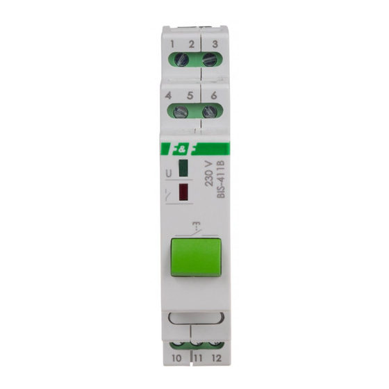
BIS-411B
Bistable relay
Do not dispose of this device in the trash along with other waste! According to the Law on
Waste, electro coming from households free of charge and can give any amount to up to
that end point of collec� on, as well as to store the occasion of the purchase of new equip-
ment (in accordance with the principle of old-for-new, regardless of brand). Electro thrown
in the trash or abandoned in nature, pose a threat to the environment and human health.
Purpose
Electronic bistable pulse relay BIS-411B allows switching on or off
the lighting or other device from several different points by paral-
lel connected, momentary (bell) control switches.
A push button on the housing enables direct control of the cir-
cuit without the need to trigger external buttons.
Functioning
The receiver is switched on after a current pulse caused by pres-
sing any momentary (bell) button connected to the relay. After
the next pulse, the receiver will be switched off. The relay does
not have a "memory" of the contact position, which means in
the event of a power failure and its subsequent return, the relay
contact will be set to "off". This prevents the controlled receivers
from being switched on automatically without supervision after
a prolonged power failure. The button on the housing performs
exactly the same function as the external button connected to
the terminals of the device.
F&F Filipowski sp. j.
Konstantynowska 79/81, 95-200 Pabianice, POLAND
phone/fax (+48 42) 215 23 83 / (+48 42) 227 09 71
www.fif.com.pl; e-mail: biuro@fif.com.pl
- 1 -
Advertisement
Table of Contents

Subscribe to Our Youtube Channel
Related Manuals for F&F BIS-411B


Summary of Contents for F&F BIS-411B
- Page 1 Purpose Electronic bistable pulse relay BIS-411B allows switching on or off the lighting or other device from several different points by paral- lel connected, momentary (bell) control switches.
- Page 2 6 and to the wire to which terminal 3 is connected. 5. Connect the powered receiver in series to terminals 11-12. The maximum total backlight current of all connected buttons must not exceed 5 mA. BIS-411B can work with backlit buttons. - 2 -...
- Page 3 Wiring diagram - 3 -...
- Page 4 power supply of the relay 165÷265 V AC control input NC contact (passive) relay common contact (COM) NO contact (active) - 4 -...
- Page 5 Technical data power supply 165÷265 V AC contact separated 1×NO/NC maximum load current (AC-1) 16 A control pulse current 5 mA activation delay 0.1÷0.2 s power supply indication green LED activation indication red LED mechanical life of the button 10⁶ cycles power consumption stand-by 0.15 W...
- Page 6 Power table tungsten halogen fluorescent energy-saving 2000 W 1250 W 1000 W 500 W 250 W The above data are indicative and will heavily depend on the design of a specific receiver (that is especially important for LED bulbs, energy-saving lamps, electronic transformers and pulse power supply units), switching frequency and operating conditions.
Need help?
Do you have a question about the BIS-411B and is the answer not in the manual?
Questions and answers