Table of Contents
Advertisement
Quick Links
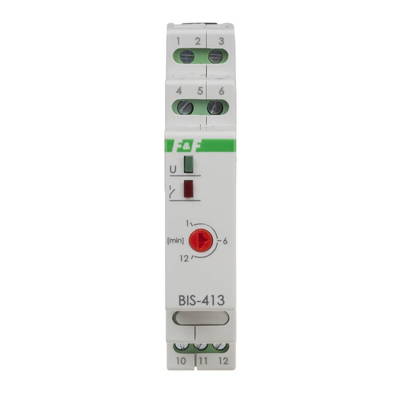
BIS-413M
Bistable relay with timing
switch and „memory"
contact position
Do not dispose of this device in the trash along with other waste! According to the Law on
Waste, electro coming from households free of charge and can give any amount to up to
that end point of collec� on, as well as to store the occasion of the purchase of new equip-
ment (in accordance with the principle of old-for-new, regardless of brand). Electro thrown
in the trash or abandoned in nature, pose a threat to the environment and human health.
Purpose
Electronic bistable pulse relay BIS-413M allows switching on or
off the lighting or other device from several different points by
parallel connected, momentary (bell) control switches.
Functioning
The receiver is switched on after a current pulse caused by pres-
sing any momentary (bell) button connected to the relay. The
receiver is turned off after the next impulse or automatically
after the set off time. A longer pressing of the momentary but-
ton, lasting at least 2 seconds, turns on the relay permanently.
The relay will be turned off only after pressing the momentary
button again (or after a power supply failure). The supply vol-
tage is indicated by the illumination of the green LED marked
as U. Switching the relay on and the countdown to automatic
switch-off is signalled by the blinking of the red LED. Permanent
switching of the relay is signalled by continuous lighting of the
red LED.
F&F Filipowski sp. j.
Konstantynowska 79/81, 95-200 Pabianice, POLAND
phone/fax (+48 42) 215 23 83 / (+48 42) 227 09 71
www.fif.com.pl; e-mail: biuro@fif.com.pl
24V
- 1 -
Advertisement
Table of Contents

Related Manuals for F&F BIS-413M


Summary of Contents for F&F BIS-413M
- Page 1 Purpose Electronic bistable pulse relay BIS-413M allows switching on or off the lighting or other device from several different points by parallel connected, momentary (bell) control switches.
- Page 2 6 and the wire, to which terminal 3 is connected. 5. Powered receiver connect in series to terminals 11-12. 6. Set the switch-off time with the potentiometer. BIS-413M 24V is not compatible with backlit buttons. Contact configuration - 2 -...
- Page 3 Wiring diagram relay power supply 9÷30 V AC/DC control input output – break contact (passive) input – COM power supply contact output – closing contact (active) - 3 -...
- Page 4 Technical data power supply 9÷30 V AC/DC contact separated 1×NO/NC maximum load current (AC-1) 16 A activation delay 0.1÷0.2 s adjustment time 1÷12 min. power indication green LED signalling activation red LED power consumption standby 0.15 W 0.8 W terminal 2.5 mm²...
- Page 5 Power table Table for loads supplied with 230 V AC: tungsten halogen fluorescent energy-saving 2000 W 1250 W 1000 W 500 W 250 W The above data are indicative and will heavily depend on the design of a specific receiver (that is especially important for LED bulbs, energy-saving lamps, electronic transformers and pulse power supply units), switching frequency and operating conditions.
Need help?
Do you have a question about the BIS-413M and is the answer not in the manual?
Questions and answers