
Subscribe to Our Youtube Channel
Related Manuals for ASRock Industrial IMB-A1002


Summary of Contents for ASRock Industrial IMB-A1002
- Page 1 IMB-A1002 User Manual Version 1.0 Published March 7, 2024 Copyright©2024 ASRockInd INC. All rights reserved.
- Page 2 Version 1.0 Published January, 2024 Copyright©2023 ASRockInd INC. All rights reserved. Copyright Notice: No part of this documentation may be reproduced, transcribed, transmitted, or translated in any language, in any form or by any means, except duplication of documentation by the purchaser for backup purpose, without written consent of ASRockInd Inc.
- Page 3 WARNING THIS PRODUCT CONTAINS A BUTTON BATTERY If swallowed, a button battery can cause serious injury or death. Please keep batteries out of sight or reach of children. CALIFORNIA, USA ONLY The Lithium battery adopted on this motherboard contains Perchlorate, a toxic substance controlled in Perchlorate Best Management Practices (BMP) regulations passed by the California Legislature.
- Page 4 *15G062470000AK* P/N: 15G062470000AK V1.0 Button Battery Safety Notice Button Battery Safety Notice WARNING • INGESTION HAZARD: This product contains a button cell or coin battery. • DEATH or serious injury can occur if ingested. • A swallowed button cell or coin battery can cause Internal Chemical Burns in as little as 2 hours.
-
Page 5: Table Of Contents
Contents Chapter 1 Introduction Package Contents Specifications Motherboard Layout I/O Panel Block Diagram Chapter 2 Installation Screw Holes Pre-installation Precautions Installation of Memory Modules Expansion Slots Jumpers Setup Onboard Headers and Connectors Chapter 3 UEFI SETUP UTILITY Introduction 3.1.1 Entering BIOS Setup 3.1.2 UEFI Menu Bar 3.1.3... - Page 6 3.3.4 Super IO Configuration 3.3.5 ACPI Configuration 3.3.6 USB Configuration 3.3.7 Trusted Computing Hardware Health Event Monitoring Screen Security Screen Boot Screen Exit Screen...
-
Page 7: Chapter 1 Introduction
If you require technical support related to this motherboard, please visit our website for specific information about the model you are using. https://www.asrockind.com/technical-support 1.1 Package Contents ASRockInd IMB-A1002 Motherboard (Mini-ITX (6.7-in x 6.7-in x 1.5-in, 17.0 cm x 17.0 cm x 3.7 cm)) -
Page 8: Specifications
1.2 Specifications Mini-ITX (6.7-in x 6.7-in x 1.5-in, 17.0 cm x 17.0 cm x 3.7 Form Factor Dimensions AMD Ryzen™ Embedded 7000 Series processors, up to 65W Ryzen™ 9 PRO 7945 (12cores, 3.7GHz, 65W) Ryzen™ 7 PRO 7745 (8cores, 3.8GHz, 65W) Processor Ryzen™... - Page 9 IMB-A1002 Watchdog Output From Super I/O to drag RESETCON# Timer Interval 256 Segments, 0, 1, 2, ...255 Sec Input PWR ATX PWR (24+4-pin) Power AT/ATX Supported Requirements Power On -AT: Directly PWR on as power input ready -ATX: Press button to PWR on after power input ready Operating -20ºC ~ 70ºC...
-
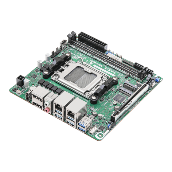
Page 10: Motherboard Layout
1.3 Motherboard Layout HEATER1 CPU_FAN1 CHA_FAN1 USB2_0 ATXPWR1 ATX12V1 BAT1 Bottom: Top: Mic In Line Out USB 3. Gen2 LAN1 Top: USB3_1 Bottom: USB3_0 USB 3. Gen2 Top: USB3_3 LAN2 Bottom: USB3_2 PWR_LOSS1 Gen2 Top: USB3_5 Bottom: USB3_4 M2_E1 M2_M1 BIOS HD_ADUIO1 SIM1... - Page 11 IMB-A1002 EDP0 ESPI1 M2_B1...
- Page 12 1 : HEATER1 Header (HEATER1) 2 : Battery Connector (BAT1) 3 : 4-pin Power Connector (ATX12V1) 4 : CPU FAN Connector (+12V) (CPU_FAN1) 5 : CHA FAN Connector (+12V) (CHA_FAN1) 6 : USB 2.0 Connector (USB2_0) 7 : 24-pin ATX Power Input Connector (ATXPWR1) 8 : SMBUS_TEST1 9 : USB 2.0 Connector (USB2_2_4) 10 : System Panel Header (PANEL1)
-
Page 13: I/O Panel
IMB-A1002 1.4 I/O Panel DisplayPort (DP1) USB 3.2 Gen2 Ports DisplayPorts (DP2_3) Top: USB3_5 Top: DP3 Bottom: USB3_4 Bottom: DP2 USB 3.2 Gen2 Ports Audio Output : Green – Line Out Top: USB3_3 RJ45 LAN Port (LAN1)* Bottom : USB3_2 RJ45 LAN Port (LAN2)* USB 3.2 Gen2 Ports... -
Page 14: Block Diagram
1.5 Block Diagram IMB-A1002 U-DIMM DDR5 Channel A (A1) 5200MHz Channel B U-DIMM DDR5 5200MHz (B1) DP 0 eDP connector PCIe Gen5 [0:15] DP 1 PCIe x16 Slot Display port 1 DP++ Connector AUX SW APU PCIe [19:16] DP 2... -
Page 15: Chapter 2 Installation
IMB-A1002 Chapter 2 Installation This is a Mini-ITX (6.7-in x 6.7-in x 1.5-in, 17.0 cm x 17.0 cm x 3.7 cm) form factor mother- board. Before you install the motherboard, study the configuration of your chassis to ensure that the motherboard fits into it. -
Page 16: Installation Of Memory Modules
2.3 Installation of Memory Modules IMB-A1002 provides two 288-pin DDR5 (Double Data Rate 5) LONG-DIMM slots, and supports Dual Channel Memory Technology. Please make sure to disconnect the power supply before adding or removing LONG- DIMMs or the system components. - Page 17 IMB-A1002 Open the DIMM slot latch. Aligh the notch. Carefully press down until the DIMM slides into the slot. The latche snaps back into place.
-
Page 18: Expansion Slots
2.4 Expansion Slots There are one PCI Express slot, three M.2 sockets, and one SIM socket on this motherboard. PCIE slot: PCIE1 (PCIE 5.0 x16 slot) is used for PCI Express x16 lane width cards. M.2 sockets: 1 x M.2 (Key E, 2230) with PCIe Gen3 x1, USB 2.0 for Wireless 1 x M.2 (Key M, 2242/2280) with PCIe Gen4 x4, SATA3 and USB 2.0 1 x M.2 (Key B, 3042/3052) with PCIe Gen3 x1, USB 3.0, USB 2.0 and SIM socket for 4G/5G... -
Page 19: Jumpers Setup
IMB-A1002 2.5 Jumpers Setup The illustration shows how jumpers are setup. When the jumper cap is placed on pins, the jumper is “Short.” If no jumper cap is placed on pins, the jumper is “Open. ” The illustration shows a 3-pin jumper whose pin1 and pin2 are “Short”... - Page 20 NOTE: CLRMOS1 allows you to clear the data in CMOS. To clear and reset the system param- eters to default setup, please turn off the computer and unplug the power cord from the power supply. After waiting for 15 seconds, use a jumper cap to short pin 2 and pin 3 on CLRMOS1 for 5 seconds.
-
Page 21: Onboard Headers And Connectors
IMB-A1002 2.6 Onboard Headers and Connectors Onboard headers and connectors are NOT jumpers. Do NOT place jumper caps over these headers and connectors. Placing jumper caps over the headers and connectors will cause per- manent damage to the motherboard! Heater Header... - Page 22 Chassis Fan Connector (+12V) Signal Name (4-pin CHA_FAN1) +12V (see p. 4, No. 5) CHA_FAN_SPEED FAN_SPEED_CONTROL The board offers one 4-pin chassis fan (Smart Fan) connector which is compatible with 3-pin chassis fan. If you connect a 3-pin chassis fan to the chassis fan connector on this mother- board, please connect it to pin 1-3.
- Page 23 IMB-A1002 USB 2.0 Connector Signal Name Signal Name USB_PWR USB_PWR (9-pin USB2_2_4) (see p. 5, No. 9) DUMMY The board provides one internal 2.54mm pitch header, and the connector can support two USB 2.0 ports. The maximum current per port is 0.5A.
- Page 24 Internal COM Port Headers (RS232/422/485)* Signal Name Signal Name DDCD# RRXD (9-pin COM1, COM2) TTXD DDTR# (see p. 4, No. 12) DDSR# COM1 RRTS# CCTS# COM2 There are two 2.54mm-pitch COM port headers (COM1, 2), which support RS232/422/485. The maximum current for per port is 1A, and the power supply of pin 9 is either 5V or 12V. Use COM Port PWR Setting Jumper to set the power for COM port pin 9.
- Page 25 IMB-A1002 SPDIF Header Signal Name (3-pin SPDIF1) (see p. 4 , No. 20) SPDIF OUT SPDIF header, providing SPDIF audio output to HDMI VGA card, allows the system to connect HDMI Digital TV/projector/LCD devices. Please connect the SPDIF connector of HDMI VGA card to this header.
- Page 26 EDP0 Header Signal Name (40-pin EDP0) (see p. 5, No. 25) eDP_TX#3_CON eDP_TX3_CON eDP_TX#2_CON eDP_TX2_CON eDP_TX#1_CON eDP_TX1_CON eDP_TX#0_CON eDP_TX0_CON eDP_AUX_CON eDP_AUX#_CON LCD_VCC (+3V) LCD_VCC (+3V) LCD_VCC (+3V) LCD_VCC (+3V) eDP_HPD_CON eDP_BKLTEN eDP_BKLTCTL_R SMB_DATA_MAIN SMB_CLK_MAIN LCD_BLT_VCC (+12V) LCD_BLT_VCC (+12V) LCD_BLT_VCC (+12V) LCD_BLT_VCC (+12V)
-
Page 27: Chapter 3 Uefi Setup Utility
Chapter 3 UEFI SETUP UTILITY 3.1 Introduction ASRock Industrial UEFI (Unified Extensible Firmware Interface) is a BIOS utility which offers tweak-friendly options in an advanced viewing interface. This BIOS utility can perform the Power-On Self-Test (POST) during system startup, re- cord hardware parameters of the system, load operating system, and so on. -
Page 28: Uefi Menu Bar
3.1.2 UEFI Menu Bar The top of the screen has a menu bar with the following selections: Main For setting system time/date information For advanced system configurations Advanced H/W Monitor Displays current hardware status Security For security settings Boot For configuring boot settings and boot priority Exit Exit the current screen or the UEFI Setup Utility Because the UEFI software is constantly being updated, the following UEFI setup... -
Page 29: Navigation Keys
IMB-A1002 3.1.3 Navigation Keys Use < > key or < > key to choose among the selections on the menu bar, and use < > key or < > key to move the cursor up or down to select items, then press <Enter>... -
Page 30: Main Screen
3.2 Main Screen When you enter the UEFI SETUP UTILITY, the Main screen will appear and display the system overview. Because the UEFI software is constantly being updated, the following UEFI setup screens and descriptions are for reference purpose only, and they may not exactly match what you see on your screen. -
Page 31: Advanced Screen
IMB-A1002 3.3 Advanced Screen I n t h i s s ec t ion, you may s et t he con f ig u r at ions for t he fol low i ng items: CPU Configuration, Chipset Configuration, Storage Configuration, Super IO Configuration,... -
Page 32: Cpu Configuration
3.3.1 CPU Configuration PSS Support Enable/disable the generation of ACPI _PPC, _PSS, and _PCT objects. Core Performance Boost Core Performance Boost controls whether the processor transitions to a higher frequency than the processor's rated speed if the processor has available power and is within temperature specifications. -
Page 33: Chipset Configuration
IMB-A1002 3.3.2 Chipset Configuration IOMMU Enable/Disable IOMMU Support. Primary Graphics Adapter The option allows you to select a primary VGA. Configuration options: [Onboard] [PCI Express] (Options vary when you have installed a graphics card on your motherboard.) Share Memory Share memory allows you to configure the size of memory that is allocated to the integrated graphics processor when the system boots up. - Page 34 Re-Size BAR Support If system has Resizable BAR capable PCIe Devices, this option enables or disables Resizable BAR Support. SR-IOV Support If system has SR-IOV capable PCIe Devices, this option Enables or Disables Single Root IO Virtualization Support. Configuration options: [Enabled] [Disabled] Onboard HD Audio Onboard HD Audio allows you to enable or disable the onboard HD audio controller.
- Page 35 IMB-A1002 Deep S5 Mobile platforms support Deep S5 in DC only and desktop platforms support Deep S5 in AC only. The default value is [Disabled]. Configuration options: [Auto] [Disabled]...
-
Page 36: Storage Configuration
3.3.3 Storage Configuration SATA Controller(s) The option allows you to enable or disable the SATA controllers. Configuration options: [Enabled] [Disabled] SATA Mode AHCI supports new features that improve performance. Configuration option: [AHCI] Hard Disk S.M.A.R.T. S.M.A.R.T stands for Self-Monitoring, Analysis, and Reporting Technology. It is a monitoring system for computer hard disk drives to detect and report on various indicators of reliability. -
Page 37: Super Io Configuration
IMB-A1002 3.3.4 Super IO Configuration COM1 Configuration Use this to set parameters of COM1. Type Select Use this to select COM1 port type: [RS232], [RS422] or [RS485]. COM2 Configuration Use this to set parameters of COM2. Type Select Use this to select COM2 port type: [RS232], [RS422] or [RS485]. -
Page 38: Acpi Configuration
3.3.5 ACPI Configuration Suspend to RAM Suspend to R A M a l lows you to select [Disabled] for ACPI suspend t y pe S1. It is recommended to select [Auto] for ACPI S3 power saving. Configuration options: [Auto] [Disabled] Onboard LAN Power On Use this item to enable or disable onboard LAN to turn on the system from the power-soft- off mode. -
Page 39: Usb Configuration
IMB-A1002 3.3.6 USB Configuration USB Power Control Use this option to control USB power. M.2 Key_B USB Function The item enables or disables M.2 Key_B USB function. -
Page 40: Trusted Computing
3.3.7 Trusted Computing NOTE: Options vary depending on the version of your connected TPM module. Security Device Support Security Device Support allows you to enable or disable BIOS support for security device. O.S. will not show Security Device. TCG EFI protocol and INT1A interface will not be available. - Page 41 IMB-A1002 Pending Operation Pending Operation allows you to schedule an Operation for the Security Device. NOTE: Your computer will reboot during restart in order to change State of the Device. Configuration options: [None] [TPM Clear] Platform Hierarchy This item allows you to enable or disable Platform Hierarchy.
-
Page 42: Hardware Health Event Monitoring Screen
3.4 Hardware Health Event Monitoring Screen This section allows you to monitor the status of the hardware on your system, including the parameters of the CPU temperature, motherboard temperature, CPU fan speed, chassis fan speed, and the critical voltage. NOTE: Options vary depending on the features of your motherboard. CPU_Fan 1 Setting This item allows you to select a fan mode for CPU Fan 1. -
Page 43: Security Screen
IMB-A1002 3.5 Security Screen In this section you may set or change the supervisor/user password for the system. You may also clear the user password. Supervisor Password Set or change the password for the administrator account. Only the administrator has the authority to change the settings in the UEFI Setup Utility. -
Page 44: Boot Screen
3.6 Boot Screen This section displays the available devices on your system for you to configure the boot settings and the boot priority. Boot Option #1 The item allows you to set the system boot order. Boot From Onboard LAN The item allows the system to be waked up by the onboard LAN. -
Page 45: Exit Screen
IMB-A1002 3.7 Exit Screen Save Changes and Exit When you select this option, the following message “Save configuration changes and exit setup?” will pop out. Select [Yes] to save the changes and exit the UEFI SETUP UTILITY. Discard Changes and Exit When you select this option, the following message “Discard changes and exit setup?”...
Need help?
Do you have a question about the IMB-A1002 and is the answer not in the manual?
Questions and answers