Table of Contents
Advertisement
Quick Links
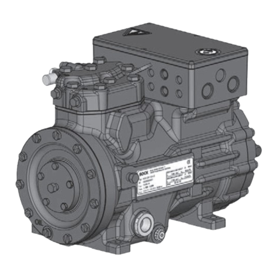
Reciprocating Compressor
BOCK UL-HGX
Assembly instructions
(Translation of the original instructions)
96545-02.2024-Us
UL-HGX12P/60 S 0,7
UL-HGX12P/75 ML 1
UL-HGX12P/75 S 2
UL-HGX12P/90 ML 2
Bock GmbH, Benzstr. 7, 72636 Frickenhausen, Germany
Phone: +49 7022 9454-0, Fax: +49 7022 9454-137
www.bock.de, service@bock.de
BOCK
®
12
P
UL-HGX12P/90 S 2
UL-HGX12P/110 ML 2
UL-HGX12P/110 S 3
colour the world
of tomorrow
Advertisement
Table of Contents

Related Manuals for BOCK UL-HGX12P


Summary of Contents for BOCK UL-HGX12P
- Page 1 UL-HGX12P/90 S 2 UL-HGX12P/75 ML 1 UL-HGX12P/110 ML 2 UL-HGX12P/75 S 2 UL-HGX12P/110 S 3 UL-HGX12P/90 ML 2 Bock GmbH, Benzstr. 7, 72636 Frickenhausen, Germany Phone: +49 7022 9454-0, Fax: +49 7022 9454-137 www.bock.de, service@bock.de BOCK ® colour the world...
-
Page 2: Table Of Contents
It must be passed onto the end customer along with the unit in which the compressor is installed. This document is subject to the copyright of BOCK GmbH, Germany. The information provided in this manual is subject to change and improvements without notice. - Page 3 Contents Page Compressor assembly ..................... 9 Storage and transport ......................9 Setting up .......................... 9 Pipe connections ......................10 Pipes ..........................10 Laying suction and pressure lines ..................10 Operating the shut-off valves ................... 11 Operating Mode of the lockable service connections ............11 Suction pipe filter and filter drier ..................
-
Page 4: Safety
1| Safety 1.1 Identification of safety instructions Indicates a dangerous situation which, if not avoided, will cause immediate fatal or serious injury. Indicates a dangerous situation which, if not avoided, may cause fatal or serious injury. Indicates a dangerous situation which, if not avoided, may cause fairly severe or minor injury. -
Page 5: Intended Use
These assembly instructions describe the standard version of the compressor named in the title manufactured by Bock. Bock refrigerating compressors are intended for installation in a ma- chine (within the EU according to the EU Directives 2006/42/EC Machinery Directive, 2014/68/ EU Pressure Equipment Directive, outside the EU according to the respective national regulations and guidelines). -
Page 6: Product Description
2| Product description 2.1 Short description • Semi-hermetic two-cylinder reciprocating compressor with oil pump lubrication. • Suction gas cooled drive motor. The stream of refrigerant sucked out of the evaporator flows over the motor and cools it intensively. In this way, the motor can be kept at a relatively low temperature level, particularly under high loads. -
Page 7: Name Plate (Example)
2.2 Name plate (example) BOCK Bock GmbH, Benzstr. 7 72636 Frickenhausen, Germany thermally protected system Type :HGX12P/110 S 3 380-420 Y/YY : UL-HGX12P/110 S 3 332 cfh 180,0 : AS35830A001 10,6 / 6,1A 440-480 Y/YY Y: 26A 217,2 399 cfh... -
Page 8: Areas Of Application
More informations about approved refrigerants on Bock compressor selection tool VAP (vap.bock.de). 3.2 Oil charge The compressors are filled at the factory with the following oil type: BOCK lub E55 For refilling, we recommend the above oil types. See also section 7.4. -
Page 9: Compressor Assembly
4| Compressor assembly New compressors are factory-filled with inert gas. Leave this service charge in the compressor for as long as possible and pre- vent the ingress of air. Check the compressor for transport damage before starting any work. 4.1 Storage and transport Storage at -30°C...+70°C (-22°F...+158°F), maximum permissible relative humidity 10% - 95%, no condensation Do not store in a corrosive, dusty, vaporous atmosphere or in a com-... -
Page 10: Pipe Connections
4| Compressor assembly 4.3 Pipe connections Damage possible. Do not solder as long as the compressor is under pressure. Superheating can damage the valve. Remove the pipe supports therefore from the valve for soldering and accordingly cool the valve body during and after soldering. Only solder using inert gas to inhibit oxidation products (scale). -
Page 11: Operating The Shut-Off Valves
4| Compressor assembly 4.6 Operating the shut-off valves Before opening or closing the shut-off valve, release the valve spindle seal by approx. 1 / 4 of a turn counter-clockwise. After activating the shut-off valve, re-tighten the adjustable valve spindle seal clockwise. Tighten Release Valve spindle seal... -
Page 12: Suction Pipe Filter And Filter Drier
4| Compressor assembly 4.8 Suction pipe filter and filter drier For systems with long pipes and higher degree of contamination, a filter on the suction-side is recommended. The filter has to be renewed depending on the degree of contamination (reduced pressure loss). Moisture in the refrigeration circuit can lead to crystal and hydrate formation. For this reason, we recommend using a filter drier and a sight glass with a moisture indicator. -
Page 13: Connection For The Driving Motor
5| Electrical connection 5.3 Connection for the driving motor The compressor is designed with a motor for star-delta circuits. Designation on the name plate ∆ / Y Star-delta start-up is only possible on 230 V voltage supply. Example: 230 V ∆ 400 V Y L1 L2 Direct start... -
Page 14: Circuit Diagramm For Direct Start 230 V ∆ / 400 V Y
5.4 Circuit diagramm for direct start 230 V ∆ / 400 V Y FC1.1 I> I> I> FC1.1 L3 N PE -EC1 Θ B1 B2 INT69G Compressor terminal box Anschlußkasten Verdichter Fig. 11 Cold conductor (PTC sensor) motor winding Thermal protection thermostat (PTC sensor) Load circuit safety switches Control power circuit fuse High pressure safety monitor... - Page 15 L1.1 L2.1 L3.1 L1.2 P> Θ Θ Main switch Control voltage switch Compressor motor Compressor contactor INT69 G Electronic trigger unit INT69 G Oil sump heater...
-
Page 16: Electronic Trigger Unit Int69 G
5| Electrical connection 5.5 Electronic trigger unit INT69 G The compressor motor is fitted with cold conductor temperature sensors (PTC) connected to the electronic trigger unit INT69 G in the terminal box. In case of excess temperature in the motor winding, the INT69 G deactivates the motor contactor. -
Page 17: Oil Sump Heater (Accessories)
5| Electrical connection 5.8 Oil sump heater (accessories) When the compressor is at a standstill, refrigerant diffuses into the lubricating oil of the compressors housing, depending on pressure and ambient temperature. This reduces the lubricating capacity of the oil. When the compressor starts up, the refrigerant contained in the oil evaporates out through the reduction in pressure. -
Page 18: Commissioning
6| Commissioning 6.1 Preparations for start-up To protect the compressor against inadmissible operating conditions, high pressure and low pressure pressostats are mandatory on the installation side. The compressor has undergone trials in the factory and all functions have been tested. There are therefore no special running-in instructions. -
Page 19: Refrigerant Charge
6| Commissioning 6.5 Refrigerant charge Wear personal protective clothing such as goggles and protective gloves! Make sure that the suction and pressure line shut-off valves are open. With the compressor switched off, add the liquid refrigerant directly to the condenser or receiver, breaking the vacuum. -
Page 20: Maintenance
It is for this reason, that we only recommend the use of oil from Bock! Bock assumes no liability for any damage arising from alternative oil types. -
Page 21: Technical Data
Max. power consumption Max. operating current 220-240 V ∆ / 380-420 V Y - 3 - 50 Hz Voltage 265-290 V ∆ / 440-480 V Y - 3 - 60 Hz Displacement (1450 / 1740 rpm) No. of cylinders Type UL-HGX12P/... -
Page 22: Dimensions And Connections
14541 (14549) HG12P/60-4 S HC 14541 (14549) HG12P/60-4 S HC 10893 10893 HGX12P/60 S 0,7 LG HGX12P/60 S 0,7 LG 14678 14678 UL-HGX12P/60 S 0,7 UL-HGX12P/60 S 0,7 14713 14713 HG(X)12P/75-4 HG(X)12P/75-4 14542 (14550) HG12P/75-4 HC 14542 (14550) HG12P/75-4 HC... -
Page 23: Declaration Of Incorporation
We, as manufacturer, declare in sole responsibility that the incomplete machinery Name: Semi-hermetic compressor Types: HG(X)12P/60-4 S (HC) ......HG(X)88e/3235-4(S) (HC) UL-HGX12P/60 S 0,7......UL-HGX66e/2070 S 60 HGX12P/60 S 0,7 LG ......HGX88e/3235 (ML/S) 95 LG HG(X)22(P)(e)/125-4 A ......HG(X)34(P)(e)/380-4 (S) A HGX34(P)(e)/255-2 (A) ....... HGX34(P)(e)/380-2 (A)(K) HA(X)12P/60-4 ........HA(X)6/1410-4 HAX22e/125 LT 2 LG ...... - Page 24 We, as manufacturer, declare in sole responsibility that the partly completed machinery Name: Semi-hermetic compressor Types: HG(X)12P/60-4 S (HC) ......HG(X)88e/3235-4(S) (HC) UL-HGX12P/60 S 0,7......UL-HGX88e/3235 S 95 HGX12P/60 S 0,7 LG ......HGX88e/3235 (ML/S) 95 LG HG(X)22(P)(e)/125-4 A ......HG(X)34(P)(e)/380-4 (S) A HGX34(P)(e)/255-2 (A) ....... HGX34(P)(e)/380-2 (A)(K) HA(X)22e/125-4 ........HA(X)6/1410-4 HAX22e/125 LT 2 LG ......
-
Page 25: Ul-Certificate Of Compliance
Dear customer, if you have any questions about installation, operation and accessories, please contact our technical service or specialist wholesaler and/or our representative. The Bock service team can be contacted by phone, +49 (0)7022 9454-0 or via service@bock.de Yours sincerely, Bock GmbH... - Page 26 BOCK ® Bock GmbH Benzstraße 7 72636 Frickenhausen Germany Phone +49 7022 9454-0 +49 7022 9454-137 www.bock.de © Bock GmbH. All rights reserved. Subject to modifications.
Need help?
Do you have a question about the UL-HGX12P and is the answer not in the manual?
Questions and answers