Table of Contents
Advertisement
Quick Links
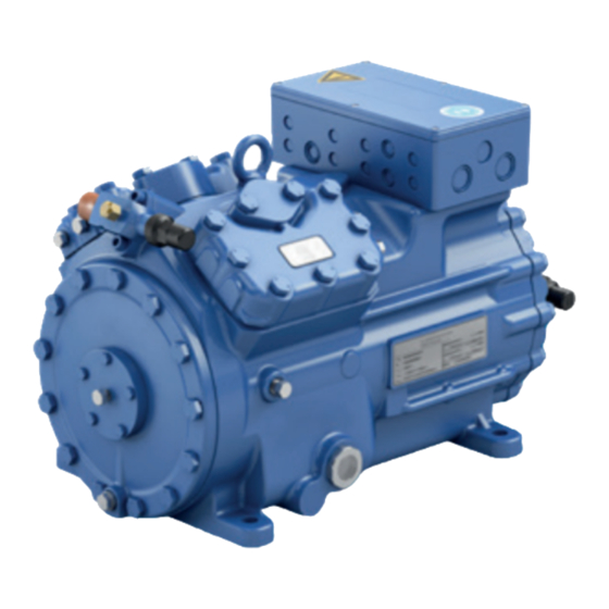
Reciprocating Compressor
BOCK UL-HGX
Assembly instructions
(Translation of the original instructions)
96546-02.2024-Us
-
UL
HGX22e/125 ML 2
-
UL
HGX22e/125 S 3
UL-HGX22e/160 ML 2
UL-HGX22e/160 S 3
UL-HGX22e/190 ML 3
UL-HGX22e/190 S 4
Bock GmbH, Benzstr. 7, 72636 Frickenhausen, Germany
Phone: +49 7022 9454-0, Fax: +49 7022 9454-137
www.bock.de, service@bock.de
BOCK
®
22
e/UL-HGX 34 e
UL-HGX34e/215 ML 3
UL-HGX34e/215 S 5
UL-HGX34e/255 ML 4
UL-HGX34e/255 S 6
UL-HGX34e/315 ML 5
UL-HGX34e/315 S 7
UL-HGX34e/380 ML 6
UL-HGX34e/380 S 9
colour the world
of tomorrow
Advertisement
Table of Contents

Related Manuals for BOCK UL-HGX22e Series


Summary of Contents for BOCK UL-HGX22e Series
- Page 1 UL-HGX22e/190 ML 3 UL-HGX34e/315 ML 5 UL-HGX22e/190 S 4 UL-HGX34e/315 S 7 UL-HGX34e/380 ML 6 UL-HGX34e/380 S 9 Bock GmbH, Benzstr. 7, 72636 Frickenhausen, Germany Phone: +49 7022 9454-0, Fax: +49 7022 9454-137 www.bock.de, service@bock.de BOCK ® colour the world...
-
Page 2: Table Of Contents
It must be passed onto the end customer along with the unit in which the compressor is installed. This document is subject to the copyright of BOCK GmbH, Germany. The information provided in this manual is subject to change and improvements without notice. - Page 3 Contents Page Compressor assembly ..................... 9 Storage and transport ......................9 Setting up .......................... 9 Pipe connections ......................10 Pipes ..........................10 Laying suction and pressure lines ..................10 Operating the shut-off valves ................... 11 Operating mode of the lockable service connections ............12 Suction pipe filter and filter drier ..................
-
Page 4: Safety
1| Safety Identification of safety instructions Indicates a dangerous situation which, if not avoided, will cause immediate fatal or serious injury. Indicates a dangerous situation which, if not avoided, may cause fatal or serious injury. Indicates a dangerous situation which, if not avoided, may cause fairly severe or minor injury. -
Page 5: Intended Use
These assembly instructions describe the standard version of the compressor named in the title manufactured by Bock. Bock refrigerating compressors are intended for installation in a ma- chine (within the EU according to the EU Directives 2006/42/EC Machinery Directive, 2014/68/ EU Pressure Equipment Directive, outside the EU according to the respective national regulations and guidelines). -
Page 6: Product Description
2| Product description Short description • UL-HGX22e: Semi-hermetic two-cylinder reciprocating compressor with oil pump lubrication. • UL-HGX34e: Semi-hermetic four-cylinder reciprocating compressor with oil pump lubrication. • Suction gas cooled drive motor. • The stream of refrigerant sucked out of the evaporator flows over the motor and cools it intensively. -
Page 7: Name Plate (Example)
2| Product description Name plate (example) Bock GmbH, Benzstr. 7 BOCK 72636 Frickenhausen, Germany thermally protected system Type : UL-HGX34e/315 ML 5 : AS38125A001 665 cfh 107,0 A 21,1/12,2A 111A YY: 335,0 A 798 cfh 19/28 Oil: BOCK lub E55 LP/HP = 276/406 psig Öl: BOCK lub E55... -
Page 8: Areas Of Application
More informations about approved refrigerants on Bock compressor selection tool VAP (vap.bock.de). Oil charge The compressors are filled at the factory with the following oil type: BOCK lub E55 For refilling, we recommend the above oil types. See also section 7.4. -
Page 9: Compressor Assembly
3| Areas of application Maximum admissible operating pressure (LP/HP) LP = Low pressure 19/28 bar (276/406 psig) HP = High pressure 4| Compressor assembly New compressors are factory-filled with inert gas. Leave this service charge in the compressor for as long as possible and pre- vent the ingress of air. -
Page 10: Pipe Connections
4| Compressor assembly Pipe connections Damage possible. Do not solder as long as the compressor is under pressure. Superheating can damage the valve. Remove the pipe supports therefore from the valve for soldering and accordingly cool the valve body during and after soldering. Only solder using inert gas to inhibit oxidation products (scale). -
Page 11: Operating The Shut-Off Valves
4| Compressor assembly A rule of thumb: Always lay the first pipe section starting from the shut-off valve downwards and parallel to the drive shaft. Rigid As short as fixed point possible Fig. 6 Operating the shut-off valves Before opening or closing the shut-off valve, release the valve spindle seal by approx. 1 / 4 of a turn counter-clockwise. -
Page 12: Operating Mode Of The Lockable Service Connections
4| Compressor assembly Operating mode of the lockable service connections Service connec- tion closed Opening the shut-off valve: Spindle: turn to the left (counter- Pipe connection clockwise) as far as it will go. Connection Spindle —> Shut-off valve completely blocked opened / service connection Compressor Fig. -
Page 13: Electrical Connection
5| Electrical connection General safety Risk of electric shock! High voltage! Only carry out work when the electrical system is disconnected from the power supply! When attaching accessories with an electrical cable, a minimum bending radius of 3 x the cable diameter must be maintained for laying the cable. -
Page 14: Connection Of The Driving Motor
5| Electrical connection Connection of the driving motor The compressor is designed with a motor for star-delta circuits. Designation on the name plate ∆ / Y... - Page 15 5| Electrical connection Star-delta start-up is only possible on 230 V voltage supply. Example: L1 L2 230 V ∆ 400 V Y Direct start Star-delta start Direct start only L1 L2 L1 L2 L1 L2 L1 L2 Insulators 96027-11.06-DGbF Insulators The connection examples shown refer to the standard version.
-
Page 16: Circuit Diagramm For Direct Start 230 V ∆ / 400 V Y
Circuit diagramm for direct start 230 V ∆ / 400 V Y FC1.1 I> I> I> FC1.1 L3 N PE -EC1 Θ B1 B2 INT69G Compressor terminal box Anschlußkasten Verdichter Fig. 11 Cold conductor (PTC sensor) motor winding Thermal protection thermostat (PTC sensor) Load circuit safety switches Control power circuit fuse High pressure safety monitor... - Page 17 L1.1 L2.1 L3.1 L1.2 P> Θ Θ Main switch Control voltage switch Compressor motor Compressor contactor INT69 G Electronic trigger unit INT69 G Oil sump heater...
-
Page 18: Electronic Trigger Unit Int69 G
5| Electrical connection Electronic trigger unit INT69 G The compressor motor is fitted with cold conductor temperature sensors (PTC) connected to the electronic trigger unit INT69 G in the terminal box. In case of excess temperature in the motor winding, the INT69 G deactivates the motor contactor. Once cooled, it can be restarted only if the electronic lock of the output relay (terminals B1+B2) is released by interrupting the supply voltage. -
Page 19: Function Test Of The Trigger Unit Int69 G
5| Electrical connection Function test of the trigger unit INT69 G Before commissioning, after troubleshooting or making changes to the control power circuit, check the functionality of the trigger unit. Perform this check using a continuity tester or gage. Relay position INT69 G Gage state Relay position Deactivated state... -
Page 20: Selection And Operation Of Compressors With Frequency Converters
5| Electrical connection 5.10 Selection and operation of compressors with frequency converters For safe operation of the compressor, the frequency converter must be able to apply an overload of at least 140% of the compressor's maximum current (I-max.) for at least 3 seconds. When using frequency converters, the following things must also be observed: 1. -
Page 21: Commissioning
6| Commissioning Preparations for start-up To protect the compressor against inadmissible operating conditions, high pressure and low pressure pressostats are mandatory on the installation side. The compressor has undergone trials in the factory and all functions have been tested. There are therefore no special running-in instructions. -
Page 22: Start-Up
6| Commissioning Make sure that the suction and pressure line shut-off valves are open. With the compressor switched off, add the liquid refrigerant directly to the condenser or receiver, breaking the vacuum. If the refrigerant needs topping up after starting the compressor, it can be topped up in vapor form on the suction side, or, taking suitable precautions, also in liquid form at the inlet to the evapora- tor. -
Page 23: Maintenance
It is for this reason, that we only recommend the use of oil from Bock! Bock assumes no liability for any damage arising from alternative oil types. -
Page 24: Accessories
8 | Accessories 8.1 Capacity regulator If the capacity regulator is installed at the factory, it is subsequently installed and connected by the customer. CR 1 Fig. 15 HG34e Fig. 16 Fig. 17 Delivery condition 1 (from the factory): Before commissioning, the blind flange with Cylinder cover prepared for capacity regulator. - Page 25 Information about the use, operation, maintenance and servicing of the components is available in the printed literature or on the internet under www.bock.de. For the capacity regulator a step protection is optional available, Art-Nr.
-
Page 26: Technical Data
9 | Technical data Sound pressure level Oil charge (sight glass center) Oil charge (ex works) Suction line Discharge line Weight permissible 30 - 70 frequency range Starting current (rotor locked) Max. power consumption Max. operating current 220-240 V ∆ / 380-420 V Y - 3 - 50 Hz Voltage 265-290 V ∆... - Page 27 9 | Technical data Sound pressure level Oil charge (sight glass center) Oil charge (ex works) Suction line Discharge line Weight permissible 25 - 70 frequency range Starting current (rotor locked) Max. power consumption Max. operating current 220-240 V ∆ / 380-420 V Y - 3 - 50 Hz Voltage 265-290 V ∆...
-
Page 28: Dimensions And Connections
Offenders will be held liable for the prohibited. Offenders will be held liable for the payment of damages. All rights reserved in the event payment of damages. All rights reserved in the event BOCK Zust. / Rev. Zust. / Rev. Änd.-Nr. / Mod-No. - Page 29 10 | Dimensions and connections UL-HGX34e + 0,08 Anschlüsse / 11,1 Connections + 0,08 + 0,08 Anschlüsse / Anschlüsse / Saugabsperrventil 11,1 11,1 Connections Connections Suction line valve, Center of gravity Saugabsperrventil, R Saugabsperrvent Druckabsperrventi Suction line valve, tu Suction line valve Discharge line valv Druckabsperrventil, R Druckabsperrven...
-
Page 30: Declaration Of Incorporation
11 | Declaration of incorporation ® Declaration of incorporation for incomplete machinery in accordance with EC Machinery Directive 2006/42/EC, Annex II 1. B Manufacturer: Bock GmbH Benzstraße 7 72636 Frickenhausen, Germany We, as manufacturer, declare in sole responsibility that the incomplete machinery Name:... - Page 31 Declaration of incorporation of partly completed machinery in accordance with UK Statutory Instrument Supply of Machinery (Safety) Regulations 2008, Annex II 1. B Manufacturer: Bock GmbH Benzstraße 7 72636 Frickenhausen, Germany We, as manufacturer, declare in sole responsibility that the partly completed machinery...
-
Page 32: Ul-Certificate Of Compliance
12 | UL-Certificate of Compliance Dear customer, the UL-Certificate of Compliance can be downloaded by the following QR-Code: https://vap.bock.de/stationaryapplication/Data/ DocumentationFiles/UL-Certificateofconformity.pdf... -
Page 33: Service
Dear customer, if you have any questions about installation, operation and accessories, please contact our technical service or specialist wholesaler and/or our representative. The Bock service team can be contacted by phone, +49 (0)7022 9454-0 or via service@bock.de Yours sincerely, Bock GmbH... - Page 34 BOCK ® Bock GmbH Benzstraße 7 72636 Frickenhausen Germany Phone +49 7022 9454-0 +49 7022 9454-137 www.bock.de © Bock GmbH. All rights reserved. Subject to modifications.
Need help?
Do you have a question about the UL-HGX22e Series and is the answer not in the manual?
Questions and answers