Table of Contents
Advertisement
Quick Links
BOCK FK
Maintenance manual
96003-01.2022-Gb
Translation of the original instructions
FK50/460 N
FK50/555 N
FK50/460 K
FK50/555 K
FK50/460 TK
FK50/555 TK
FKX50/460 N
FKX50/555 N
FKX50/460 K
FKX50/555 K
FKX50/460 TK
FKX50/555 TK
BOCK
®
50
FK50/660 N
FK50/660 K
FK50/660 TK
FKX50/660 N
FKX50/660 K
FKX50/660 TK
FK50/775 N
FK50/830 N
FK50/775 K
FK50/830 K
FK50/775 TK
FKX50/775 N
FKX50/830 N
FKX50/775 K
FKX50/830 K
FKX50/775 TK
colour the world
of tomorrow
FK50/980 N
FK50/980 K
FKX50/980 N
FKX50/980 K
- 1 -
Advertisement
Table of Contents

Related Manuals for BOCK FK50


Summary of Contents for BOCK FK50
- Page 1 BOCK FK Maintenance manual 96003-01.2022-Gb Translation of the original instructions FK50/460 N FK50/555 N FK50/660 N FK50/775 N FK50/830 N FK50/980 N FK50/460 K FK50/555 K FK50/660 K FK50/775 K FK50/830 K FK50/980 K FK50/460 TK FK50/555 TK FK50/660 TK...
-
Page 2: Table Of Contents
Read these instructions before assembly and before using the compressor. This will avoid misunderstandings and prevent damage. Improper assembly and use of the compressor can result in serious or fatal injury. Observe the safety instructions contained in these instructions. Bock GmbH Benzstrasse 7 72636 Frickenhausen Germany... - Page 3 Contents Abnormal running noise from compressor Malfunction of the electromagnetic clutch Installation of service kits Shaft seal, Part no. 80023 Emptying the oil reseroir, Version ID 007 - 014, Clamping ring with oil felt Capacity regulation, capacity regulation valve Part no. 07541 Valve plate Electromagnetic clutch Compressor defects...
-
Page 4: Introduction
Introduction Introduction This maintenance manual is intended to make the repair and maintenance of the FK50 easier for the servicing personnel. The maintenance manual contains a complete description of each work step for the disassembly and assembly of the compressor components. Each step must be carefully adhered to in order tu ensure a reliable repair. -
Page 5: Safety Instructions
Safety Safety instructions Target group of these instructions • Work on the compressor may only be carried out by persons whose technical training, skills and experience along with their knowledge of pertinent regulations and documentation means that they are capable of assessing the work to be carried out and detecting any possible dangers •... - Page 6 Safety General safety instructions GEFAHR Danger from electric shock Compressors contain live parts. Touching these parts can cause electric shock and lead to serious or even fatal injuries. • Disconnect the compressor from the power supply before commencing work! • Turn the main switch of the plant to "0" (OFF)! •...
- Page 7 Safety WARNUNG Danger from pressure Compressors are pressurized machines containing very high pressures. They must therefore be handled with extreme caution and care. Serious and even fatal injuries can occur. • The maximum permissible overpressure must not be exceeded, even for testing purposes! •...
-
Page 8: Product Description
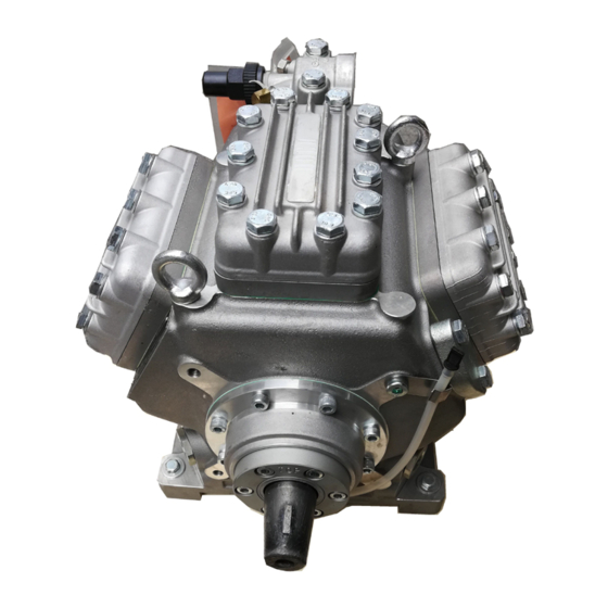
Product description Product description Series FK50 vehicle compressors are designed for mobile applications. Short description Three design variations are available for different areas of application: > For air conditioning the K Design > For air conditioning or normal cooling the N Design >... -
Page 9: Short Description, Nameplate, Type Code
Main and functional parts 1. Cylinder cover 12. Baseplate 2. Valve plate 13. Suction shut-off valve 3. Compressor casing (FK50/660, 775, 830 and 980 4. Integrated leak oil collector with 2 suction shut-off valves) 5. Location hole for fitting magnetic clutch 14. Oil pump 6. Shaft end 15. Oil drain plug / oil filter... -
Page 10: Dimension Drawing, Connections
Product description Dimension drawing Dimensions in mm - additional SV at FK50/660, 775, 830 and 980 standart - () = K-Design Centre of gravity Shaft end oil tube Connections Suction side connection, not lockable 1/8“ NPTF Suction side connection, lockable 7/16“... -
Page 11: Technical Data
Technical data Independent of direction of rotation Forced feed lubrication - 11 -... -
Page 12: Maintenance
Maintenance Maintenance Service intervals To ensure optimum operational reliability and service life of the compressor, carry out the service work required on the compressor at regular intervals as well as in accordance with the specifica- tions of the refrigerating plant’s manufacturer. Regular checks (at least annually) • Check the tightness of the compressor and of the plant •... -
Page 13: Preventive Maintenance, Emptying The Oil Reservoir
Maintenance Preventive maintenance The above requirements for higher use applications also apply in the case of preventive maintenance. The shaft seal must also be changed after 3 years. Regular inspections (at least annually): Checks to be carried out on oil level in the oil sight glass, oil fill level of the shaft seal in the oil drain hose, absence of leaks in the compressor, running noise, vibrations, pressures, temperatures, and functioning of auxiliary devices such as the capacity control. -
Page 14: Recommended Spare Parts / Accessories, Lubricants / Oils
It is for this reason, that we only recommend the use of oil from Bock! Bock assumes no liability for any damage arising from alternative oil types. -
Page 15: Operation Of The Shut-Off Valves
Spindel 1: 1/2 - 1 Umdrehung nach rechts Spindel 1: 1/2 - 1 Umdrehung nach rechts drehen drehen ⇒ ⇒ Service-Anschluß 2 geöffnet / Service-Anschluß 2 geöffnet / Maintenance Absperrventil geöffnet (Stellung B), Abb. 14. Absperrventil geöffnet (Stellung B), Abb. 14. Der Anschluß... -
Page 16: Fault Diagnosis
In order to localize the causes of operating malfunctions as easy as possible we have compiled the following table with suggestion for remedying compressor malfunctions. Further information is retrievable under vap.bock.de (mobile applications -> tools -> online analysis). Additionally a failure analysis slide is obtainable under service@bock.de. -
Page 17: Compressor Cutoff
Fault diagnosis Compressor cutoff Compressor starts and stops again Problem Possible cause Remedy Cutoff through low pres Suction pressure too low: sure switch - Check the setting of the low pres- - Adjust the switching points or replace switch sure switch - Suction valve of the compressor - Open suction valve closed... -
Page 18: Refrigerant Performance Too Low
Fault diagnosis Cutoff through heat Discharge end temperatures is - Adapt the operating conditions protection too high to the operating range thermostat (acces - Operating limits of compressor sory) exceeded - Suction gas overheating - Check expansion valve / check insulation on the suction side - Condenser cooling insufficient - Check fan motors / cleaning of... -
Page 19: Compressor Temperature Too High
- Pressure laminations of valve - Replace valve plate plate leaking - By-pass between suction and - Localize leak between the discharge side discharge and suction side and repair it - Lack of refrigerant - Carry out leakage check / top up refrigerant Power regulator - Malfunction... -
Page 20: Oil Problems
Fault diagnosis Oil problems Problem Possible cause Remedy Oil pressure too low - Refrigerant in oil - see „Oil foams“ - Too little oil in compressor - Add oil and search for the cause of oil loss - Oil filter dirty / blocked - Clean / replace oil filter Change oil Oil foams during start... -
Page 21: Abnormal Running Noise From Compressor
Fault diagnosis Abnormal running noise from compressor Abnormal running noise from compressor Problem Possible cause Remedy Fixation of compressor - Screwed connections have - Tighten the screwed connec- is loose become loose tions and secure them anew - Securing elements for screwed connections missing - Vibration metals defective - Replace vibrations metals... -
Page 22: Malfunction Of The Electromagnetic Clutch
Fault diagnosis Malfunktion of the electromagnetic coupling Malfunction of the electromagnetic coupling Problem Possible cause Remedy Coupling not switching - No voltage applied - Apply voltage and check Coupling slipping - Voltage too low - Keep the voltage at 12 or 24 too long, getting hot, Volts (check smoking and squeak... -
Page 23: Installation Of Service Kits
Switch of the machine and guard it against switching on. Close the discharge and suction shutoff valves. Relieve the compressor from system pressure. Use only genuine Bock spare parts. After the work is finished: Connect the safety switch and check its function. -
Page 24: Shaft Seal, Part No. 80023
Installation of service kits Shaft seal (Part No. 80023 (ester oil charge) resp. 80682 (mineral oil charge)) Removal: Dismount the drive/magnetic clutch from the compressor. Remove the woodruff key from seat at the shaft end. Remove the clamping ring (11) and the oil felt (10) (for this, see Fig. 3 on page 25). Unscrew the screws (9) from the shaft seal cover (6). -
Page 25: Emptying The Oil Reseroir, Version Id 007 - 014, Clamping Ring With Oil Felt
Installation of service kits Emptying the oil reservoir / starting from Version ID 015 (starting from 4th quarter 2005) Emptying the oil reservoir: The oil reservoir can be emptied very simply without having to dismantle the coupling and/or belt drive. It is recommended that this is done at the same time as the air-conditioning maintenance and motor service. -
Page 26: Capacity Regulation, Capacity Regulation Valve Part No. 07541
Installation of service kits Capacity regulation The capacity regulation takes place through the turning off of the suction gas flows by means of a solenoid valve on the cylinder cover. For this, the valve is activated electrically by a thermostat or pressostat. During normal operation the solenoid is de-energized and the suction gas channel in the valve plate and in the cylinder cover is open. -
Page 27: Valve Plate
Parts kit (Part No.) FK50/480 N 80243 FK50/460 TK 80243 FK50/555 N 80243 FK50/555 TK 80243 FK50/660 N to FK500/980 N 80244 FK50/660 TK 80244 FK50/460 N to FK50/980 K 08926 FK50/775 TK 80244 K type Valve plate N type and TK type Valve plate Decompression valve Fig. - Page 28 Installation of service kits Removal (see Fig. 4): Unscrew the screws (1) from the cylinder cover (2) and dismount cylinder cover. Remove the gasket residues from the body of the compressor. Reminder: Don‘t let any gasket residues fall into the compressor. Installation (see Fig.
-
Page 29: Electromagnetic Clutch
For the drive of A/C compressors in buses, mainly electromagnetic clutches are used. The followings assembly instructions for clutch type LA 16 is representative for clutches which are mounted onto the front bearing flange of the compressor. Assembly instruction for electromagnetic clutch Type LA 16 (Type LA 26 at FK50/830 and FK50/980) The front bearing flange has a location face ø148 h8 for fitting the solenoid of the electro- magnetic clutch (see Fig. - Page 30 Electromagnetic clutch Reminder: Arrange the cable (8) so that it doesn‘t touch hot parts (e.g. protection pipe). t = 105°C! Remove the K-circlip (5) and the clamping screw (4) from the rotor assembly (3). Looking through the rotor hole, pay attention to the correct seating of the Woodruff key in the rotor slot.
-
Page 31: Compressor Defects
Compressor defects Compressor defects Compressor defects may have various causes. The table below is meant to aid you while analysing the cause of the breakdown by means of the defective compressor parts found. Thus, the specific remedying of the cause of the breakdown is facilitated. Compressor part Possible causes / Symptom Remedy Valve plates - Liquid shocks because of liquid - see page 16 Abnormal running refrigerant or oil noise of the compressor... - Page 32 Compressor defects Compressor part Possible causes / Symptom Remedy Bearings - Lack of oil - Change oil, clean the system; - Dirt in the system install a suction line filter, if necessary - Moisture in the system - Dry the system trough changing refrigerant and oil, replace the drier; install a suction line filter, if necessary - Overheating of compressor...
- Page 33 - 33 -...
-
Page 34: Disassembly Of Compressor
Preparation: Necessary tools Reminder! For the removal and installation of the internal decompression valve the Bock special tool Part No. 09524 is necessary (only up to design key 015)! Pos. Tool... -
Page 35: Removal Of All Shut-Off Valves And Blind Flanges
Step Removal of all shut-off valves and blind flanges Parts list position: 2060, 2070, 232 Tools: Spanner SW 17, allen key 6 mm Pos. in Working course parts list Unscrew the fixing screws of shut-off valves 330, 210 Remove the shut-off valves and the gaskets 230 ,210 Remove the suction filter and the gasket 233, 333 Remove the screws from the blind flange... -
Page 36: Removal Of Oil Filter
Step Removal of the oil filter Parts list position: 2130 Tools: Oil collection container, spanner SW 19, Allen key. 10 mm Pos. in Working course parts list Drain the oil from the compressor into a suitable container Unscrew the plug Remove the gasket Unscrew the oil filter Fig. -
Page 37: Removal Of The Cylinder Cover And Of The Valve Plates
Step Removal of the cylinder cover and valve plates Parts list position: 170, 2000 (N / TKversions), 1940, 2900 (Kversion) Tool: Spanner SW 17 In order to prevent any mixup during reassembly, mark the cylinder cover and the valve plates belonging together clearly and in a wiperesistant fashion! Pos. -
Page 38: Removal Of The Shaft Seal
Step Removal of the shaft seal Parts list position: 2010 Tools: Oil collection container, Allen key 6 mm For a detailed description see also the section on the removal of the shaft seal on page 19! Pos. in Working course parts list Place the oil collection container under the shaft seal area 2110... -
Page 39: Removal Of The Oil Pump
Step Removal of the oil pump Parts list position: 2020 Tools: Spanner SW 13 Pos. in Working course parts list Unscrew the screws 460, 470 Remove the oil pump and gasket Fig. 15a Fig. 15b - 39 -... -
Page 40: Removal Of The Baseplate
Step Removal of the baseplate Parts list position: 20 Tools: Oil collection pan, spanner SW 13 Pos. in Working course parts list Place the compressor into the oil collection pan and turn it sideways Unscrew the screws from the baseplate 20,30 Remove the baseplate and the gasket Fig. -
Page 41: Disassembly Of The Connecting Rods From The Crankshaft
Step Disassembly of the compressor rods from the crankshaft Parts list position: 2100 Tools: Spanner SW 10 In order to prevent any mixup during reassembly, mark the connecting rods and caps belonging together clearly and in a wiperesistant fashion. Pos. in Working course parts list Unscrew the hexagon head screws from the connecting rod cap... -
Page 42: Removal Of The Bearing Flange
Step Removal of the front bearing Parts list position: 2140 Tools: Allen key 6 mm Pos. in Working course parts list Unscrew the screws 730, 740, 745 Remove the front bearing flange, gasket, and O-ring Fig. 18a Fig. 18b - 42 -... -
Page 43: Removal Of The Crankshaft
Step Removal of the crankshaft Parts list position: 2050 Tools: — Pos. in Working course parts list Pull out the crankshaft carefully in direction of the front bearing flange. Fig. 19a Fig. 19b - 43 -... -
Page 44: Removal Of The Pistons And Connecting Rods
Removal of the pistons and connecting rods Step Parts list position: 2040 opt. 2045 Tools: Seeger circlip plier from C 813 mm Pos. in Working course parts list Mark the piston and the cylinder bore belonging together. Remove the piston / connecting rod in direction of baseplate. Remove the seeger circlip of the piston pins. -
Page 45: Removal Of The Remaining Parts
Removal of the remaining parts Step Parts list position: — Tools: Spanner SW 13, 14, 30 o. 36 Pos. in Working course parts list Dismount the sight glass (use 30 mm or 36 mm spanner according to the type) Remove O-ring ‘‘... -
Page 46: Removal Of The Roller Bearings
Removal of the roller bearings Step Parts list position: 2150 Tools: Pulling apparatus Pos. in Working course parts list 2150, 730 With the pulling apparatus pull out the roller bearing from the front bearing flange. Use oil, if necessary! If a pulling apparatus is not available, the front bearing flange may be heated for approx. 15 minutes in a pre-heated (220°C) baking oven. Afterwards the roller bearing can be pressed out by hand. WATCH OUT! Parts are hot! Use protective gloves! 2150 Press out the roller bearing from the compressor body. -
Page 47: Checking The Components Of The Cmpressor For Damage / Wear
Checking the compressor parts Checking compressor parts for damages / wear Cylinder liners The cylinder liners should not have any visible damages in the piston movement area. If there is fluting, the casing should be replaced. Crankshaft The bearing surfaces should not have any damages. The oil channels should be clean so that an unhindered oil flow is ensured. -
Page 48: Valve Plates
Check the compressor parts Valve plates Suction and pressure lamella must be undamaged and un-deformed. The sealing surfaces must be clean and undamaged. In case of a damage the valve plate must be replaced com- pletely. Single lamella are not available. Oil pump It must be possible to turn the oil pump by hand (turning to the left and to the right). -
Page 49: Oil Filter / Suction Filter
Oil filter / suction filter The filter screen must be in an undamaged condition. Dirt and residues have to be removed. If necessary, the filter have to be cleanded with compressed air or replaced with new ones. Internal decompression valve (use Bock special tool, Part No. 09524 up to A015*, socket wrench SW 22 from A 017*) The internal decompression valve must be replaced after it has operated. *) see on the last four pages of the machine number Fig. -
Page 50: Assembly Of The Compressor
Assembly of compressor Step Fitting the roller bearings Parts list position: 310 Tools: Pressing apparatus Pos. in Working course parts list Heat the bearing flange / compressor casing for approx. 20 minutes in a pre-heated (120°C) baking oven. Press the roller bearings onto the compressor casing and the front bearing flange. WATCH OUT! Parts are hot! Use protective gloves! Use tolerance ring if the bearing seat has a groove! Pressing tool Fig. -
Page 51: Fitting The Sight Glass, The Plugs And The Internal Decompression Valve
Step Fitting the sight glass, plugs, decompression valve Parts list position: — Tools: Spanner SW 13, 14, 30 o. 36 Observe the screw tightening torques (see table on page 55)! Pos. in Working course parts list 570, 590 Screw on the sight glass with oiled O-ring to the compressor body. Screw on the ‘‘... -
Page 52: Assembly Of The Pistons / Connecting Rods
Step Assembly of the pistons / connection Parts list position: 2040 opt. 2045 Tools: Seeger circlip plier Form C 813 mm Pos. in Work course parts list Assembly the pistons with the connecting rods (in the reverse sequence of the disassembly of compressor, step 7) Insert the piston pins;... -
Page 53: Fitting The Piston / Connecting Rod Sets
Step Fitting the piston / connecting rod set Parts list position: 2040 opt. 2045 Tools: Spanner SW 10 Take the markings of each part into account (see disassembly, step 7 on page 33) Pos. in Working course parts list 2100 Remove the connecting rod cap from the preassembled connecting rod assembly and mark it. -
Page 54: Fitting The Crankshaft
Step Fitting the crankshaft Parts list position: 2050 Tools: — Pos. in Working course parts list Fit the crankshaft so that the drive journal engeges into the gump gear. Fig. 32 - 54 -... -
Page 55: Installation Of The Front Bearing Flange
Step Installation of the front bearing flange Parts list position: 2140 Tools: Allen key 6 mm Observe the tightening torques (see table on page 55)! Pos. in Working course parts list Apply oil to the O-ring and place it into the groove in the bearing flange. 730, 740 Install the front bearing flange with oiled gasket to the body so that the hole for the clamping ring faces upwards. Tighten the screws. Fig. -
Page 56: Assembly Of The Inserted Connecting Rods / Pistons
Step Assembly of the inserted connecting rods / pistons Parts list position: 2040 opt. 2045 Tools: Piston ring plier, spanner 10 mm Pay attention to the correct pairing of connecting rods and connecting rod caps! Replace connecting rod cap screws or in the case of reusing put on a sticker! Observe the tightening torques (see table on page 55)! Pos. -
Page 57: Installation Of The Oil Pump
Step Install of the oil pump Parts list position: 2020 Tools: Spanner 13 mm Observe the tightening torques (see table on page 55)! Pos. in Working course parts list 460, 470 Install the oil pump with oil gasket into the body with the inscription „TOP“ facing upwards. -
Page 58: Fitting The Shaft Seal
Step Fitting the shaft seal Parts list position: 2010 Tools: Allen key 6 mm Watch out! Avoid damages! Pay attention to the markings! Apply a little oil to the parts! Observe tightening torques (see table on page 55)! Pos. in Working course parts list Push the compression spring onto the crankshaft. -
Page 59: Installation Of The Baseplate
Installation of the baseplate Step Parts list position: 20 Tools: Spanner 13 mm Observe the tightening torques (see table on page 55)! Pos. in Working course parts list 20, 30, 40 Install the baseplate with gasket and tighten the M8x30 screws. Pay attention to the tightening sequence of the baseplate screws! Fig. -
Page 60: Installation Of The Oil Filter
Installation of the oil filter Step Parts list position: 2130 Tools: Allen key 10 mm, Spanner SW 19 Observe the tightening torques (see table on page 55)! Pos. in Working course parts list With the allen key, screw on the filter into the hole in the body and tighten it. Install gasket. Screw on the M22 x 1.5 mm plug and tighten it. Fig. -
Page 61: Installation Of The Cylinder Cover And Valve Plates
Installation of the cylinder covers and valve plates Step Parts list position: 170, 2000 (N / TK versions), 1940, 2900 (K versions) Tools: Spanner 17 mm Install only the cylinder covers and valve plates which belong together, avoid mixups! Observe the tightening torques (see table on page 55)! Pos. -
Page 62: Installation Of The Shut-Off Valves And Blind Flanges
Installation of the shut-off valves and blind flanges Step Parts list position: 2060, 2070, 232 Tools: Spanner 17 mm Apply oil gaskets; observe tightening torques (see table on page 55)! Use screws of correct length for the installation of the intermediate flanges! Pos. -
Page 63: Checking The Compressor
Remark: If the compressor is going to remain in the warehouse, charge it with nitrogen (at about 3 bar pressure) for protection. Attention! Take the reminders for commissioning in the operating manual for FK50 into account! Tightening torques for screwed fastenings General fastenings with fibrous or metallic flat gasket... -
Page 64: Spare Parts List
You can order individual items listed in this maintenance manual, with the corresponding item number, simply via our spare parts lists. You can view these at any time via our Bock compressor selection programme „VAP“ (vap.bock.de) or our spare parts catalogue BOCK shop (bockshop.bock.de). -
Page 65: Exploded Drawing
Exploded drawing - 65 -... - Page 66 BOCK ® Bock GmbH Benzstraße 7 72636 Frickenhausen Deutschland Tel +49 7022 9454-0 Fax +49 7022 9454-137 www.bock.de - 66 - © Bock GmbH. All rights reserved. Subject to modifications. Printed in Germany.
Need help?
Do you have a question about the FK50 and is the answer not in the manual?
Questions and answers