BOCK FK40 Maintenance Manual
Hide thumbs
Also See for FK40:
- Maintenance manual (60 pages) ,
- Assembly instructions manual (28 pages)
Advertisement
Table of Contents
- 1 Table of Contents
- 2 Introduction
- 3 Safety
- 4 Product Description
- 5 Technical Data
- 6 Maintenance
- 7 Fault Diagnosis
- 8 Installation of Service Kits
- 9 Electromagnetic Coupling
- 10 Compressor Defects
- 11 Disassembly of the Compressor
- 12 Checking the Compressor Parts
- 13 Assembly of Compressor
- 14 Spar Parts List
- 15 Exploded Drawing
- Download this manual
BOCK FK40
Maintenance manual
09665-07.2021-Gb
Translation of the original instructions
FK40/390 K
FK40/470 K
FK40/390 N
FK40/470 N
FK40/390 TK
FK40/470 TK
FKX40/390 K
FKX40/470 K
FKX40/390 N
FKX40/470 N
FKX40/390 TK FKX40/470 TK FKX40/560 TK FKX40/655 TK
BOCK
®
FK40/560 K
FK40/655 K
FK40/560 N
FK40/655 N
FK40/560 TK
FK40/655 TK
FKX40/560 K
FKX40/655 K
FKX40/560 N
FKX40/655 N
FK40/755 K
FKX40/755 K
colour the world
of tomorrow
1
Advertisement
Table of Contents

Related Manuals for BOCK FK40


Summary of Contents for BOCK FK40
- Page 1 BOCK FK40 Maintenance manual 09665-07.2021-Gb Translation of the original instructions FK40/390 K FK40/470 K FK40/560 K FK40/655 K FK40/755 K FK40/390 N FK40/470 N FK40/560 N FK40/655 N FK40/390 TK FK40/470 TK FK40/560 TK FK40/655 TK FKX40/390 K FKX40/470 K...
-
Page 2: Table Of Contents
• Alterations and functional modifications have been carried out Observe the safety instructions contained in these instructions. • No original replacement parts have been used Contact Bock GmbH Benzstraße 7 72636 Frickenhausen Germany Telephone +49 7022 9454 0 +49 7022 9454 137 service@bock.de... -
Page 3: Introduction
1 I Introduction This maintenance manual is intended to make the repair and maintenance of the FK40 easier for the servicing personnel. The maintenance manual contains a complete description of each work step for the disassembly and assembly of the compressor components. Each step must be carefully adhered to in order to ensure a reliable repair. - Page 4 2 I Safety General safety instructions DANGER Risk of electric shock • Before you carry out any repair work, disconnect the compressor from the electricity network • Turn the main switch to "O" (OFF) • Secure the main switch against an unauthorized restart WARNING •...
-
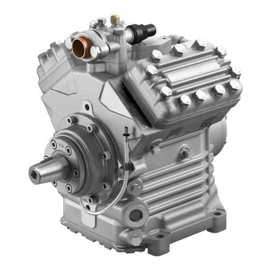
Page 5: Product Description
3 I Product description Product description Series FK40 vehicle compressors are designed for mobile applications. Short description Three design variations are available for different areas of application: > For air conditioning the K design > For air conditioning or normal cooling the N design >... - Page 6 3 I Product description Main and functional parts 1. Discharge shut-off valve 10. Baseplate 2. Cylinder cover 11. Connection thermal protection thermostat 3. Valve plate 12. Oil filling plug 4. Compressor housing 13. Oil sight glasses (2x) 5. Location hole for fitting magnetic coupling 14.
- Page 7 All rights reserved in the event payment of damages. All rights reserved in the event Nein / No GEA Bock GmbH - Benzstraße 7 - 72636 Frickenhausen - Germany - w GEA Bock GmbH - Benzstraße 7 - 72636 F Zust. / Rev.
-
Page 8: Technical Data
4 I Technical data... -
Page 9: Maintenance
It is for this reason, that we only recommend the use of oil from Bock! Bock assumes no liability for any damage arising from alternative oil types. - Page 10 5 I Maintenance Operating of the shut-off valves Position A Opening the shut-off valve: a) Spindle 1: turn to the left (counter-clockwise) as far as it will go. —> Shut-off valve fully opened / service connection 2 closed (position A), Fig. Pipe connection Position B Opening the service connection (2)
-
Page 11: Fault Diagnosis
In order to localize the causes of operating malfunctions as easy as possible we have compiled the following table with suggestion for remedying compressor malfunctions. Further information is retrievable under vap.bock.de (mobile applications -> tools -> online analysis). Additionally a failure analysis slide is obtainable under service@bock.de. - Page 12 6 I Fault diagnosis Problem Possible cause Remedy Cutoff through high pressure Condensing pressure too high: switch - Check the setting of the high-pressure switch - Adjust the switching points or replace switch - Pressure valve of the compressor closed - Open the pressure valve - Condenser fan not functioning - Check the control / replace motor...
- Page 13 6 I Fault diagnosis Refrigerant temperature too high Problem Possible cause Remedy Suction gas temperature - Suction gas overheating - Adjust expansion valve too high Insulate the gas suction line - Too little refrigerant filling - Establish the operating filling (see Operating Instruction for the refrigeration plant), localize leak - Liquid filter blocked...
- Page 14 6 I Fault diagnosis Abnormal running noise from compressor Problem Possible cause Remedy Fixation of compressor is loose - Screwed connections have become loose - Tighten the screwed connections and secure - Securing elements for screwed connections them anew missing - Vibration metals defective - Replace vibrations metals Liquid shock...
-
Page 15: Installation Of Service Kits
Important Notes INFO Use only new gaskets for assembly The following illustrations show a FK40 compressor in standard design. Components of other designs can differ from these illustrations. However, the procedure for disassembly and assembly of the compressor is identical. - Page 16 7 I Installation of service kits Shaft seal (Item No. 80023 (ester oil charge) resp. 80682 (mineral oil charge)) Removal: Dismount the drive/magnetic coupling from the compressor. Remove the woodruff key from seat at the shaft end. Remove the clamping ring (10) and the oil felt (9) (for this see Fig. 3 on page 17). Unscrew the screws (8) from the shaft seal cover (6) .
- Page 17 7 I Installation of service kits Clamping ring with oil felt (Item No. 80129) Procedure: Remove the clamping ring (1) and the oil felt (2) (see Fig. 3) Insert the oil felt (2) included in the repair kit and mount the clamping ring (1).
- Page 18 7 I Installation of service kits Capacity regulation The capacity regulation takes place through the turning off of the suction gas flows by means of a solenoid valve on the cylinder cover. For this, the valve is activated electrically by a thermostat or pressostat. During normal operation the solenoid is de-energized and the suction gas channel in the valve plate and in the cylinder cover is open.
- Page 19 7 I Installation of service kits Valve plate Compressor type Kit (Item No.) Compressor type Kit (Item No.) FK(X)40/390 N 80240 FK(X)40/390 TK 80240 FK(X)40/470 N 80240 FK(X)40/470 TK 80240 FK(X)40/560 N 80241 FK(X)40/560 TK 80241 FK(X)40/655 N 80241 FK(X)40/655 TK 80241 FK(X)40/390 K to FK(X)40/655 K 80010...
- Page 20 7 I Installation of service kits Removal (see Fig. 6): Unscrew the screws (1) from the cylinder cover (2) and dismount cylinder cover (2) with valve plate (4). Remove the gasket residues from the body of the compressor. INFO Don‘t let any gasket residues fall into the compressor Installation (see Fig.
-
Page 21: Electromagnetic Coupling
8 I Electromagnetic coupling Assembly instruction for electromagnetic coupling For the drive of A/C compressors in buses, mainly electromagnetic couplings are used. The followings assembly instructions for coupling type LA 16 is representative for couplings which are mounted onto the front bearing flange of the compressor. Assembly instruction for electromagnetic coupling type LA 16 The front bearing flange has a location face Ø... - Page 22 8 I Electromagnetic coupling INFO Arrange the cable (8) so that it doesn‘t touch hot parts (e.g. protection pipe). = 105°C! Remove the K-circlip (5) and the clamping screw (4) from the rotor assembly (3). Looking through the rotor hole, pay attention to the cor- rect seating of the Woodruff key in the rotor slot.
-
Page 23: Compressor Defects
9 I Compressor defects Compressor defects Compressor defects may have various causes. The table below is meant to aid you while analysing the cause of the breakdown by means of the defective compressor parts found. Thus, the specific remedying of the cause of the breakdown is facilitated. Compressor part Possible causes / Symptom Remedy... -
Page 24: Disassembly Of The Compressor
The disassembly of the compressor is explained in separate steps on the following pages. The indicated parts list positions refer to the spare parts lists, repair set lists, special accessories part lists and are available online at www.vap.bock.de. You can find the exploded drawing at the end of the maintenance manual. - Page 25 10 I Disassembly of the compressor Removal of all shut-off valves and blind flanges Position in Parts list position: 2060, 2070, 232 parts list Tools: Spanner SW 17, allen key 6 mm Working course - The compressor has to be depressurized - Unscrew the fixing screws of shut-off valves 330, 210 - Remove the shut-off valves and the gaskets...
- Page 26 10 I Disassembly of the compressor Removal of the oil filter Position in Parts list position: 2130 parts list Tools: Container > 2 liter for collection oil, spanner SW 19, allen key 10 mm Working course - Drain the oil from the compressor into a suitable container - Unscrew the plug - Remove the gasket - Unscrew the oil filter...
- Page 27 10 I Disassembly of the compressor Removal of the cylinder cover and valve plates Position in parts Parts list position: 170, 2000 (N / TK versions), 1940, 2900 (K version) list Tools: Spanner SW 17 Working course ATTENTION In order to prevent any mix-up during reassembly, mark the cylinder cover and the valve plates belonging together clearly and in a wipe-resistant fashion! N / TK 180, 181...
- Page 28 10 I Disassembly of the compressor Removal of the shaft seal Position in Parts list position: 2010 parts list Tools: Allen key 6 mm Working course INFO For a detailed description for the old version (until version ID 014) see also the section on the removal of the shaft seal on page 16! - Place the oil collection container under the shaft seal area 2110...
- Page 29 10 I Disassembly of the compressor Removal of the oil pump Position in Parts list position: 2020 parts list Tools: Spanner SW 13 Working course 40, 41 - Loosen screws on the oil pump and unscrew 460, 470 - Remove the oil pump and gasket...
- Page 30 10 I Disassembly of the compressor Removal of the baseplate Position in Parts list position: 20, 30, 40 parts list Tools: Container for collection oil, spanner SW 13 Working course - Place the compressor into the oil collection pan and turn it sideways - Unscrew the screws from the baseplate 20, 30 - Remove the baseplate and the gasket...
- Page 31 10 I Disassembly of the compressor Disassembly of the compressor rods from the crankshaft Position in Parts list position: 2040 opt. 2045 or 2030 opt. 2035 together with 2100 parts list Tools: Spanner SW 10 Working course INFO In order to prevent any mix-up during reassembly, mark the connecting rods and caps belonging together clearly and in a wipe-resistant fashion! 2100 - Unscrew the hexagon head screws from the connecting rod cap...
- Page 32 10 I Disassembly of the compressor Removal of the front bearing Position in Parts list position: 2140 parts list Tools: Allen key 6 mm Working course - Loosen the screws at the front bearing and unscrew 730, 740, - Remove the front bearing flange, gasket, and O-ring...
- Page 33 10 I Disassembly of the compressor Removal of the crankshaft Position in Parts list position: 2050 parts list Tools: - Working course 2050 - Pull out the crankshaft carefully in direction of the front bearing flange...
- Page 34 10 I Disassembly of the compressor Remove pistons and connecting rods Position in Parts list position: 2040 opt. 2045 or 2030 opt. 2035 together with 2100 parts list Tools: Needle-nosed pliers Working course - Mark corresponding pistons of cylinder bore 2100, 2030 - Remove the piston / connecting rod in direction of baseplate - Remove circlips of the piston pins with needle-nosed pliers...
- Page 35 Parts list position: - parts list Tools: Spanner SW 13, 14, 30 or 36. For the decompression valve: Bock special tool item No. 09524 (up to A015*), socket wrench SW 22 (from A017*) Working course - Dismount the sight glass - Remove O-ring - Remove the 1/8‘‘...
- Page 36 10 I Disassembly of the compressor Removal of the roller bearings Position in Parts list position: 2150 parts list Tools: Pulling apparatus Working course 2150, 730 - With the pulling apparatus pull out the roller bearing from the front bearing flange INFO Use oil, if necessary! If a pulling apparatus is not available, the front bearing flange may be heated for approx.
-
Page 37: Checking The Compressor Parts
11 I Checking the compressor parts Checking compressor parts for damages and wear Before re-using removed compressor parts we recommend that they be checked for usability. The wear limits listed below should be taken into consideration: Piston - cylinder bore 0.13 mm Connecting rod - piston pin 0.03 mm Crankshaft - connecting rod 0.08 mm... - Page 38 11 I Checking the compressor parts Pistons There should be no visible damages on the piston crown and the piston walls. The grooves for the piston rings must be clean and undamaged. Check the condition of the piston rings for wear, fractures and other irregularities.
- Page 39 If necessary, the filter have to be cleaned with compressed air or replaced with new ones. Internal decompression valve (use Bock special tool item No. 09524 up to A015, socket wrench SW 22 from A017). The internal decompression valve must be replaced after it has operated.
-
Page 40: Assembly Of Compressor
12 I Assembly of compressor Fitting the roller bearings Position in Parts list position: 2150 parts list Tools: Pressing apparatus Working course - Heat the bearing flange / compressor casing for approx. 20 minutes in a pre-heated (120°C) baking oven - Insert tolerance ring into the roller bearing, if available 2150 - Press the roller bearings onto the compressor casing and the front bearing flange... - Page 41 Fitting the sight glass, plugs and decompression valve Position in Parts list position: - parts list Tools: Spanner SW 13, 14, 30 or 36. For the decompression valve: Bock special tool item No. 09524 (up to A015), socket wrench SW 22 (from A017) Working course INFO...
- Page 42 12 I Assembly of compressor Assembly of the pistons / connecting rods Position in Parts list position: 2040 opt. 2045 or 2030 opt. 2035 together with 2100 parts list Tools: Needle-nosed pliers Working course - Assemble piston and connecting rod with piston pin, use some oil for easier assembly - Mount circlips with pliers on both sides of the piston pins...
- Page 43 12 I Assembly of compressor Fitting the piston / connecting rods Position in Parts list position: 2040 opt. 2045 or 2030 opt. 2035 together with 2100 parts list Tools: Spanner SW 10, piston ring pliers Working course We recommend, cleaning the housing from the inside before assembly 2100 - Remove the connecting rod cap from the preassembled connecting rod assembly and mark it - Apply a little oil to the cylinder bore...
- Page 44 12 I Assembly of compressor Fitting the crankshaft Position in Parts list position: 2050 parts list Tools: - Working course 2050 - Fit the crankshaft so that the drive journal engages into the pump gear - Apply bearing position with oil...
- Page 45 12 I Assembly of compressor Installation of the front bearing flange Position in Parts list position: 2140, 2120 parts list Tools: Allen key 6 mm Working course INFO Observe the tightening torques! - Apply oil to the O-ring and place it into the groove in the bearing flange - The sealing surfaces have to be clean.
- Page 46 12 I Assembly of compressor Assembly of the inserted connecting rods and pistons Position in Parts list position: 2040 opt. 2045 or 2030 opt. 2035 together with 2100 parts list Tools: Piston ring pliers, spanner SW 10 Working course INFO Pay attention to the correct pairing of connecting rods and connecting rod caps! Replace connecting rod cap screws or in the case of reusing put on a sticker! - Compress the oil scraper ring and compression ring with the piston ring pliers and insert the piston into the...
- Page 47 12 I Assembly of compressor Install of the oil pump Position in Parts list position: 2020 parts list Tools: Spanner SW 13 Working course INFO Observe the tightening torques! Pay attention to the tightening sequence of the screws! - The sealing surfaces have to be clean. Slightly oil seals 40, 41 - Install the oil pump with gasket into the body with the inscription „TOP“...
- Page 48 Position in Parts list position: 2010 parts list Tools: Allen key 6 mm, brush Working course GEA Bock GmbH Benzstraße 7, 72636 Frickenhausen, Germany INFO Caution! Avoid damages! Pay attention to the markings! Phone: +49 7022 9454-0, Fax: +49 7022 9454-137 Be sure to observe the detailed working steps illustrated below! info@gea.com, www.gea.com...
- Page 49 Fitting the shaft seal 6 mm CLICK...
- Page 50 Fitting the shaft seal 6 mm - 37 Nm...
- Page 51 12 I Assembly of compressor Installation of the baseplate Position in Parts list position: 20, 30, 40 parts list Tools: Spanner SW 13 Working course INFO Observe the tightening torques! Pay attention to the tightening sequence of the screws! - Install the baseplate with gasket 20, 30 - Tighten the screws (M8x30) crosswise 34 Nm...
- Page 52 12 I Assembly of compressor Installation of the oil filter Position in Parts list position: 2130 parts list Tools: Allen key 10 mm, spanner SW 19 Working course INFO Observe the tightening torques! - With the allen key, screw on the filter into the hole in the body and tighten it - Install gasket - Screw on the M22x1.5 mm plug and tighten it 100 Nm...
- Page 53 12 I Assembly of compressor Installation of the cylinder covers and valve plates Position in parts Parts list position: 170, 2000 (N / TK versions), 1940, 2900 (K version) list Tools: Spanner SW 17 Working course ATTENTION Install only the cylinder covers and valve plates which belong together, avoid mix-ups! Observe the tightening torques! N / TK 60, 50...
- Page 54 12 I Assembly of compressor Installation of all shut-off valves and blind flanges Position in Parts list position: 2060, 2070, 232 parts list Tools: Spanner SW 17, allen key 6 mm Working course INFO Observe tightening torques! Use screws of correct length for the installation of the intermediate flanges! - Put in the suction filter with the gasket 230, 210 - Install the shut-off valves (on the discharge and suction side) with gaskets and screws...
- Page 55 Remark: If the compressor is going to remain in the warehouse, charge it with nitrogen (at about 3 bar pressure) for protection. ATTENTION Take the reminders for commissioning in the assembly instruction for FK40 into account! Torques for screwed connections...
-
Page 56: Spar Parts List
You can order individual items listed in this maintenance manual, with the corresponding item number, simply via our spare parts lists. You can view these at any time via our Bock compressor selection programme „VAP“ (vap.bock. de) or our spare parts catalogue BOCK shop (bockshop.bock.de). -
Page 57: Exploded Drawing
14 I Exploded drawing... - Page 58 BOCK ® Bock GmbH Benzstraße 7 72636 Frickenhausen Deutschland Tel +49 7022 9454-0 Fax +49 7022 9454-137 www.bock.de © Bock GmbH. All rights reserved. Subject to modifications. Printed in Germany.
Need help?
Do you have a question about the FK40 and is the answer not in the manual?
Questions and answers