Table of Contents
Advertisement
Quick Links
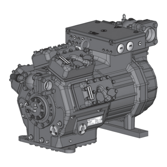
Reciprocating Compressor
BOCK UL-HGX88e
Assembly instructions
(Translation of the original instructions)
96719-01.2024-Us
UL-HGX88e/2400 ML 60
UL-HGX88e/2735 ML 70
UL-HGX88e/3235 ML 80
Bock GmbH, Benzstr. 7, 72636 Frickenhausen, Germany
Phone: +49 7022 9454-0, Fax: +49 7022 9454-137
www.bock.de, service@bock.de
BOCK
®
UL-HGX88e/2400 S 70
UL-HGX88e/2735 S 80
UL-HGX88e/3235 S 95
colour the world
of tomorrow
Advertisement
Table of Contents

Related Manuals for BOCK UL-HGX88e/2400 ML 60


Summary of Contents for BOCK UL-HGX88e/2400 ML 60
- Page 1 UL-HGX88e/2400 ML 60 UL-HGX88e/2400 S 70 UL-HGX88e/2735 ML 70 UL-HGX88e/2735 S 80 UL-HGX88e/3235 ML 80 UL-HGX88e/3235 S 95 Bock GmbH, Benzstr. 7, 72636 Frickenhausen, Germany Phone: +49 7022 9454-0, Fax: +49 7022 9454-137 www.bock.de, service@bock.de BOCK ® colour the world...
-
Page 2: Table Of Contents
It must be passed onto the end customer along with the unit in which the compressor is installed. This document is subject to the copyright of BOCK GmbH, Germany. The information provided in this manual is subject to change and improvements without notice. - Page 3 Contents Page Compressor assembly ..................... 9 Storage and transport ......................9 Setting up .......................... 9 Pipe connections ......................10 Pipes ..........................10 Starting unloader (external) ..................... 10 Laying suction and pressure lines ..................11 Operating the shut-off valves ................... 12 Operating mode of the lockable service connections ............
-
Page 4: Safety
1| Safety Identification of safety instructions Indicates a dangerous situation which, if not avoided, will cause immediate fatal or serious injury. Indicates a dangerous situation which, if not avoided, may cause fatal or serious injury. Indicates a dangerous situation which, if not avoided, may cause fairly severe or minor injury. -
Page 5: Intended Use
These assembly instructions describe the standard version of the compressor named in the title manufactured by Bock. Bock refrigerating compressors are intended for installation in a ma- chine (within the EU according to the EU Directives 2006/42/EC Machinery Directive, 2014/68/ EU Pressure Equipment Directive, outside the EU according to the respective national regulations and guidelines). -
Page 6: Product Description
2 | Product description 2.1 Short description • Semi-hermetic eight-cylinder reciprocating compressor with suction-gas cooled drive motor. • The stream of refrigerant sucked out of the evaporator flows over the motor and cools it intensively. In this way, the motor can be kept at a relatively low temperature level, particularly under high loads. -
Page 7: Name Plate (Example)
2 | Product description 2.2 Name plate (example) BOCK Bock GmbH, Benzstr. 7 72636 Frickenhausen, Germany thermally protected system Y/YY UL-HGX88e/3235 S 95 AW09529A047 9936 cfh Y/YY 162,0 A 11923 cfh Y: 466 A YY: 657 A LP/HP = 276/406 psig... -
Page 8: Areas Of Application
More informations about approved refrigerants on Bock compressor selection tool VAP (vap.bock.de). 3.2 Oil charge The compressors are filled at the factory with the following oil type: BOCK lub E55 For refilling, we recommend the above oil types. See also section 7.4. -
Page 9: Compressor Assembly
3 | Areas of application Maximum admissible frequency: 60 Hz Maximum admissible operating pressure (LP/HP) LP = Low pressure 19/28 barg (276/406 psig) HP = High pressure 4 | Compressor assembly New compressors are factory-filled with inert gas. Leave this service charge in the compressor for as long as possible and pre- vent the ingress of air. -
Page 10: Pipe Connections
4 | Compressor assembly 4.3 Pipe connections Damage possible. Do not solder as long as the compressor is under pressure. Superheating can damage the valve. Remove the pipe supports therefore from the valve for soldering and accordingly cool the valve body during and after soldering. Only solder using inert gas to inhibit oxidation products (scale). -
Page 11: Laying Suction And Pressure Lines
4 | Compressor assembly Solenoid valve dead Non-return valve open Fig. 6 Important: Starting unloader may only be employed during the starting phase. Check the solenoid valve and the non-return valve regularly for tightness. In addition, we recommend using a heat protection thermostat on the discharge side of the com- pressor. -
Page 12: Operating The Shut-Off Valves
4 | Compressor assembly 4.7 Operating the shut-off valves Before opening or closing the shut-off valve, release the valve spindle seal by approx. 1 / 4 of a turn counter-clockwise. After activating the shut-off valve, re-tighten the adjustable valve spindle seal clockwise. Release Tighten Valve spindle seal... -
Page 13: Suction Pipe Filter And Filter Drier
4 | Compressor assembly 4.9 Suction pipe filter and filter drier For systems with long pipes and higher degree of contamination, a filter on the suction-side is recommended. The filter has to be be renewed depending on the degree of contamination (reduced pressure loss). -
Page 14: Standard Motor, Design For Direct Or Partial Winding Start
5 | Electrical connection 5.3 Standard motor, design for direct or partial winding start Designation on the name plate Y/YY Compressors with this marking are suitable for direct or partial winding start. The motor winding is subdivided into two parts: Part winding 1 = 50 % and part winding 2 = 50 %. - Page 15 nmotor für Direkt- oder Teilwicklungsstart Typschildangabe Gelber Aufkleber ührung für Direkt- oder Teilwicklungsstart t dieser Kennzeichnung ist für Direkt- Typschildangabe Gelber Aufkleber am Klemmenkasten chter mit dieser Kennzeichnung ist für Direkt- klungsstart (PW-Anlauf) geeignet. am Klemmenkasten 5 | Electrical connection ∆/YYY Teilwicklungsstart (PW-Anlauf) geeignet.
-
Page 16: Basic Circuit Diagram For Part Winding Start With Standard Motor
5.4 Circuit diagram for part winding start FC1.2 FC1.1 I> I> I> I> I> I> FC1.1 FC1.2 L3 N PE Y/YY B1 B2 INT69 Anschlußkasten Verdichter Compressor terminal box Fig. 12 High pressure safety monitor Safety chain (high/low pressure monitoring) Cold conductor (PTC sensor) motor winding Thermal protection thermostat Oil temperature sensor (PTC sensor) - Page 17 FC1.1/1.2 Motor protection switch Control power circuit fuse INT69 G Electronic trigger unit INT69 G Delay relay for contactor switch over Main switch Mains contactor (part winding 1) Mains contactor (part winding 2) PW INT69 HG88 Control voltage switch BOCK COMPRESSORS...
-
Page 18: Special Motor: Design For Direct Or Star-Delta Start
5 | Electrical connection 5.5 Special motor: design for direct or star-delta start A mechanical unloaded start with bypass solenoid valve (accessories) is required for the star-delta start. Designation on the name plate ∆ / Y... - Page 19 5 | Electrical connection ∆ Star-delta start-up is only possible for power supply. Example: ∆ lower voltage higher voltage Y Direct start only Direct start Star-delta-start In the factory the motor is wired for direct starting at high voltage. The brides are to be removed for star delta starting at low voltage.
-
Page 20: Circuit Diagram For Star-Delta Start 230 V ∆ / 400 V Y
5.6 Circuit diagram for star-delta start FC1.1 I> I> I> FC1.1 FC1.2 FC1.2 I> I> I> L3 N PE ˜ B1 B2 INT69G Compressor terminal box Anschlußkasten Verdichter Fig. 13 High pressure safety monitor Safety chain (high/low pressure monitoring) Cold conductor (PTC sensor) motor winding Thermal protection thermostat Oil temperature sensor (PTC sensor) Release switch (thermostat) - Page 21 Θ Θ DELTA- P II FC1.1/1.2 Motor protection switch Control power circuit fuse INT69 G Electronic trigger unit INT69 G Delay relay for contactor switch over Main switch Mains contactor D/S INT69 HG88 Δ-contactor Y-contactor BOCK COMPRESSORS Control voltage switch...
-
Page 22: Electronic Trigger Unit Int69 G
5 | Electrical connection 5.7 Electronic trigger unit INT69 G The compressor motor is fitted with cold conductor temperature sensors (PTC) connected to the electronic trigger unit INT69 G in the terminal box. In case of excess temperature in the motor winding, the INT 69 G deactivates the motor contactor. -
Page 23: Function Test Of The Trigger Unit Int69 G
5 | Electrical connection 5.9 Function test of the trigger unit INT69 G Before commissioning, after troubleshooting or making changes to the control power circuit, check the functionality of the trigger unit. Perform this check using a continuity tester or gauge. Relay position INT69 G Gauge state Relay position... -
Page 24: Capacity Regulator (Accessories)
5 | Electrical connection 5.11 Capacity regulator (accessories) A fuse (max. 3xlB in accordance with IEC 60127-2-1) corresponding to the rated current must be placed in front of every magnetic coil of the capacity regulator as short-circuit protection. The ra- ted voltage of the fuse must be equal to or greater than the rated voltage of the magnetic coil. -
Page 25: Commissioning
6 | Commissioning 6.1 Preparations for start-up To protect the compressor against inadmissible operating conditions, high pressure and low pressure pressostats are mandatory on the installation side. The compressor has undergone trials in the factory and all functions have been tested. There are therefore no special running-in instructions. -
Page 26: Refrigerant Charge
6 | Commissioning 6.5 Refrigerant charge Wear personal protective clothing such as goggles and protective gloves! Make sure that the suction and pressure line shut-off valves are open. With the compressor switched off, add the liquid refrigerant directly to the condenser or receiver, breaking the vacuum. -
Page 27: Maintenance
It is for this reason, that we only recommend the use of oil from Bock! Bock assumes no liability for any damage arising from alternative oil types. -
Page 28: Accessories
8 | Accessories 8.1 Capacity regulator If the capacity regulator is installed at the factory, the control component (pilot valve) is subsequently installed and connected by the customer. LR 1 LR 2 LR 3 Delivery condition 1 (from the factory): Fig. -
Page 29: Oil Separator
Information about the use, operation, maintenance and servicing of the components is available in the printed literature or on the internet under vap.bock.de. 8.2 Oil separator Oil slugging can result in damage to the compressor. -
Page 30: Oil Level Regulator
8 | Accessories 8.3 Oil level regulator Oil level regulation systems have proven themselves with parallel circuits of several compressors. The connection "0" is provided for installing an oil level regulator (see dimensions drawing). All common mechanical oil level regulators from AC&R, ESK, Carly as well as the electronic oil level regulation system from AC&R, Teklab, OM3 TraxOil from Alco and ESK (only long version) can be connected directly without adapters (see fig.21). -
Page 31: Technical Data
9 | Technical data Oil charge (sight glass centre) Oil charge (ex works) Suction line Discharge line Weight Adjustable 25 - 60 frequency range Starting current (rotor locked) Max. power consumption Max. operating current 380-420 V Y/YY - 3 - 50 Hz PW 440-480 V Y/YY - 3 - 60 Hz PW Voltage PW = Part Winding... -
Page 32: Dimensions And Connections
HG(X)88e/2400-4 14256 (14258) HG88e/2400-4 HC 14010 HGX88e/2400 ML 60 LG 14654 UL-HGX88e/2400 ML 60 16612 HG(X)88e/2400-4 S 14257 (14259) HG88e/2400-4 S HC 14011 HGX88e/2400 S 70 LG 14655 UL-HGX88e/2400 S 70 16613 1.085 HG(X)88e/2735-4 14292 (14296) HG88e/2735-4 HC... - Page 33 10 | Dimensions and connections Suction line see technical data, Chapter 9 Discharge line Connection suction side, , not lockable 8 “ NPTF Connection suction side, , lockable 16 “ UNF Connection suction side, , not lockable 4 “ NPTF Connection discharge side , not lockable 8 “...
-
Page 34: Declaration Of Incorporation
11 | Declaration of incorporation ® Declaration of incorporation for incomplete machinery in accordance with EC Machinery Directive 2006/42/EC, Annex II 1. B Manufacturer: Bock GmbH Benzstraße 7 72636 Frickenhausen, Germany We, as manufacturer, declare in sole responsibility that the incomplete machinery Name:... - Page 35 Declaration of incorporation of partly completed machinery in accordance with UK Statutory Instrument Supply of Machinery (Safety) Regulations 2008, Annex II 1. B Manufacturer: Bock GmbH Benzstraße 7 72636 Frickenhausen, Germany We, as manufacturer, declare in sole responsibility that the partly completed machinery...
-
Page 36: Ul-Certificate Of Compliance
12| UL-Certificate of Compliance Dear customer, the Certificate of Compliance can be downloaded by the following QR-Code: https://vap.bock.de/stationaryapplication/Data/ DocumentationFiles/UL-Certificateofconformity.pdf... -
Page 37: Service
Dear customer, if you have any questions about installation, operation and accessories, please contact our technical service or specialist wholesaler and/or our representative. The Bock service team can be contacted by phone, +49 (0)7022 9454-0 or via service@bock.de Yours faithfully Bock GmbH... - Page 38 BOCK ® Bock GmbH Benzstraße 7 72636 Frickenhausen Germany Phone +49 7022 9454-0 +49 7022 9454-137 www.bock.de © Bock GmbH. All rights reserved. Subject to modifications.
Need help?
Do you have a question about the UL-HGX88e/2400 ML 60 and is the answer not in the manual?
Questions and answers