Advertisement
Quick Links
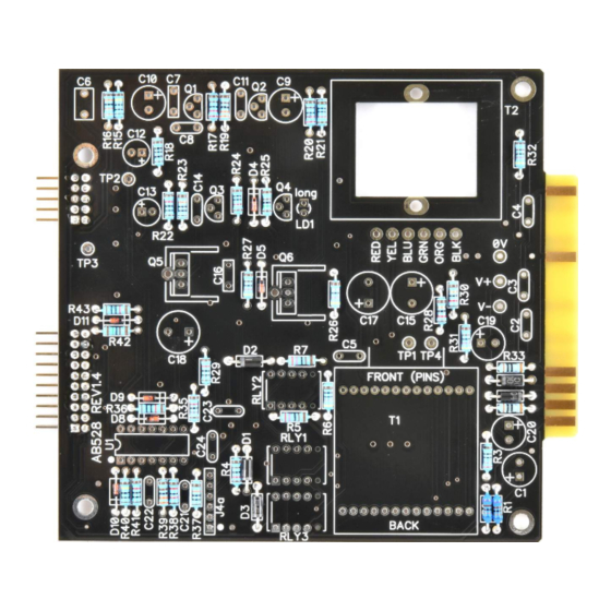
AB528 Assembly guide
Safety warning
The kits are main powered and use potentially lethal voltages. Under no circumstance should someone undertake the
realisation of a kit unless he has full knowledge about safely handling main powered devices.
Please read the "DIY guide" before beginning.
Print or open the following documents:
• AB528 Schematics
• AB528 Components layout
• AB528 Parts list
Follow this guide from item number 1 till the end, in this order. The assembly order is based on components height, from
low to high profile, in order to ease the soldering process : The component you are soldering is always taller than the
previously assembled ones and it is pressing nicely against the work area foam.
Soldering
All the PCB holes are metallized. It means the connections between the top and bottom pads are already
made. The parts must be soldered only from below (unless differently stated).
Use only small diameter solder, 0.5 or 0.7 mm, 1mm maximum. Use the minimum possible amount of
solder. Bad joints are almost always caused by too much solder.
If ever, because you have made a mistake, you need to remove a component, DO NOT TRY TO SAVE IT!
Instead, cut the pins and remove them one by one. Because this PCB is made of 4 layers and there is a
very high risk of breaking the connections between layers if you force a lead out.
Here are two excellent introduction to soldering videos:
http://www.eevblog.com/2011/06/19/eevblog-180-soldering-tutorial-part-1-tools/
http://www.eevblog.com/2011/07/02/eevblog-183-soldering-tutorial-part-2/
In case of error: component soldered in the wrong place
Do not try to save the component! This will very likely damage the PCB which cost 100 times more than
most components.
Except for transformers which are also expensive, cut the components pins with cutting pliers in order to
be able to remove the pins one by one.
Then empty the holes with a de-soldering pump (this one works great : Jonard Industries DP-100).
Copyright ©2022 to today SoundSkulptor
Document revision 1.1 – Last modification : 11/15/22
www.soundskulptor.com
Advertisement

Related Manuals for Sound Skulptor AB528


Summary of Contents for Sound Skulptor AB528
- Page 1 Please read the “DIY guide” before beginning. Print or open the following documents: • AB528 Schematics • AB528 Components layout • AB528 Parts list Follow this guide from item number 1 till the end, in this order. The assembly order is based on components height, from low to high profile, in order to ease the soldering process : The component you are soldering is always taller than the previously assembled ones and it is pressing nicely against the work area foam.
- Page 2 Document revision 1.1 – Last modification : 11/15/22 AB528 Assembly guide – Main PCB PCB split Split the PCB into 6 parts along the grooves and mouse bites. Use extra thin sandpaper to polish all the rough sides. Connector J1a and J2a Insert the male 2x10 and 2x5 pins connectors into their place at the back of the main PCB.
-
Page 3: Ceramic Capacitors
Document revision 1.1 – Last modification : 11/15/22 AB528 Assembly guide – Main PCB Ceramic capacitors Add the ceramic capacitors. Red LED Insert and solder the red LED LD1. Warning: The longest lead goes into the top hole marked “long”. - Page 4 Document revision 1.1 – Last modification : 11/15/22 AB528 Assembly guide – Main PCB Test pins Solder the 7 test pins TP1, TP2, TP3, TP4, 0V, V+, V-. 10. Film capacitors Add the film capacitors C7, C16, C6. 11. Transistors Add Q1, Q3 and Q2, Q4.
- Page 5 Document revision 1.1 – Last modification : 11/15/22 AB528 Assembly guide – Main PCB 13. Small electrolytic capacitors Add the electrolytic capacitors C12, C13, C9, C10, C19, C20, C1. Warning : The +lead must go into the +hole. Do not reverse (they may explode!) 14.
- Page 6 Document revision 1.1 – Last modification : 11/15/22 AB528 Assembly guide – Main PCB 16. Transformer T1 front PCB Use the input transformer front PCB, the one with the pin holes and numbers. Insert the 90°, 13 pins headers, long tails first, into the holes, from the bottom side, marked “Not visible”.
- Page 7 Document revision 1.1 – Last modification : 11/15/22 AB528 Assembly guide – Main PCB 21. U1 Insert U1 into its socket. Warning : The correct direction is identified by a notch or a dot. 22. Visual check Check that all component leads are cut short, in order not to risk touching the chassis plate. Brush the solder side with a hard tooth brush to remove any remaining solder bits.
- Page 8 Document revision 1.1 – Last modification : 11/15/22 AB528 Assembly guide – Front PCB 24. Connectors J1b, J2b Insert the 2x5 and 2x10 female connectors at the back of the PCB and solder on the components side. 25. Toggle switches Add the toggle switches SW1, SW2, SW4.
- Page 9 Document revision 1.1 – Last modification : 11/15/22 AB528 Assembly guide – Front PCB 29. LED Insert the LED LD2, taking care of the anode/cathode (long/short lead) position. Do not solder yet. Attach the PCB to the front panel with 3 M2.5x6mm black screws.
- Page 10 Insert U2 into its socket. Warning : The correct direction is identified by a notch or a dot. AB528 Assembly guide – Final assembly Chassis plate assembly Attach the chassis plate to the front plate with two M3x6mm black screws.
- Page 11 Document revision 1.1 – Last modification : 11/15/22 AB528 Assembly guide – Final assembly 13. Knobs Attach the 2 knobs. 14. Cover Attach the cover with 4 M3x6mm countersunk screws. 15. Congratulations You're done! Copyright ©2022 to today SoundSkulptor...
Need help?
Do you have a question about the AB528 and is the answer not in the manual?
Questions and answers