Table of Contents
Advertisement
Quick Links
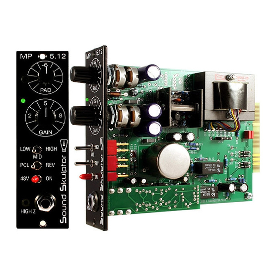
MP 5.12 Assembly guide
Safety warning
The kits are main powered and use potentially lethal voltages. Under no circumstance should someone undertake the
realisation of a kit unless he has full knowledge about safely handling main powered devices.
Please read the "DIY guide" before beginning.
Print or open the following documents :
• MP512 Schematics
• MP512 Components layout
• MP512 Parts list
• MP512 Test guide
Follow this guide from item number 1 till the end, in this order. The assembly order is based on components height, from
low to high profile, in order to ease the soldering process : The component you are soldering is always taller than the
previously assembled ones and it is pressing nicely against the work area foam.
MP 5.12 Assembly guide
1.
DOA Pin Sockets
Solder the 7 pin sockets for the DOA. Solder one at a time. Insert one
socket, turn over the PCB and press against a solid but flexible surface like
cork or dense foam then solder. The correct positioning of the sockets is
very important for easy insertion of the DOA.
2.
Add D1 to D4, D6 to D11. Use a lead forming tool to bend the leads at 0.4".
Warning
: Make sure to respect the direction of the diodes which is marked by a ring on the component
and a double line on the PCB marking.
3.
Add R1 to R40. The resistors marked NC in the parts-list should not be installed.
Control the resistor values with a digital multimeter. Bend the leads at 0.4" with a lead forming tool.
4.
Integrated Circuit
Insert U2 and solder. You will need to bend the pins slightly inwards before inserting. Make sure you are
not charged with electrostatic electricity before handling the IC (or remove your shoes).
Warning
: Make sure to respect the IC direction, marked by a notch. Do not use a socket because it
would be to high for the Di01 board.
5.
Inductor
Add L1. Bend at 0.8".
Copyright ©2013 SoundSkulptor
Document revision 1.1 – Last modification : 15/07/20
www.soundskulptor.com
Advertisement
Table of Contents

Related Manuals for Sound Skulptor MP 5.12


Summary of Contents for Sound Skulptor MP 5.12
- Page 1 Document revision 1.1 – Last modification : 15/07/20 MP 5.12 Assembly guide Safety warning The kits are main powered and use potentially lethal voltages. Under no circumstance should someone undertake the realisation of a kit unless he has full knowledge about safely handling main powered devices.
- Page 2 Document revision 1.1 – Last modification : 15/07/20 MP 5.12 Assembly guide Bend the leads of D5 right angle at 6mm from the body taking care of the anode position (the longest lead).Insert from the PCB bottom and solder with the LED body lined up with the PCB surface.
- Page 3 Document revision 1.1 – Last modification : 15/07/20 MP 5.12 Assembly guide 12. Relay Add RLY1 and RLY2. 13. Small electrolytic capacitors Add C3, C4, C12, C13, C21, C22, C23. Solder one lead first, adjust verticality then solder the second lead.
- Page 4 Document revision 1.1 – Last modification : 15/07/20 MP 5.12 Assembly guide 15. Potentiometers P1 & P3 Place the bracket on the potentiometer bush. Do not insert the nut yet. Insert potentiometer and bracket into the PCB holes. Solder the 2 central potentiometer pins, taking care that it sits perfectly flat on the PCB.
- Page 5 Document revision 1.1 – Last modification : 15/07/20 MP 5.12 Assembly guide 20. Visual check At this point, brush the solder side with a hard tooth brush to remove any remaining solder bits. Make a full visual check. Any missing component on the board ? Any remaining component in the box ? When everything looks correct, proceed with the frame assembly.
- Page 6 MP 5.12 Assembly guide 23. Knobs Attach the 2 knobs. 24. Test Your MP 5.12 is now ready for test. Please follow instructions in the “MP512 Test” document. Di01 Assembly guide Print or open the following documents : • Di01 Schematics •...
- Page 7 www.soundskulptor.com Document revision 1.1 – Last modification : 15/07/20 Di01 Assembly guide Diodes Add D1, D2 and D3. Use a lead forming tool to bend the leads at 0.4”. Warning : Make sure to respect the direction of the diodes which is marked by a ring on the component and a double line on the PCB marking.
- Page 8 www.soundskulptor.com Document revision 1.1 – Last modification : 15/07/20 Di01 Assembly guide Board installation Place one 1.2mm plastic spacer on the jack sockets and insert into the front panel while fitting the CN2 connector pins into the socket on the preamp PCB. Screw in the front nut through the bevelled front spacer with an M12 socket spanner.
Need help?
Do you have a question about the MP 5.12 and is the answer not in the manual?
Questions and answers