Advertisement
Quick Links
MP 599 Assembly guide
Safety warning
The kits are main powered and use potentially lethal voltages. Under no circumstance should someone undertake the
realisation of a kit unless he has full knowledge about safely handling main powered devices.
Please read the "DIY guide" before beginning.
Print or open the following documents :
• MP599 Schematics
• MP599 Components layout
• MP599 Parts list
• MP599 Test guide
Follow this guide from item number 1 till the end, in this order. The assembly order is based on components height, from
low to high profile, in order to ease the soldering process : The component you are soldering is always taller than the
previously assembled ones and it is pressing nicely against the work area foam.
Soldering
All the PCB holes are metallized. It means the connection between the top and bottom pads is already
done. The parts must be soldered only from below (unless differently stated).
Use only small diameter solder, 0.5 or 0.7 mm, 1mm maximum. Use the minimum possible amount of
solder. Bad joints are almost always caused by too much solder.
Cut the component leads and pins totally flush with the PCB after soldering. A too long tail could create
an electric connection with the side plate.
Here are two excellent introduction to soldering videos:
http://www.eevblog.com/2011/06/19/eevblog-180-soldering-tutorial-part-1-tools/
http://www.eevblog.com/2011/07/02/eevblog-183-soldering-tutorial-part-2/
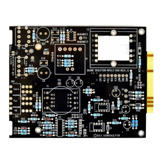
MP 599 Main board Assembly guide
1.
PCB split
Split the PCB into 3 parts along the
grooves (red lines on the picture).
Use extra thin sandpaper to polish
all the rough sides.
2.
DOA Pin Sockets
Solder the 7 pin sockets for the DOA. Solder one at a time.
Depending on the tin thickness on the PCB you may have to press
quite hard to fit them into their hole.
The correct positioning of the sockets is important for easy
insertion of the DOA.
Copyright ©2013 SoundSkulptor
Document revision 2.1 – Last modification : 01/12/21
www.soundskulptor.com
Advertisement

Related Manuals for Sound Skulptor MP 599


Summary of Contents for Sound Skulptor MP 599
- Page 1 Here are two excellent introduction to soldering videos: http://www.eevblog.com/2011/06/19/eevblog-180-soldering-tutorial-part-1-tools/ http://www.eevblog.com/2011/07/02/eevblog-183-soldering-tutorial-part-2/ MP 599 Main board Assembly guide PCB split Split the PCB into 3 parts along the grooves (red lines on the picture). Use extra thin sandpaper to polish all the rough sides.
- Page 2 Document revision 2.1 – Last modification : 01/12/21 MP 599 Main board Assembly guide Diodes Add D1 to D6, D8, D9. Use a lead forming tool to bend the leads at 0.4”. Warning : Make sure to respect the direction of the diodes which is marked by a ring on the component and a double line on the PCB marking.
-
Page 3: Integrated Circuit
Document revision 2.1 – Last modification : 01/12/21 MP 599 Main board Assembly guide Bend the leads of D7 right angle at 6mm from the body taking care of the anode position (the longest lead).Insert from the PCB bottom and solder with the LED body lined up with the PCB surface. - Page 4 Document revision 2.1 – Last modification : 01/12/21 MP 599 Main board Assembly guide 14. Inductor Add L1. This inductor is installed vertically. 15. Small electrolytic capacitors Add C4, C6, C7, C20, C21. Solder one lead first, adjust verticality then solder the second lead.
- Page 5 Document revision 2.1 – Last modification : 01/12/21 MP 599 Main board Assembly guide 18. Output transformer Insert and solder the output transformer. 19. Potentiometers P1 & P2 Place the bracket on the potentiometer bushing, and attach it with the lock washer and nut. Tighten.
- Page 6 Attach the PCB with 4 M3x25 mm spacers and 4 shake-proof washers. 25. Knobs Attach the 2 knobs. 26. Test Your MP 599 is now ready for test. Please follow instructions in the “MP599 Test” document. DI board Assembly guide Horizontal resistors Add R41 to R45, R48 to R51.
-
Page 7: Electrolytic Capacitors
www.soundskulptor.com Document revision 2.1 – Last modification : 01/12/21 DI board Assembly guide Vertical resistors Add R46 & R47. Film capacitor Add C22. Transistors Add Q1 and Q2. The PCB has provision for two pinouts for Q2. With the current 2SK170, use the A position. Warning: Q1 (2N7000) is a device that is sensitive to static electricity before being soldered. - Page 8 www.soundskulptor.com Document revision 2.1 – Last modification : 01/12/21 Final assembly 10. DI bBoard installation Place one 1.2mm plastic spacer on the jack sockets and insert into the front panel while fitting the CN2 connector pins into the socket on the preamp PCB. Screw in the front nut through the beveled front spacer with an M12 socket spanner.
- Page 9 www.soundskulptor.com Document revision 2.1 – Last modification : 01/12/21 Final assembly Copyright ©2013 SoundSkulptor...
Need help?
Do you have a question about the MP 599 and is the answer not in the manual?
Questions and answers