Table of Contents
Advertisement
Quick Links
Follow the testing procedure in the shown order. If one test fails, find out the problem, correct it then resume.
Always unplug power between steps because it is very easy to create a shortcut when moving a DMM probe. And most
of the time, shortcuts are fatal to the circuits.
Step
1.
Short circuit check
2.
Test setup
3.
General power check
4.
Voltage setup
5.
Bias adjust
Copyright ©2007 SoundSkulptor
MP73 Setup guide
Description
Do a basic short circuit check with your digital multimeter (DMM) set to Ohms between
Test point TP4 (GND) and TP3 (V+).
You should get a value greater than a kilo-Ohm. If it is not the case, find out and fix the
short before applying power.
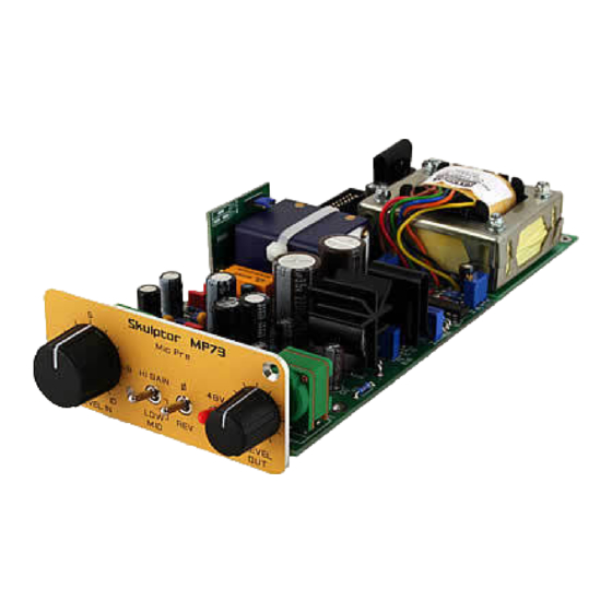
At this point, you need an assembled and wired SKMP case.
Install your MP73 in a free slot. Connect a ribbon to the MP73 board (look at the "SKMP
assembly guide").
Disconnect all other mic pre's by removing their ribbon cable.
Connect the power supply leaving the mains plug disconnected.
Turn trimmer P7 anti-clockwise all the way down (25 turns).
Turn trimmer P6 clockwise all the way up (25 turns).
Warning
: Be very careful when pre-positioning P6 and P7. Doing it the wrong way round
will surely smoke several components !
Plug in power and check that the 3 LEDs on the PSL1 or PSL2 are lighting normally. If one
LED is staying off or is lighting too low or too bright, immediately plug off power and
start checking your board.
Plug off power.
Set your DMM to DC Volts on a 30 V scale and connect it between TP4 (GND) and TP3
(V+). Use test hooks and be careful not to create shortcuts.
Plug in power. Check that you get a positive voltage and that it changes when you turn
P7. Adjust to 24V. Plug off power.
Warning
: Do not confuse P6 (Bias) and P7 (V+ adjust).
With P6, we are going to adjust the
biasing of Q10 in order to flow a 70mA
direct current in the output transformer
primary. To do this, we are going to
measure the voltage between the +24V
point and the collector of Q10.
Set your DMM to DC volts.
Place the (+) probe of your DMM on the
test pin TP3 (V+). Place the (-) probe of
your DMM on the collector of Q10, that is
the metal plate at the back of the
transistor case. You will have to reach it
underneath the heatsink which is insulated.
Adjust P6 until you read 1.80 Volts on the DMM.
Warning
: Do not confuse P6 (Bias) and P7 (V+ adjust).
Warning
: If you do not see any voltage change when turning P6, stop adjusting and check
your board. You probably have a wiring error.
Document revision 1.2 – Last modification : 27/06/11
www.soundskulptor.com
Advertisement
Table of Contents

Related Manuals for Sound Skulptor MP73


Summary of Contents for Sound Skulptor MP73
- Page 1 Test setup At this point, you need an assembled and wired SKMP case. Install your MP73 in a free slot. Connect a ribbon to the MP73 board (look at the “SKMP assembly guide”). Disconnect all other mic pre's by removing their ribbon cable.
- Page 2 www.soundskulptor.com Document revision 1.2 – Last modification : 27/06/11 Step Description Warning : Turning P6 anti-clockwise increases the current in Q10. If you turn it too far, the current will reach a value that WILL smoke R65 ! Sound check Connect the input and output XLR wires to the board terminals.
- Page 3 www.soundskulptor.com Document revision 1.2 – Last modification : 27/06/11 Step Description clockwise. Stage 2 Set the “Level out” knob to 1 O'clock. Gain switch to “Mid”. Slowly increase the “Level In” knob and listen to the sine tone until you just hear the clipping coming in.
Need help?
Do you have a question about the MP73 and is the answer not in the manual?
Questions and answers