Table of Contents
Advertisement
Quick Links
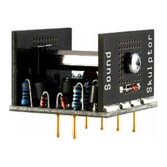
SK25 Assembly guide
Safety warning
The kits are main powered and use potentially lethal voltages. Under no circumstance should someone undertake the
realisation of a kit unless he has full knowledge about safely handling main powered devices.
Please read the "DIY guide" before beginning.
Print or open the following documents :
• SK25 Schematics
• SK25 Components layout
• SK25 Parts list
Follow this guide from item number 1 till the end, in this order. The assembly order is based on components height, from
low to high profile, in order to ease the soldering process : The component you are soldering is always taller than the
previously assembled ones and it is pressing nicely against the work area foam.
SK25 Assembly guide
1.
Soldering
All the PCB holes are metallized. It means the connection between the top and bottom pads is already
done. The parts must be soldered only from the bottom side (unless differently stated).
Use only small diameter solder, 0.5 or 0.7 mm, 1mm maximum. Use the minimum possible amount of
solder. Bad joints are almost always caused by too much solder.
Here are two excellent introduction to soldering videos:
http://www.eevblog.com/2011/06/19/eevblog-180-soldering-tutorial-part-1-tools/
http://www.eevblog.com/2011/07/02/eevblog-183-soldering-tutorial-part-2/
2.
PCB split
Split the PCB into 3 parts along the lines shown by the red arrows.
3.
Pins
Insert and solder the 6 golden pins. The pins are inserted from below the
PCB.
The best solution to keep the pins perfectly perpendicular is to use the final
host PCB (like the MP512, MP599) as a guide: Insert the 6 pins into the
1mm sockets of the receiving PCB, position the DOA PCB over the pins and
solder.
It is a good idea to protect the golden pins with some wire insulating sleeve
before doing other component soldering.
Copyright ©2014 to Today SoundSkulptor
Document revision 1.1 – Last modification : 10/08/17
www.soundskulptor.com
Advertisement
Table of Contents

Related Manuals for Sound Skulptor SK25


Summary of Contents for Sound Skulptor SK25
- Page 1 Print or open the following documents : • SK25 Schematics • SK25 Components layout • SK25 Parts list Follow this guide from item number 1 till the end, in this order. The assembly order is based on components height, from low to high profile, in order to ease the soldering process : The component you are soldering is always taller than the previously assembled ones and it is pressing nicely against the work area foam.
- Page 2 Document revision 1.1 – Last modification : 10/08/17 SK25 Assembly guide Diodes D5 & D6 Add D5 and D6 on the 2 heatsink PCB's. When soldering, be careful not putting any solder on the power transistor plane. Warning: Make sure to respect the direction of the diodes which is marked by a ring on the component and a double line on the PCB marking.
- Page 3 10. Capacitors Add C1 and C2. 11. Q9 & Q10 assembly Attach Q9 (BD139) to the heatsink PCB marked “Sound Skulptor” with a M3x12 mm screw and a M3x20 mm spacer. The transistor is placed on the side with no writing.
- Page 4 SK25 Assembly guide 12. Q9 & Q10 assembly Similarly, attach Q10 (BD140) to the heatsink PCB marked “SK25” with a M3x12 mm screw and screw it into the other side of the spacer. The transistor is placed on the side with no writing.
Need help?
Do you have a question about the SK25 and is the answer not in the manual?
Questions and answers