Advertisement
Quick Links
MP573 Assembly guide
Safety warning
The kits are main powered and use potentially lethal voltages. Under no circumstance should someone undertake the
realisation of a kit unless he has full knowledge about safely handling main powered devices.
Please read the "DIY guide" before beginning.
Print or open the following documents :
• MP573 Schematics
• MP573 Components layout
• MP573 Parts list
• MP573 Setup guide
Follow this guide from item number 1 till the end, in this order. The assembly order is based on components height, from
low to high profile, in order to ease the soldering process : The component you are soldering is always taller than the
previously assembled ones and it is pressing nicely against the work area foam.
Soldering
All the PCB holes are metallized. It means the connections between the top and bottom pads are already
made. The parts must be soldered only from below (unless differently stated).
Use only small diameter solder, 0.5 or 0.7 mm, 1mm maximum. Use the minimum possible amount of
solder. Bad joints are almost always caused by too much solder.
Here are two excellent introduction to soldering videos:
http://www.eevblog.com/2011/06/19/eevblog-180-soldering-tutorial-part-1-tools/
http://www.eevblog.com/2011/07/02/eevblog-183-soldering-tutorial-part-2/
MP573 Assembly guide – PCB split
1.
PCB split
Split the multiple PCB along the
red lines on the picture.
This will separate the main PCB,
DI PCB, input & output
transformer PCB, link PCB's and
the protection cover.
Clean up the break line with very
thin sand paper.
There are two additional safety PCB's available: One input transformer PCB and one output transformer
connector PCB. These won't be used for this build.
Copyright ©2015 SoundSkulptor
Document revision 2.3 – Last modification : 27/05/21
www.soundskulptor.com
Advertisement

Related Manuals for Sound Skulptor MP573


Summary of Contents for Sound Skulptor MP573
- Page 1 Bad joints are almost always caused by too much solder. Here are two excellent introduction to soldering videos: http://www.eevblog.com/2011/06/19/eevblog-180-soldering-tutorial-part-1-tools/ http://www.eevblog.com/2011/07/02/eevblog-183-soldering-tutorial-part-2/ MP573 Assembly guide – PCB split PCB split Split the multiple PCB along the red lines on the picture.
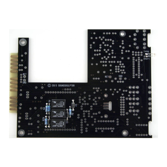
- Page 2 MP573 Assembly guide – Main PCB, B side B side The MP573 main PCB carries components on both sides. The A side is the side with the title writing “MP573”. We will start by the B side which holds only a few components.
-
Page 3: Integrated Circuit
Document revision 2.3 – Last modification : 27/05/21 MP573 Assembly guide – Main PCB, B side MP573 Assembly guide – Main PCB, A side A side Turn the board over, A side up. Make sure all the B side component leads have been cut as short as possible. - Page 4 Document revision 2.3 – Last modification : 27/05/21 MP573 Assembly guide – Main PCB, A side 12. Jumper header Solder jumper header JMP3. Solder one pin first, check verticality, then solder the other pins. JMP1 and JMP2 are for future use. They allow moving the insert point, situated between first and second stage, to the back connector.
- Page 5 Document revision 2.3 – Last modification : 27/05/21 MP573 Assembly guide – Main PCB, A side 19. DI Connector Solder the connector socket CN3a. Solder one pin first, check verticality, then solder the other pins. 20. Output TX connector Solder the connector socket CN2.
- Page 6 Document revision 2.3 – Last modification : 27/05/21 MP573 Assembly guide – Main PCB, A side 23. Small electrolytic capacitors Add C18, C27, C6, C8, C19, C29, C1. Solder one lead first, adjust verticality then solder the second lead.
- Page 7 Document revision 2.3 – Last modification : 27/05/21 MP573 Assembly guide – Main PCB, A side 30. Input transformer front PCB Use the input transformer front PCB, the one with the pin holes and numbers. Two units of this PCB are available. Only one will be used.
- Page 8 Document revision 2.3 – Last modification : 27/05/21 MP573 Assembly guide – Main PCB, A side 31. Input transformer back PCB Use the input transformer back PCB. Insert the 90°, 13 pins headers, long tails first, into the holes, from the side marked NOT VISIBLE.
- Page 9 Document revision 2.3 – Last modification : 27/05/21 MP573 Assembly guide – Main PCB, A side 36. Output transformer assembly Insert 4 M3x35mm countersunk screws into the side plate. On each screw, insert one 4mm spacer. Insert the transformer on the 4 screws and attach with 4 self locking nuts.
- Page 10 Document revision 2.3 – Last modification : 27/05/21 MP573 Assembly guide – Main PCB, A side 39. Knobs Attach the 2 knobs, using the included 1.5mm hex key. MP573 Assembly guide – DI board 40. Horizontal resistors Add R59 to R61, R63 to R69.
-
Page 11: Electrolytic Capacitors
Document revision 2.3 – Last modification : 27/05/21 MP573 Assembly guide – DI board 42. Diodes Add D11 and D12. These diodes are placed vertically. Bend the cathode leg (identified by the black ring). Warning : Make sure to respect the direction of the diodes which is marked by a ring on the component and a 'K' on the PCB marking. - Page 12 Document revision 2.3 – Last modification : 27/05/21 MP573 Assembly guide – Final assembly 49. Setup Your MP573 is now ready for test and setup. Please follow instructions in the “MP573 Setup” document. 50. DI board installation Place one 1.2mm black plastic spacer on the jack socket and insert into the front panel while fitting the CN3 connector pins into the socket on the main PCB.
Need help?
Do you have a question about the MP573 and is the answer not in the manual?
Questions and answers